Tire fitting is an excellent business choice for people who love and understand not only cars, but also how to make money. When opening your own workshop, there are undoubtedly many things you need to think about. And, perhaps, one of the first topics on the list of such issues is balancing machines. The correct choice of machine will directly determine the convenience of work for employees and the quality of the result obtained for the client. That’s why it won’t hurt to understand the best balancing machines for 2021, learn about their prices, advantages and disadvantages.
What is balancing
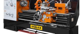
balancing machine
A wheel is considered unbalanced if its geometric center and center of mass do not coincide. When such a disk rotates, powerful centrifugal forces appear, causing the car to vibrate. In addition, suspension parts and tires wear out faster.
Balancing driveshafts and wheels allows you to avoid uneven wear of tires and increase the life of bearings and suspension. The greatest demand for balancing driveshafts and disks occurs in the off-season, when car enthusiasts switch from winter tires to summer tires and vice versa.
A wheel or driveshaft can only be balanced using special equipment. It’s not enough just to assemble the wheel correctly, it needs to be balanced. Specialized balancing machines work with disks of different sizes and shapes and provide different operating modes.
Why balancing is needed
Uneven tire wear or damage to the disc leads to imbalance, that is, an imbalance in the distribution of wheel mass relative to the horizontal and vertical planes. There are two types of imbalance:
- Static, when the axis of rotation shifts relative to the axis of inertia and begins to move the center of gravity up and down.
- Dynamic, when the axis of rotation intersects with the axis of inertia, disrupting the horizontal distribution of the wheel mass. The disk makes a figure eight while the car is moving.
There are two types of imbalance: static and dynamic
Imbalance causes the wheels to vibrate while driving. Wheel imbalance, especially when driving at high speed, worsens handling, increases the braking distance, and leads to premature wear of chassis parts.
Unbalanced wheels cause loss of control when driving at high speed. But even if an accident does not happen, constant vibration causes the hub bearing to become unusable, and over time, the entire chassis system of the vehicle breaks down.
The purpose of the procedure is to restore balance to the wheels during rotation. The result of balancing is a uniform distribution of wheel mass relative to the axes of rotation.
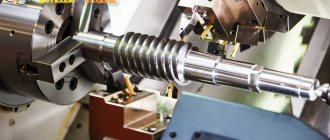
Machine device
The structure consists of supports on which the wheel is mounted, an electric motor and measurement sensors. During tire mounting, the part rotates, sensors detect pressure or vibration. Based on the data obtained, the location of imbalance is identified.
Machines differ in the design of supports, which can be:
- soft: during testing, the amplitude and frequency of movement of the support, provoked by the torsion of an unbalanced wheel, are measured. Each type of part has its own machine, so the inspection results are more accurate;
- hard: pressure and rotor phase are measured. One machine tests different types of parts - a universal fixture that gives less accurate results.
Balancing stands can have a horizontal or vertical axis of rotation. Accurate measurements are possible with an automated drive.
The speed sensor is one of the most important devices in the machine. It works on the principle of accelerometer or magnetic induction.
The rotation angle measurement sensor is the second important tester in the machine.
Based on sensor readings and the number of wheel turns, they calculate where and how much mass needs to be added.
According to the principle of data entry, balancing machines are:
- automatic;
- manual.
In the second case, the master measures the wheel manually using a ruler and enters the data manually. Automatic machines require data on diameter, disc distance and sometimes width to operate. Such equipment quickly balances cardan shafts and disks. Information is displayed on an LED or LCD monitor; depending on the model, it can be displayed in graphical or digital form.
Flexible supports are used in over-resonance machines, and rigid supports are used in pre-resonance machines.
The compliant supports undergo oscillations under the influence of an unbalanced rotating rotor.
The amplitudes and phases of the oscillations of the supports are information about imbalance. To measure vibration in this case, vibration sensors are used - accelerometers (acceleration sensors) or vibration velocity sensors. Rigid supports prevent the rotor from oscillating and, as a result, experience pressure. In this case, to obtain information about imbalance, force sensors are used and the rotor pressure on the supports and its phase are measured.
So, the supports of the balancing machine are equipped with sensors that convert their vibrations (vibration) or pressure from centrifugal forces into electrical signals. Electrical signals from the sensors enter the measuring device. The structure of the measuring device and the form of information about imbalance depend on the purpose of the balancing machine. Modern balancing machines use microprocessor-based measuring and computing devices that allow measurements to be taken simultaneously on all supports, automatically entering measurement data into the computer, which, according to a given program, calculates the positions (angle) and mass of corrective weights.
Fig.6
To rotate the rotor in balancing machines, a drive from a double-jointed shaft, from a cap belt, an air jet, etc. is used. Correction of imbalance, i.e., installation of weights or removal of material (drilling, milling, etc.), is performed manually or using drilling or milling portal mounted on the machine.
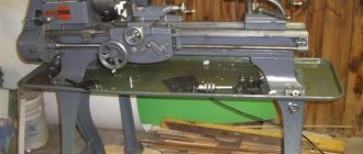
Fig.7 Machine for balancing rotors weighing up to 100 kg and distance between journals up to 950 mm TB-100. The drilling portal makes it possible to adjust the masses without removing the shaft from the machine stands.
Mechanical systems of balancing machines are classified according to the number of degrees of freedom of the rotor, as well as the number of degrees of freedom of the rotor axis together with the moving part of the machine. In the classification according to the number of degrees of freedom of the rotor, mechanical systems are distributed into seven classes (Fig. 1, a). The class number (Roman numeral) corresponds to the number of degrees of freedom of the rigid rotor. In addition, an additional sign has been introduced for dividing mechanical systems into two groups: the letter A denotes machines that have a frame on which the rotor supports are located, and the letter B denotes machines with separate supports installed on a fixed base. This division characterizes not only the design features of the system, but also the features of the balancing process, since in group A machines the choice of points for measuring vibrations is less limited than in group B. One of the signs of the technological classification of balancing machines is the degree of their versatility, i.e. the variety of rotors for which they can be used. The greater this variety, the wider the technological capabilities of the machine. Balancing machines are divided into four types: universal, specific purpose, special and balancing kits. Universal balancing machines are used in mass production to determine imbalances of rotors of various designs. This type includes over-resonance and pre-resonance machines with an axial or belt drive, which have high accuracy and quick changeover to a new type of rotor. They can be used to balance rotors that differ in mass, length and diameter by 10..40 times. Universal balancing machines are characterized by the permissible weight and diameter of the rotor, the distance between the machine supports, the rotor speed range, the drive power and the accuracy of the machine. The minimum permissible rotor mass is the mass of the rotor being balanced, at which the specified accuracy of the machine is ensured. The maximum permissible weight is limited by the strength of the support suspension. It includes the mass of the rotor, its bearings and housing, equipment, i.e. the entire mass installed on the machine supports. The permissible rotor diameter depends on the distance from the centers of the supports to the bed (floor) of the machine. The maximum distance between the machine supports is limited by the length of the bed guides, and the minimum by the thickness of the racks. For machines whose supports have a seat for installing a bearing, indicate its diameter or the largest diameter of the rotor journals. The range of rotor rotation speeds during balancing corresponds to the frequency range of the measuring device, the rotation speed and power of the drive device. Universal balancing machines are manufactured with normal and increased accuracy. To balance rotors weighing from several grams to tens of kilograms, over-resonance machines with a belt drive connection are used. Balancing of rotors weighing up to 1000 kg is carried out on over-resonance and pre-resonance machines with both axial and belt drives with a variety of measuring devices. Universal balancing machines for rotors weighing more than 1000 kg are made with an axial drive. Machine supports for heavy rotors are made pre-resonant.
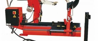
Fig. 8 Pre-resonance type balancing machine TB-6000 for industrial balancing of heavy rotors weighing up to 6000 kg, diameter up to 2000 mm and maximum distance between journals 4600 mm.
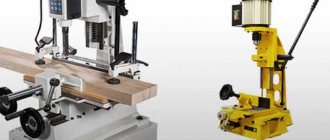
Vertical balancing machines are designed for static balancing in dynamic mode of parts that do not have their own bearing surfaces. The operating principle and design of the main components of the machine are similar to horizontal machines. A distinctive feature of vertical machines is the presence of a spindle with a vertical axis of rotation, at the end of which there is a clamping device. These machines are characterized by the permissible weight and diameter of the part being balanced, the range of rotational speeds, the drive power and the accuracy of the machine. A double-spindle drilling head moves along the vertical guides of the machine, with the help of which the mass of the part is adjusted by drilling out the required amount of metal. The machine can operate in semi-automatic mode.
Fig.9 Vertical machine TB Vert 100 for balancing disc-shaped rotors weighing up to 100 kg and diameter up to 650 mm.
Machines for high-frequency balancing of flexible rotors have pre-resonant supports, an axial drive with a wide range of rotation speeds, and a measuring device with eddy current sensors. At high frequencies, rotors weighing up to 300 tons are balanced. Therefore, in order to reduce power losses due to friction with air, the balancing device with the rotor is placed in a sealed chamber, in which a vacuum of up to 100 Pa is created using a vacuum pump. Machines for high-frequency balancing are complex devices with additional systems that provide transportation of the rotor, lubrication of its supports, vacuum in the chamber, etc.
Special balancing machines are used in large-scale and mass production to balance rotors of a certain mass and geometry. The special machine is made in several copies. To increase balancing productivity, special machines are equipped with mechanization and automation equipment. The degree of automation of the machine depends on production conditions and can be different. In the simplest case, it only includes the determination of imbalances; in a more complex case, it includes the installation of corrective masses and transportation of the rotors.
Fig. 10 Machine (stand) for balancing crusher accelerators.
The stand is designed for preliminary balancing of accelerators
of 1
crushers with masses from 50 to 1000 kg or more and diameters from 500 to 2000 mm.
The stand includes a vertical spindle 2
mounted in bearings in a frame
3
.
1
installed on it is driven into rotation by an electric motor
4
connected to the spindle using a coupling (not shown in the diagram). The electric motor is connected to the network using a frequency regulator, which allows you to change the spindle speed over a wide range.
The design of the frame provides the possibility of implementing two options for its installation on the foundation, including: - rigid fastening using foundation bolts; — installation using spring shock absorbers 5
.
Rigid mounting is usually used in the case of balancing heavy, large-sized accelerators that have a significant initial imbalance. Spring shock absorbers are used when balancing relatively small and light accelerators in order to increase the sensitivity of the stand to fluctuations from unbalance forces, which results in improved balancing quality. The measuring system of the stand includes two vibration sensors 6
and
7
, a phase angle sensor
8
and a measuring and computing unit
9.
It is used to measure the vibration of the stand frame at the spindle speed, based on the results of which the parameters of the corrective weights (their mass and removal angle), ensuring the necessary quality of balancing of crusher accelerators. This stand mainly performs rough (preliminary) balancing of accelerators. The final (finish) balancing of the accelerators is performed after they are installed in the crushers, which ensures the ability to achieve a minimum vibration level of the crushers during operation. To measure vibration and calculate the mass and installation angle of the corrective masses, the Balcom2S system is used. Also, with the help of this system, the engine of the device is started and stopped and its rotation speed is controlled. If necessary, the stand can be equipped with a system for measuring the angular position of the balanced rotor and turning it to a given angle to automate the process of installing/removing correction masses.
Fig. 11 Specialized machine TB Vent 100 for balancing large diameter fan impellers, weighing up to 100 kg.
Machine for balancing large diameter rotors, weighing up to 100 kg. It was developed specifically for balancing large fan impellers. The frame made of polymer concrete on vibration supports can be moved using a conventional rocker, which significantly expands the capabilities of the machine and makes it possible to work with impellers with a diameter significantly larger than the dimensions of the machine itself. The balanced rotor is located cantilevered on the technological shaft. The process shaft can be attached to the machine stands (in housing bearings) permanently for light-weight rotors (manual installation) or placed together with the rotor for heavier rotors (installation using lifting devices).
Balancing methods
There are three ways to balance wheels and other rotating parts:
- adjustment screws - holes are drilled into the part into which screws are tightened if necessary. They can be changed and rearranged many times, which is very convenient;
- drilling - grooves and holes are made in the necessary places to reduce weight - this is the simplest and most common method at tire shops;
- balancing rings - used only in metalworking for the repair of milling machines.
Types of devices
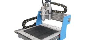
Today there are three main types of balancing machines.
- Machines for working with passenger car wheels.
- Machines for working with truck wheels.
- Universal machines. Can be used to evaluate wheels of both cars and trucks.
The main difference between these types of devices lies in the two main characteristics of the balancing machine - load capacity and diameter. It is also worth noting that the load capacity directly depends on the tire diameter.
The classification of units is also carried out according to the control method. In this case we are talking about automatic or manual devices. In the case of automatic machines, it will read all the data about the wheel independently. Setting up a manual balancing machine means that all initial data must be loaded manually by the operator. Naturally, the difference in service time on an automatic and manual machine is very different and the automatic machine works much faster. This is due to the fact that the system itself will read the geometry and other parameters of the tire. As for the technologies used by the machine to measure parameters, a variety of methods are used, including laser technologies.
Repair of balancing machines
With intensive use, mechanical or electronic faults are detected:
- the most common mechanical breakdowns are caused by falls or impacts: failure of cardan shafts, bearings, and other parts;
- electronic failures are associated with failure of power, control or sensor boards.
Signs that the machine needs repair:
- balancing does not happen the first time;
- the weight of the disk is determined incorrectly;
- The disk shape is not determined correctly.
Sometimes problems are solved by calibrating the machine. Testing of operation is carried out using a reference wheel. The balancing machine is repaired at a tire shop or taken to a workshop.
General operating principle
How does a balancing machine work? In general, the principle of its operation is as follows:
- To start working, you need to install the wheel on a special working shaft of the machine.
- Using special cones, you need to center the wheel and install it more accurately.
- Then, either manually or automatically, the wheel accelerates to the required speed.
- The balancing machine has a special measuring device that reads the parameters of the movement of the wheel on the shaft. After that, it transfers them to the device processor for processing.
- The process processes the data, generates a report about the malfunction or serviceability of the wheel, after which the report is transmitted to the display.
Homemade balancing machine
drawing of the machine: 1 - lower stand; 2 — support table; 3 - bearings; 4 — bearing housing; 5 — indicator stand; 6 — indicators; 7 - nut; 8 - shaft; 9 - cone; 10 — disk; 11 — thrust washer; 12 — tire; 13 — height adjustment bolts
- We grind the shaft, prepare places for bearings at one end, and cut a thread for a cone with a stop washer at the other.
- It is better to use bearings that have been used and have been thoroughly washed. They provide minimal resistance.
- The stand for the machine is welded with your own hands from a 52 mm metal pipe. Runout indicators are attached to the top and sides.
- To make it easier to install the wheel, a support platform is mounted.
Machine operation:
- We fix the disk in the machine with our own hands, using a nut and a cone;
- We unwind and compare the readings with the standards (horizontal should be no more than 2 g, radial no more than 1.5 g);
- We remove all the weights and check the wheel again, it stops at the heaviest point downwards, it needs to be marked;
- We turn the marked point 90 degrees and hang a weight on the opposite edge;
- If, when turned 45 degrees, the wheel stands still and does not rotate, the self-balancing was done correctly.
Interesting information about wheel balancing and balancing machine repair in videos:
Calibration
Over time, the unit used begins to give inaccurate readings. You can check its operation as follows:
- Take a wheel, for example, 16th radius.
- Install it on the machine and enter the required parameters manually.
- Activate the start button.
- After processing, the result is 25-30. We fill the weights and put the unit back into operation. The result may be 05-10.
- If after the third launch the program asks to add another load parameter, you need to check the cones for any play and their fit on the shaft.
Read also: Connecting a light switch with one legrand key
If these problems exist, mandatory calibration of balancing machines will be required. This can be done as follows:
- After bringing the program parameters to 00-00, fill a hundred-gram weight and start the machine. During normal operation, the parameters should become 00-100.
- You should think about calibration if there are differences of 5 units (for example, 05-95). You can still work on such a unit, but you will need to check the play and fastening.
- If the final value after starting the shaft with the control weight exceeds 15 units, urgent calibration of the device is necessary.
- If the steps taken to set the parameters do not lead to parameters 00-100, you will need to carry out maintenance of the equipment, clean it of contamination, and measure the mains voltage. Then recalibration is carried out.
An indispensable attribute for the service industry
Previously, such nuances were resolved using a static method. It is understood that the wheel was put on a special rod, after which it was untwisted. Stopping points were marked. To determine the area of imbalance, such manipulations were repeated several times. It could take all day to service one vehicle. In addition, it should be noted the high level of error, which was overcome years later. How often do you need to use such services?
According to ordinary people, if a car regularly drives on city roads, then it is necessary to contact a car service center at least once every six months. Such trips coincide with the seasonal replacement of tires, which allows you to save money. However, if the vehicle often drives off-road or in the suburbs, it is recommended to visit the machine once every few months. Balancing has a beneficial effect not only on the operation of the “wheels”, but also:
- Crankshaft.
- Cardan shaft.
- Compressors.
- Pulleys.
- coupling
- Rotorov.
The point is that debugging can be aimed at the functioning of individual elements of the machine. How to understand that such manipulations are necessary? For those who have only recently driven, this question is more than relevant. In order to avoid making common mistakes, you need to pay attention to how the car drives at speed and whether there is vibration in the steering wheel area. These bells are the first thing a motorist should pay attention to and visit a tire shop in the near future.
Experts advise balancing after each wheel falls into a large hole. If the impact is really strong and there is visible deformation of the disc, then you simply cannot do without stands. In addition to leveling the damaged surface, you should seek the services of specialists.
Timely contact with specialists will help to avoid many problems, including:
- Deterioration of the suspension condition.
- Accelerated wear of the wheel bearings.
- Tire tread wear.
- Increased loads on the steering.
The main task of a tire service worker is to identify imbalances and eliminate them. In this case, compensating loads on certain areas of the disk are eliminated. In addition to the employee’s personal experience, an important criterion is the availability of high-quality equipment from the world’s best manufacturers. The average cost of work will depend on the diameter of the wheel. An amount of 200 rubles does not seem that big, especially when it comes to the safety of yourself and others. What are the settings?