Electrical part
A microwave oven emits magnetic waves of millimeter and centimeter lengths. They warm up the objects they pass through well, but are completely unsuitable for welding, since it is impossible to create an electric arc on the electrode. Replacing the winding allows you to supply a large direct current to the spotter electrode . It is enough to install equipment with household power in the straightening garage.
The operating principle of a microwave spotter is based on resistance spot welding technology. The transformer produces a large current with a voltage of 12V. The impulse lasts for a short period of time. The spotter electrode should only stick to the body steel without burning through the thin sheet. This is a rare case when sticking of the electrode does not interfere with the welding process, but is specially created.
The current is changed by creating windings. The step-by-step plan for the main alterations is simple.
- Disassemble the microwave oven. Remove the microwave unit with coils from it.
- Remove the windings. The easiest way is to cut off the wires on both sides of the case and remove the bundles inside.
- Wind the primary winding with wire 2.5 mm2 in cross section, 200 - 210 turns.
- The secondary winding of the spotter is only 7 turns, the wire has a cross-section of 55 mm2. You can use a single-core cable of this diameter.
The second circuit of the spotter should produce a voltage of 12 V. The output current to the electrode is 5000 - 7000 A. The pulse duration is up to 0.5 seconds.
Head of the site for the production of welding equipment KZESO Podgorbunsky D.S.: “The wire is wound smoothly, with the turns adjacent to each other. To secure the winding in working condition and extend its service life, the finished spotter coil is impregnated with varnish. The best option is Varnish FL-98. It is manufactured by domestic manufacturers in accordance with GOST 12294-66. Produced in containers for industrial enterprises of 50 and 70 kg. For consumers, 5 liters in a canister. It can be replaced with varnishes of the ML, GF and PF series. The varnish is heated in a container to 120⁰C, and a clean, grease-free winding is carefully lowered into it. Cardboard, used as insulators between the coils and the walls of the case, is impregnated with the same varnish and dried. Impregnation with varnish significantly increases the service life of the spotter.”
Parts selection
The diagram consists of several parts. The reliability and operation of the device depends on their choice.
Transformers
These devices are taken ready-made or old ones taken from used microwaves and other equipment are rewound:
- Provides operation of the circuit and charge of the capacitor. Powers the electrical circuit with 12V voltage. Its power doesn't matter.
- The capacitor is discharged through its primary winding, and the secondary winding creates a pulse of welding current. Provides operation of the welding tool. The secondary winding contains 2-3 turns of cable or thick busbar.
The selection of a microwave transformer for a spotter is made based on power - the higher it is, the more powerful the device is.
Thyristors and diodes
The type of thyristor can be any. The only requirement is a current of at least 50A and a voltage of at least 300V. The parameters of the diodes powering the working tool and the operating mode are similar. Since the device operates in pulse mode, diodes and thyristors are not installed on radiators.
Together these elements make up a thyristor switch. Instead of a thyristor and powerful diodes, it is allowed to use a triac with the same operating parameters.
The diode bridge feeding the capacitor is made from any low-power diodes, for example, 226B.
Information! Although the network is considered 220V, this is the effective value of the sinusoidal voltage. The parameters of diodes and thyristors are calculated based on the maximum value of the sinusoid, which is greater by √3 and amounts to 308V.
Capacitors and resistors
Variable resistance controls the amount of welding current. The strength and duration of the welding pulse is adjusted by controlling the opening angle of the thyristor. A variable resistor is used for this. Its value is 100 Ohm. Since it is located in the thyristor control circuit, the current flowing through it is minimal and amounts to a few milliamps. Therefore, the power of the resistor does not matter.
Electrolytic capacitor, with a capacity of at least 1000 μF, with an operating voltage of more than 25V.
Ensuring convenience and safety of work
A homemade spotter, created with your own hands from a microwave oven, requires a body and handles for turning on and adjusting. If desired, you can make it from sheet metal. Experts recommend cleaning the microwave from the remaining parts and placing the assembled spotter structure in it . The holes on the front panel are used for the regulator. The wires exit from the rear. The nodes are attached to the walls.
The wiring diagram is used from the furnace. Microwave plug with grounding. The wire will withstand short loads, but it is short and will not allow you to move around the car with the spotter. It is replaced with a long wire. The cable from the secondary winding is brought out, reliably insulated and brought to the holder.
Home workshops have a small area, but the created spotter must be moved during the work process. To do this, handles are attached to the top of the device, and wheels from a broken chair are attached to the bottom.
Before checking the operation of the equipment, it should be carefully inspected and all connections should be insulated . Cardboard is placed between the units and the walls of the housing.
A simple electrical circuit for a homemade spotter.
Using Dual Row Transducers
You can make a spotter with your own hands with a two-row converter only if you first find a generator for it. As a rule, a single-phase model is selected, in which the output voltage parameter is at the level of 4 V. Due to this, fairly good conductivity will be ensured. Next, you need to solve the problem with the transformer. In this situation, it is best to set the analog type.
Due to this, the nominal voltage in the system can be reduced to 5 V. To make a spotter with your own hands, it is recommended to select capacitors with a capacitance of 12 pF. They will provide good current conductivity. There should be three resistors on the board. In this case, only stricture filters are used. They are able to stabilize the operating frequency parameter at 45 Hz. Some specialists additionally install two-wire modulators at transformers. All this is necessary to ensure that welding is not interrupted during sudden voltage surges. The last thing you should do when assembling the spotter is installing the power supply.
Manufacturing method
Before starting to make a spotter, you need to make a drawing and prepare all the details. In addition to the transformer you converted yourself, you will need:
- diode bridges D32A and D226B;
- thyristor PTL50;
- 1000uF capacitor;
- 100 Ohm resistor;
- fuse;
- power button.
All components and parts must be conveniently placed in the housing and isolated from each other.
Homemade products begin to be made from transformer windings . After this, the remaining parts are connected to the circuit one by one.
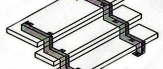
Frame
It is optimally convenient to use the body of a disassembled microwave oven. After removing the disk and rotation mechanism, you should strengthen the bottom with plywood or a sheet of dielectric.
At the back, where the wires exit, bolts are inserted into the holes and tightened with nuts. The plus and minus wires are attached to them. The mount is fixed on the inside. From the outside, the cable terminals must be freely removable and secured with nuts.
The holes in the microwave body are used to control the current and voltage of the spotter.
Holes are drilled in the upper part of the case, and a handle is installed for convenient movement of the device. If the spotter turns out to be very heavy, wheels are attached to it or mounted on a crosspiece from a computer chair.
Spotter control circuit.
Holder, electrodes
Mechanics who straighten car bodies with a spotter recommend making a holder from an old glue gun . The cable is routed from the back. At the front, the spout is removed and a sleeve is installed, firmly connected to the body and a long tube. The button is replaced by a switch.
In the absence of suitable broken equipment, the body of the handle is cut out of plywood. The inner surface is covered with insulation. A hole is made on the handle for the starter so that the button can be pressed without removing your hand.
An electrode in the form of a plate with a sharp end is made of copper . It is short in length and is attached to the rod with a nut and bolt with washers.
You can make an electrode from a copper tube. It is connected to the cable with a union nut or soldered. The working end is flattened. The point of contact with the metal of the housing should be minimal.
Inoppuller
A reverse hammer, with the help of which the dent is gradually leveled - inoppuller . It is a long hollow rod with a handle. A device for holding the electrode is attached to its end. The other end of the inoppuller is attached to a pistol holder. There is a wire running inside that supplies current.
It is necessary to ensure a good connection between the cable and the electrode and reduce current losses to a minimum. The handle should be comfortable, well insulated from all conductive parts.
How does a spotter work?
The operating principle of this device resembles a spot welding machine. This type of welding is called “resistance welding”:
- The “mass” of the spotter is secured with a clamp to the body;
- the working tool to which the electrode is connected is pressed in the required place;
- the welding current is switched on briefly;
- the welding site is heated to a temperature 10% less than the melting point;
- After cooling, the working tool “sticks” to the body.
Washers, hooks, reverse hammers and other elements are used as working tools. After the work is completed, these parts are broken off from the base.
Important! The contact area must be cleaned with sandpaper.
To reduce the length of cables and losses in them, the electrical circuit of the device is located in the housing, next to the welding site. It can be assembled from two old transformers, including those taken from failed microwave ovens, and several additional parts.
The electrical circuit of this device works as follows:
- the mains voltage is supplied to the first step-down transformer;
- the reduced voltage is supplied to the diode bridge, where it is converted from alternating to direct;
- through the switch, the rectified voltage charges the capacitor;
- when the welding mode is turned on, the relay disconnects the capacitor from the diode bridge and turns on the thyristor in the control circuit;
- the opened thyristor connects a second transformer to the network, which has a low-voltage winding of 2-3 turns from a cable with a cross-section of 50 mm²;
- after the capacitor is discharged, the thyristor closes and welding stops.
- After the container is discharged and the “Impulse” button is turned off, the cycle is repeated.
Important! The duration and magnitude of the welding current pulse depends on the capacitance of the capacitor and the parameters of the resistor.
Application
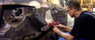
During the straightening process, the electrode is welded pointwise to the dent and, with the help of an inoppuller used as a return striker, is pulled out. In this case, the tack breaks, the electrode is displaced and the straightening process is repeated again. Gradually, point by point, the dent is leveled out.
The spotter is used for straightening metal bodies . The dent should be cleaned from paint to bare metal. The clamp of the second pole is attached to the area of the body being leveled next to the area being treated. The main condition is the occurrence of a short arc between the part and the electrode.
Schematic diagram
The only thing that will make you scratch your head is the circuit diagram that you need to understand. This is a diagram of the simplest of the different types of spotters.
The main unit of the spotter will be a welding transformer, and the voltage transmitted to its winding is supplied through a diode bridge, which contains a transistor. This resistance is controlled by changing the voltage transmitted by a low-power transformer.
Features of a homemade device
A homemade device is less productive than professional equipment from car dealerships. For repairing your car, it has the following advantages:
- cheapness;
- DIY repair ability;
- small size.
In terms of power - welding force, a homemade spotter is inferior to a ready-made spotter from a store . This is a plus of the equipment. Body straightening requires skill. Low effort allows you to gradually, little by little, level out the dent, without fear of making a mistake.
Anyone who knows how to do mechanics and understands electrical circuits can make a spotter with their own hands. The equipment is necessary in every garage, although it is not constantly used.
How to make an electrode for a spotter
Spotter electrodes and adapters are small cylindrical attachments made of brass, each of which is used to work with certain types of welding fasteners: washers, nails, studs, crimped wire rivets. In stores, each of these elements can cost from 500 to 1000 rubles or more, and for ordinary body work you need at least five or six types of electrodes:
- for rings;
- for spot welding;
- for corrugated wire;
- for welding with carbon electrode;
- for triangular washers;
- for pins and nails.
Making them yourself is not so difficult, but it requires certain skills and the availability of appropriate equipment. Alternatively, you can make only the simplest attachments with your own hands, and order more complex ones in a workshop with turning and drilling equipment.
In battery spotters, batteries with a capacity of 40÷60 Ah are usually used as a power source. If anyone has had to work with such devices, please write in the comments: how quickly the battery discharges and how the quality of welding changes as it discharges.
From faulty devices you can extract a large number of different spare parts, which can be used not only to repair other devices, but also to independently manufacture original products. One of these useful homemade crafts is spot welding, which is quite easy to make from unwanted microwave ovens.
Don't throw away your old microwave
How to make a spotter yourself from an old microwave will be discussed in detail in this article.