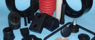
What is drawing
The operation consists of pulling a metal workpiece through a die - a hole with dimensions smaller than its own. As a result of compression, the original product becomes thinner and longer, and the cross-sectional shape may change.
The die has the appearance of a tapering channel. The tool in which the hole is made is called a die.
Purpose of the procedure
Drawing is used to manufacture the following types of products:
- wires up to 1-10 microns thick;
- rod, including shaped rod;
- profiled and round pipes - with a diameter of 0.3-500 mm and a wall thickness of 0.05-6 mm.
From the resulting shaped profile, support prisms, segment keys, spline rollers, etc. are made by cutting.
Where is it used?
The method is used in metallurgical production. The scope of application of the resulting products is the widest.
Drawing is used in metallurgical production.
For example, the following types of wire are made using drawing:
- electrical, used for welding;
- knitting;
- hardened;
- spring stainless.
These products are used to make:
- wires and cables;
- cables;
- chain-link mesh, etc.
The rod is used for various purposes, for example, as reinforcement.
Pipes - for creating metal structures and transporting liquid or gaseous products.
Types of drawing
There are several variations of the method.
The choice depends on a number of criteria:
- workpiece material;
- cross-sectional dimensions of the final product;
- required performance.
The choice of drawing type depends on the cross-sectional dimensions of the final product.
By type of procedure
The following types of drawing are distinguished:
- dry;
- wet.
The difference lies in the method of applying the lubricant. In the first case, the workpiece is immersed in soap powder before the die, in the second - in an emulsion.
This treatment gives the following positive effect:
- reduces heat generation;
- reduces energy consumption for drawing;
- Extends tool life.
According to the purity of processing
There are 2 types of operations:
- rough;
- finishing.
The result of finishing operations is a wire of the required size.
The first act as an intermediate stage. The products obtained with their help serve as blanks for finishing operations, the result of which is a wire or rod of the required size, shape and quality.
By frequency of transitions
The multiplicity is understood as the number of passes, i.e., broaches through dies of different diameters to which 1 workpiece is exposed.
The following types of procedure are distinguished:
- one-time;
- multiple.
In some cases (for example, when drawing copper wire) the number of passes reaches 18-22.
The single-shot method is mainly used for the production of thick, poorly deformable wire with a diameter of 8-20 mm.
By processing
There is an indicator of parallel processing. It indicates how many workpieces are drawn at the same time.
Most often, several workpieces are processed at once.
On this basis, the following types of procedure are distinguished:
- single thread;
- multi-thread (most often 2, 4 or 8 workpieces are processed).
By mobility
The following types of dies are used:
- motionless;
- rotating relative to the longitudinal axis of the channel.
The second type is used for the manufacture of round products.
Spin allows you to win the following:
- the coefficient of friction decreases;
- tool wear is reduced and becomes uniform.
Disadvantage - it requires a complex drive and additional energy costs to ensure a rotation speed of 50-200 rpm.
By heating
Drawing happens:
- Cold. The workpiece has a temperature of +60…+180°C. This is how high-alloy steels with austenitic and austenitic-ferritic structure are processed. Slight heating increases the plasticity of the material and improves the mechanical properties of the wire, while the austenite remains stable.
- Teplov. It involves heating to a recrystallization temperature of about +500°C. The method is used for processing high-speed steel.
- Hot. The workpiece is heated to post-recrystallization temperatures - about +900°C. The method is used for processing low-plasticity metals. It is used, for example, to draw aluminum wire, workpieces made of titanium, molybdenum, iridium, tungsten and their alloys.
Heating the workpiece increases the ductility of the wire.
The material being processed is heated using electrical contact or induction methods.
Annealing copper wire
Continuous annealing is almost always used to recrystallize the wire. After annealing, the wire passes through a low concentrated extinguishing emulsion. The entire line of Multidraw emulsions for drawing copper wire, suitable as an additive to annealing water, with a concentration of 0.5% - 1.5%.
After this emulsion, a thin layer of film remains for annealing, which protects the wire from tarnishing and promotes winding of the wire.
Copper wire drawing with annealing. Z&G Annealing Products
Multidraw CU GWZ is a special emulsion for continuous annealing of copper wire. The product guarantees excellent protection of the wire from the influence of weather conditions, as well as from corrosion for a longer period of time, even for “wet” wire. This emulsion prevents tarnishing of the wire and is suitable for regular and tinned copper wire of all diameters.
Application: Nexans (Germany), ALCABE (Spain).
Features of the drawing procedure
The technological process is considered simple. To obtain high-quality products, you only need to choose the right procedure parameters.
Preparation of blanks
Before being fed into the die, the workpiece is subjected to the following types of processing:
- Removing scale. It interferes with drawing and shortens tool life.
- Annealing. The procedure involves heating with slow cooling. Relieves internal stress in the material, makes it plastic and the structure fine-grained.
- Sharpening and straightening the end with a hammer or forging rolls. Without this, the workpiece will not be able to be inserted into a narrow die.
Necessary equipment
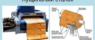
A machine for making rods and other products using this method is called a drawing mill.
Its main elements are:
- mechanism for creating traction force;
- a clip with a drawing plate installed in it (drawing board).
The rod making machine contains a mechanism for generating traction force.
Machines from UDZWG (Germany) and Samp SpA (Italy) are widely used.
The tool is made from materials with the following characteristics:
- high hardness;
- abrasion resistance;
- low viscosity.
Suitable for this:
- High-quality tool steels of grades U8 – U12. To make them wear-resistant, they are heat-treated and chrome-plated.
- Chrome-molybdenum steels (for example, grade X12M). The channel walls are hardened in a cold state; heating and chrome plating are not used.
- Other steels (for example, grades ШХ15 and 40Х5Т). Hardening is achieved by heat treatment, chrome plating, carburizing and other methods. Medium drawing machines are equipped with carbide tools.
- Solid metal-ceramic materials. They are based on thermocorundum, boron carbides, titanium, tantalum, molybdenum, and tungsten. Cobalt is introduced as a metal binder.
- Natural and technical diamonds. Such a tool is used to produce products from non-ferrous metals and their alloys. Diamonds are small in size, so the diameter of the dies made in them does not exceed 2 mm.
Steel tools are used for rough drawing, diamond tools for fine drawing.
There are dies:
- monolithic;
- compound.
Composite dies are universal.
The latter are mainly used for the production of shaped profiles.
This tool has the following advantages:
- versatility;
- increased wear resistance and easy repair by replacing the liner;
- the ability to assemble a die with a large hole from small carbide fragments;
- high speed of operation.
Wire drawing dies have a round cross-section; they are most often made in monolithic dies.
To study the processing process and set up equipment, a drawing machine emulator simulator is used.
About the essence of the operation, the process of execution
Drawing is the name for the process of drawing workpieces through holes that are tapered. In this case, the source material can be anything:
- Aluminum.
- Steel.
- Copper - it also allows the use of tools such as dies for drawing wire.
A drag is a tool that is used to solve a problem. Die is the name of the hole whose configuration determines the shape of the finished profile after processing.
Compared with rolling by a wire drawer, the drawing technique guarantees improved cleanliness and precision on the wire surface. The same applies to pipes, rods and other parts with different dimensions. After such processing, the characteristics of the material change, only for the better. This is due to the fact that the finished parts receive additional reinforcement.
The technology is especially popular in the manufacture of shaped profiles that require high strength. Successfully produced pipes with different diameters, wires with cross-sections ranging from 1-2 microns to 10 millimeters. Larger figures are also possible. The drawing prism helps to achieve an accurate result.
When using modern drawing technologies, high productivity of the equipment is guaranteed. It's also easy with portages. Even high-speed operations do not prevent you from achieving results constantly, without periodic failures. The amount of compression of the source material remains serious. You just need to use the right wire drawing machine.
The drawing process itself consists of several stages, including:
- First, the raw materials are etched in a sulfuric acid solution, the temperature of which is approximately 50 degrees. This operation is performed to extend the service life of the matrices. The effect is achieved by removing scale from workpieces.
- After the first stage, preliminary annealing of the metal surface is carried out. It is performed with the aim of increasing various characteristics of the source material. This ensures a fine-grained structure at the base. In addition, modern methods protect the wire from damage.
- The aggressive solution is neutralized so that etching can be carried out. After preparation, they are washed. Without this, pipe drawing is impossible.
- The ends of the original metal raw material are sharpened using a hammer or forging wolves.
- Direct drawing process.
- Performing annealing. This is where the pipe drawing ends.
The finished wire can be subjected to additional processing operations, including cutting products to the required lengths, straightening, removing ends, and so on. There are no fingerprints on the products.
Drawing methods and patterns
Different types of machines are used. The choice depends on the final product you want to achieve. A large enterprise has a whole fleet of mills.
For the production of products of limited length, such as calibrated rods and large diameter pipes, straight-fed machines are used. The traction force is created by a chain, rack or screw drive.
Drum
This is an option for long products – wire, etc., supplied in coils. The final product is wound onto a bobbin that creates traction. Its diameter does not exceed 750 mm.
Drum drawing winds the wire onto a bobbin.
Drum drawing is fully automated. The reels are serviced and the workpieces are placed by lifts.
Non-clogging
In this method, the workpiece is not pulled out of the die, but is pushed into it from the other side. As a result, it is possible to reduce the duration of the procedure by eliminating operations to prepare the grip.
Without rim
A mandrel is a part used to level the inner surface of a drawn pipe.
Processing without this tool is carried out in 2 stages:
- the first die centers the workpiece;
- the second one squeezes it.
Mandrelless drawing levels the surface of the pipes.
Disadvantages of arborless drawing:
- poor quality of the internal surface;
- different wall thickness.
Because of this, this method is mainly used as an intermediate method to reduce the diameter of the pipe being drawn.
For thin products, it can play the role of a finishing operation.
Non-slip Wet Wire Drawing Machine
DESCRIPTION
INVENTION
FOR THE AUTHOR'S CERTIFICATE
Union of Soviets
Socialist
Republics (61) Additional to auto. svid-vuv” (22) Declared 03/07/79 (21) 2734370/22-02 with the addition of application No. “(23) Priority” (51) M. Kl, z
AT 2! From 1/08
State government (53) UDC 62! .778, .133(088 Published 11/30/82. Bulletin No. 44 pv aela navbretenny n open
Date of publication of the description 05.12.82
V. A. Davydov, V. I. Khromov, I. M. M4keev, A. M. Kogos and L. I. Rymarenko (72) Authors of the invention
L!
A
i
)l.
C (71) Applicant (54) WET WIRE DRAWING MILL
NO SLIP
The invention relates to drawing production, namely to drawing mills and technological lubrication and cooling systems, and can be used in the design of new designs of wet drawing mills driven by hydrodynamic transmission.
There are several types of wet wire drawing mills, both with coaxially located drums (with stepped drums of different diameters and the same diameter), and. with sequentially arranged drums, operating with wire sliding on the drums and equipped with process lubrication supply systems, in which emulsions of various compositions are used as a cutting fluid.
Thus, when drawing low-carbon steel wire with liquid lubricants, as a rule, aqueous emulsions of mineral oil and soap are used. When such an emulsion remains stationary in a tank for a long time, it thickens and separates, therefore, before starting the drawing process, such an emulsion must be prepared for its implementation by
2 heat it to the optimal process temperature, which is in the range of 40 – 60 C and mix thoroughly.
Therefore, process lubrication systems are equipped with various types of heaters built into emulsion tanks: electric heaters or coils with coolants in the form of steam or hot water.
For example, the same type of drawing machines VSP-10 - 1!/450 and VSG1 - 7-! O
8/450, which contain sequentially arranged drums with a group drive from an electric motor through gears. Liquid process lubricant is supplied to the protective casing-bath on the fiber drums and into the fiber holders from a special pumping unit. Three retractable tanks equipped with electric heaters and cooling devices serve as lubricant containers. Gears and bearings are lubricated with liquid circulating lubricant from the pump unit. All drawing drums are water-cooled from the inside. In these mills, electric heaters provide heating of the process lubricant to the parameters necessary for the drawing process, and mixing is carried out by distilling it with a pumping unit in a closed circulation circle: tank - pumping unit bath - tank (I).
The disadvantages of this mill design include the presence of a special heating installation for preparing the emulsion for operation, which complicates the design of the mill, as well as the unsatisfactory quality of the emulsion in terms of such parameters as dispersion and homogeneity, since a simple partition of the emulsion flo around the circulation circle of the system does not ensure the achievement of the required indicators.
A wet wire drawing mill is also known, equipped with an emulsion process lubrication system, which consists of a pump that sucks the emulsion from the oil sump of the drawing mill and supplies it to the supply tank. From this circulation tank, the pump takes the emulsion, pumps it through the heater, then through the cooling device, and then delivers it to the mill to the die holders with dies and a pulling drum. The emulsion system is also equipped with temperature controllers, valves, filters, pressure gauges and a thermometer. Before drawing the Hd wire in the mill, the heater is turned on and the pumps are pumped through the lubrication system, which is heated to the optimal temperature (35-40 C} drawing. Once this temperature is reached, the drawing mill is put into operation, the heater is turned off and a cooling device is connected to remove heat, transferred to the lubricant as a result of deformation work (2).
The disadvantages of this mill design are the presence of a special heating installation for preparing the emulsion for. work, which complicates the design of the mill, as well as the unsatisfactory quality of the emulsion.
A wet wire drawing mill is also known. non-slip, including blocks of pulling drums installed on the frame, driven from electric motors through adjustable torque converters, containing pump wheels and drive adjustment valves located in their working cavities, draw holders with dies, placed together with the pulling drums in the bath, as well as a process lubrication supply system, containing a pumping unit, the pressure line of which is connected through adjustable chokes with fiber holders and a bath connected at its lower level with an emulsion tank (3).
The disadvantage of the mill is the need to use a special heating unit to heat the emulsion
This design of the wet wire drawing mill without sliding makes it possible to eliminate a special heating installation and carry out the heating and mixing process in one unit - in an adjustable torque converter in its operating mode with the valves closed using the power of the electric motors of the main drive of the mill.
At the same time, the process of preparing the emulsion for drawing is intensified by accelerating the heating of the emulsion to the required temperature, and the quality of the emulsion is improved with an increase in its parameters such as dispersity and homogeneity.
This solution allows for the most efficient use of the mill equipment used and expands the functionality of torque converters. At the same time, the machine time of the mill increases, the technological process of drawing is improved, and the operation and maintenance of the mill is simplified. in order to bring its temperature to the required temperature for the drawing process, which complicates the design of the mill.
In addition, a simple
The purpose of the invention is to significantly improve the quality of emulsion mixing
10 with an increase in its dispersion and homogeneity, intensification of the process of heating the emulsion to the temperature necessary for the drawing process, as well as simplifying the design of the mill due to the elimination of a special heating installation for heating the emulsion before drawing.
This goal is achieved by the fact that in a wet wire drawing mill without slipping, including installed
2p on the frame are blocks of pulling drums driven from electric motors by means of adjustable torque converters containing pump wheels and drive control valves located in their working cavities, drawer holders with fibers placed together with the pulling drums in the bath, as well as a process lubricant supply system. containing a pumping unit, a pressure line to which is connected by means of adjustable
The chokes with drawer holders and a bath connected at its lower level with a hook for the emulsion; the cavities of the torque converters at the entrance to the pump wheels are connected to each other and to the pressure line of the pumping unit, as well as to the bath at its upper level through pipelines and channels made in torque converters.
977080
The drawing shows a diagram of the mill equipment in terms of the emulsion system.
The mill contains a frame 1 on which blocks with coaxially located pulling drums 2 and 3 are mounted, driven from electric motors 4 and 5 by means of adjustable multi-turbine torque converters 6 and 7. Die holders 8 and 9 together with pulling drums 2 and 3 are placed in a casing-bath 10 , which is also mounted on the frame 1, the Mill is equipped with an emulsion system, which includes a tank 11, which can be built into the frame 1, and a centrifugal pump 12, which is connected by its pressure line 13 through adjustable throttles !4 and !5 with draw holders 8 and 9, as well as channels 16 and 17, made in torque converters 6 and 7 with their cavities 18 and 19, in which pump wheels 20 and 21 and annular drive valves 22 and 23 are built.
The cavities 18 and !9 are connected by drain pipelines 24 and 25 to the upper level of the bath 10, which in its lower level is connected by drain pipeline 26 to tank 11 25.
Wet drawing mill I wire without slipping in the pre-mode) ToBKH emulsion works as follows.
By turning on the electric motors 4 and 5, the pump wheels 20 and 21 of the torque converters 6 and 7 are rotated. After closing the cavities 18 and 19 in the torque converters 6 and 7, the dampers 22 and 23 built into them turn on the pump drive
12, which with its suction pipe takes the emulsion from the tank 11 and directs it through the line 13 and channels 16 and 17 into the cavities 18 and 19 of the torque converters 6 and 7.
At the same time, the emulsion is supplied to the fiber holders 8 and 9, through 40 chokes 14 and 15 adjusted to low flow. The emulsion is removed from the torque converters 6 and 7 through drain pipelines 24 and 25 into the bath 10, from which through the pipeline 26 connected to it in lower level, the emulsion is drained into tank 11.
The operation of the torque converter in the mode with the valves closed corresponds to the zero value of its mechanical efficiency. The torque converter does no useful mechanical work. However, in this mode it does not consume all the power that the drive motors can develop. Depending on the specific design of the torque converter, the power it consumes in the mode with the dampers closed can reach up to 50″/0 of the installed one, and this power is usefully used for intensive heating and mixing of the emulsion.
The flow rate of the emulsion in the circulation circle in the cavity 18 and 19 of each torque converter 6 and 7, carried out by the pump wheel 20 and 21 when the torque converter is operating with the damper 22 and 23 open, is many times higher than the productivity of pump 12 and both of these flow rates are practically not interrelated. With valves 22 and 23 closed, the flow rate of the emulsion in torque converters 6 and 7 sharply decreases, thickens and occurs significantly more
Fluid exchange in cavities 18 and 19 is mainly determined by the performance of pump 12.
After repeatedly passing the emulsion through the circulation circle tank - pump - torque converter - bath - tank, it is heated to the temperature required for the drawing process and completely mixed, after which the mill is filled with wire, followed by drawing it.
Thus, the proposed design of a wet wire drawing machine without sliding is multifunctional, quite simple and easy to use, and can be effectively used in drawing machines that use an adjustable hydrodynamic transmission.
Claim
A non-slip wet wire drawing mill, which includes blocks of pulling drums installed on the frame, driven from electric motors by means of adjustable torque converters, containing pump wheels and drive adjustment valves located in their working cavities, die holders with dies, placed together with the pulling drums in the bath, as well as a system supply of process lubricant containing a pumping unit, the pressure line of which is connected by means of adjustable chokes with fiber holders and a bath communicated at its lower level with an emulsion tank, characterized in that, in order to simplify the design of the mill by eliminating the special heaterH0H installation and at the same time improving quality of the emulsion and intensification of the process of its preparation for drawing, the cavities of the torque converters at the entrance to the pump wheels are connected with each other and with the pressure line of the pumping unit, as well as with the bath at its upper level through pipelines and channels made in the torque converters.
977080
Compiled by G. Rostov
Editor E. Papp Techred I. Veres Proofreader M. Sharoshi
Order 8777/1! Circulation 845 Subscribed
VNIIPI of the USSR State Committee for Inventions and Discoveries
113035, Moscow, Zh - 35, Raushskaya embankment, 4/5
Branch of PPP "Patent", Uzhgorod, st. Proyektnaya, 4
Sources of information taken into account during the examination
1. Wire drawing production
Catalog 18 – 1 – 78, sheet No. 21 and 22. M., NIIInformtyazhmash.
2. Wire World International, 1972, No. l4, III/IV, 65 – 66.
3. Copyright certificate of the USSR according to application No. 2487081/22-02, class. AT 2! Since 1/14, 1976.
Features of working with copper wire
For the production of this product, blanks obtained by casting are used. At the first stage, they are fused into a single whole and subjected to rolling.
The wire is fused into a single whole by casting.
An oxide film forms on the surface of copper, like aluminum. It is removed using an aqueous solution of sulfuric acid heated to +45...+55°C. If this is not done, the quality of the wire will be unsatisfactory.
Features of the technological process:
- the workpiece is lubricated with a soap-oil emulsion;
- use diamond dies and mills with a multiplicity of 15 to 22.
When producing copper wire with a diameter of up to 50 microns, the submersible method is used.
In this scheme, the workpiece is immersed in a lubricant; intermediate annealing is not used.
Drawing of copper blanks
When drawing copper wire from copper blanks, cast blanks are always used, and this is what the entire method is based on. First you need to fuse all the workpieces together. Immediately after this, while they are still hot, they are rolled. However, this process entails the appearance of a film of oxides on the surface of the product. To get rid of this problem, it is necessary to carry out treatment with chemical compounds. After this, you can proceed directly to the drawing procedure.
The production of copper wire can also be carried out using the principle of submersion molding. If you use this method, the surface of the wire rod will remain clean and the cleaning procedure will be avoided. This is the method used to produce the thinnest wires (up to 10 microns in diameter). However, when using this method, it is very important to choose a composition that will have suitable properties.
Among these compositions are:
- complex solutions, which can be alkaline compounds, salts of fatty sulfonated oils and several other substances;
- it is possible to use various types of emulsions, such as anionic, anti-foam, synthetic ethers and others;
- Synthetic substances, such as organic and inorganic salts, as well as polymer solutions, are considered separately.
Methods for removing scale
The workpiece is freed from scale using different methods. They are often used together.
Chemical
They use solutions of acids - nitric, hydrochloric, phosphoric, hydrofluoric, etc.
Before immersion, the workpiece is subjected to the following types of processing:
- degreasing;
- grinding;
- polishing;
- cutting out defective areas.
Acid solutions are used to remove scale.
The solution is heated to a temperature of +50°C. After processing, the workpiece is washed in water or solvent and dried for 1 hour in an oven at a temperature of +75...+100°C. Properly processed metal becomes matte.
The disadvantage of acid cleaning is that the procedure involves health risks and requires the drawer to have the ability to work with hazardous substances.
Mechanical
The workpiece is bent, twisted and stretched, and then processed with tools:
- abrasive brushes;
- needle cutters;
- micro-cutting devices.
The workpiece is treated with abrasive brushes.
Electrochemical
Acid etching is combined with the action of direct electric current.
There are 2 types of method:
- Anodic. The positive pole of the current source is connected to the workpiece. As a result, oxygen accumulates on it, which leads to the detachment of oxides. The method is used to remove thin films from the surface of alloy and carbon steel.
- Cathode. The negative pole is connected, as a result hydrogen accumulates on the workpiece. It reduces iron oxides. This is a more dangerous method: scale detachment cannot be precisely controlled, and the metal often becomes brittle.
Combined
It involves a combination of chemical and electrochemical methods. The combined method is used in the most difficult cases.
Drawing stages
Wire production technology is divided into five stages.
Stage No. 1
The etching procedure to remove the surface layer of the material - scale, which interferes with drawing:
Metal pickling in a continuous pickling unit
- Surface preparation: degreasing, grinding, polishing, cutting out defective areas.
- Scale contains complex compounds of other elements, so the feedstock is subjected to chemical or mechanical treatment.
- The choice of etching method depends on the nature of the metal. Descaling is carried out with phosphoric, hydrochloric, nitric, hydrofluoric or sulfuric acid heated to 50 0C.
- The surface to be treated is cleaned of etching products. This is washing the workpieces using a special solvent or water.
- After the procedure, the metal should acquire a matte tint.
- Dry the wire for an hour at a temperature of 75–100 0C. For this purpose, special machines with drying chambers are used.
Stage No. 2
Thermal processes include processes
Heat treatment is carried out in order to make the workpiece semi-soft, with a fine-grained structure, free from internal stresses. The metal is heated to a certain temperature, kept in such conditions for some time, and cooled.
Annealing changes the properties of the material and facilitates the wire drawing process. The heating rate depends on the thermal conductivity of the metal. The rate of cooling is determined by the hardness to be achieved after annealing. Steel wires cool more slowly than carbon compounds.
Stage No. 3
Using a special hammer or forging rolls, the ends of the workpiece are flattened and leveled. The procedure allows you to fix the metal on the machine drum and pass it through a die.
Wire drawing die
Stage No. 4
Wire drawing: The pickled processed raw material is drawn on the machine at maximum speed through a smoothly tapering channel. Depending on the number of simultaneously pulled rods, the process is:
- Single thread.
- Multi-thread.
By type of final product:
- Long products in the form of skeins or coils.
- Calibrated rods.
Depending on the number of transitions, wire drawing has two types:
- Single - in which pulling is carried out through one die. The process is suitable for thick, poorly deformable wire.
- Multiple, when the material is compressed sequentially on several dies.
The drawing machine forms the profile and dimensions of the finished product.
Stage No. 5
The final stage involves annealing. This is done to eliminate harmful stress after drawing. The product becomes soft, tear-resistant, flexible to bending, elongation and twisting. After heat treatment, additional finishing operations are carried out, including:
- Wire galvanizing.
- Preservative lubricant.
- Cutting into pieces.
- Marking.
View of the finished wire after all processing processes
Pros and cons of drawing
The advantages of the technology are:
- high productivity: in modern machines the figure reaches 60 m/s;
- possibility of full automation;
- accuracy of product geometric parameters;
- the quality of their surface;
- the possibility of obtaining a final product with a diameter of up to 1-2 microns.
Flaws:
- high drag cost;
- frequent intermediate annealing;
- the need for heat treatment of the final product;
- limited range of products.
Despite some inconveniences, the method is in demand, since products obtained with its help are widely used both in industry and in everyday life.