Kinematic diagram of a screw-cutting lathe 1k62
When analyzing the kinematic diagrams of metal-cutting machines, the main working movement
and
feed movement
.
Main labor movement
. The main movement drive – the gearbox has 6 shafts. Shaft I (Figure 21) is driven by an electric motor
(N = 10 kW, n = 1450 rpm) through a V-belt drive with pulleys with a diameter of 142 and 254 mm. This shaft houses a plate-type friction clutch M1, the switching of which reverses the rotation of the spindle. When the clutch is turned to the left, rotation from shaft I to shaft II is transmitted through gears 56 - 34 or 51 - 39, and when the clutch is turned to the right - through gears 50 - 24 and 36 - 38. In the latter case, the transmission of motion is carried out through a block of intermediate (parasitic) gears 24 - 36, which change the direction of movement of shaft II, and, consequently, the direction of rotation of the spindle.
When the clutch is turned to the left, direct rotation of the spindle is ensured - clockwise when viewed from its non-working side, when turned to the right - reverse rotation. Reversing the spindle movement is necessary for carrying out heavy cutting work (large diameters, hard materials) when the spindle rotates in reverse, as well as for removing a tool fixed in the tailstock when machining holes. In the following, only the direct working stroke will be considered.
From shaft II to shaft III, rotation is transmitted through gears 29 – 47; 21 – 55; 38 - 38. From shaft III, the movement can be directly transmitted through gears 65 - 43 to shaft VI - the spindle, thus providing the 6 highest frequencies of its rotation. On the other hand, movement from shaft III can be transmitted to shaft IV through gears 22 - 88 or 45 - 45, and from shaft IV to shaft V through gears 22 - 88 or 45 - 45 and then 27 - 54 to the spindle. Shafts IV and V are a busting system. Thanks to this system, the spindle receives another 24 rotation speeds, for a total of 30. In fact, the machine has 23 rotation speeds, since in some gears the speeds are duplicated.
The equation of the kinematic chain of the main movement in general looks like this:
where nshp – spindle rotation speed, rpm; ned – electric motor rotation speed, rpm; ded – diameter of the pulley on shaft I, mm; – slip coefficient of the V-belt drive ( 0.01 0.015); i – transmission ratio from one shaft to another.
Feed movement
contains:
– step increasing link;
– two-speed reverse mechanism;
– a guitar with replaceable wheels;
– feed box with drive shaft and lead screw;
Step increase link.
Rotation on shaft VII can be transmitted through gears 60 - 60 from shaft VI (spindle) or through gears 45 - 45 from shaft III.
Switching block B6 to the right and engaging the gear from shaft III to shaft VII increases the feed rate by 2 – 8 – 32 times 1 . Block B6 is called step increasing link
.
From shaft VII to shaft VIII, movement is transmitted through gears 42 - 42; 28 – 56; 35 – 28 – 35. When switched on for the last time, the movement of shaft VIII is reversed. Block B7 plays the role of feed reverse
and is used primarily for reversing
the lead screw
.
From shaft VIII, rotation is transmitted to shaft IX through a set of interchangeable
gears
- a block of gears B8 and B9.
The movement can be transmitted through gears 42 – 95 – 50 when cutting metric and inch threads
, as well as during
normal turning
.
When cutting modular, end
and
pitch threads,
blocks B8 and B9 are reinstalled, and movement in this case is carried out through gears 64 – 95 – 97.
Read also: CNC plasma cutter is a reality for every garage worker
Shaft IX is the input shaft to the feed box
.
The feed box houses gears and couplings, the switching of which allows for routine turning and cutting of various types of threads: metric, inch, face, pitch and modular. To obtain a larger number of possible feed rates, the Norton mechanism (shaft XI) is also located there. A lead roller
and
a lead screw
come out of the feed box ; the latter is used when cutting particularly precise threads.
The overrunning clutch M o is located on the running shaft
, which allows for fast idle movement of the caliper (v = 3 4 m/min) without turning off the feed box (slower rotation).
The drive
is carried out from
a separate
electric motor W = 1 kW via a belt drive.
The rotation of the roller, which enters the apron through the safety clutch MP, is converted by a worm gear
(k = 4, z = 20) and a system of gear wheels and couplings in the translational movement of the calipers - in automatic longitudinal and transverse feeds. Longitudinal feed is carried out using a rack and pinion gear (z = 10, m = 3) and a rack, which is mounted on the machine bed. Cross feed is carried out using a screw (k = 2, t = 5). The feed direction is reversed by a parasitic wheel (z = 45) when switching clutches M6, M7 (longitudinal support) and M8, M9 – transverse support.
Dimensions and specific components of the Morse cone
In fact, there are different types and sizes of Morse tapers, and they have ambiguous names in the specialized literature. But their distinctive feature is their recognition in all cultures under certain license plates: 10, 100, 1000. At the same time, smaller zandra-cones 0.001″ and 0.0001″ are often colloquially used under the American term: “zu” and “tenf”.
The best way to measure the cone is to use a calibration, because there are risks in the outwash. But for greater measurement accuracy, a size conversion table is used down to a hundredth of a millimeter. Thus, in order to determine with millimeter accuracy which Morse cone is best used in a given situation, you should refer to the table for measuring the diameter of the product.
In addition, all tool items with a Morse taper nowadays have the following standard GOST 25557-82. It is this GOST model that is most popular in Russia today compared to previous models. There is an improved method of holding the cartridge and securing it.
American cones are distinguished by the inch measurement system, therefore, for better understanding by the Russian consumer, all metric cone data are converted to the millimeter system.
Video: making a transition cone for a Morse 2 drill chuck.
Wood and metal processing
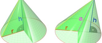
If you rotate a right triangle ABC around leg AB, then the resulting body is called a complete cone, leg AB is called the height of the cone. The straight line AB is called the generator of the cone, and point A is its vertex. When the leg BV rotates around the AB axis, a surface called the base of the cone is formed. The angle between the generatrix AG and the axis AB is the angle a of the inclination of the cone. The angle VAG between the generatrices AB and AG of the cone is called the cone angle; it is equal to 2a. If you cut off its upper part from a complete cone with a plane parallel to the base, then the resulting body will be a truncated cone (Fig. 206.6), which has two bases - upper and lower. Distance 001 between the bases is the height of the truncated cone. The drawing usually indicates three main dimensions of the cone (Fig. 206, c): the larger diameter D, the smaller diameter d and the height of the cone.
Using the formula tga = = (D - d)/(2l), you can determine the angle a of the cone, which is set on a lathe by turning the upper slide or shifting the tailstock. Sometimes the taper is specified as follows: K = (D - d)/l, i.e. the taper is the ratio of the difference in diameters to the length. In Fig. 206, d shows a cone for which K = (100 -90)/100 = 1/10, i.e., over a length of 10 mm, the diameter of the cone decreases by 1 mm. The taper and diameter of the cone are related by the equation d = = D - Kl, whence D = d + Kl.
If we take the ratio of the half-difference of the diameters of the cone to its length, we obtain a value called the slope of the cone M = (D - d)/(2l) (Fig. 206, e). Cone slope and taper are usually expressed in ratios of 1:10, 1:50 or 0.1:0.05, etc. In practice, the formula is used
Morse cones and metric cones are common in mechanical engineering. The Morse cone (Fig. 207) has seven numbers: 0, 1, 2, 3, 4, 5 and 6. Each number corresponds to a certain angle of inclination: the smallest 0, the largest 6. The angles of all cones are different. Metric cones have a taper of 4; 6; 80; 100; 120; 160 and 200; they have the same slope angle (Fig. 208).
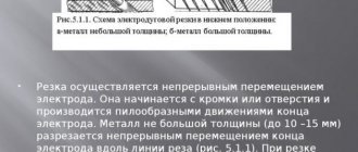
The processing of conical surfaces differs from the processing of cylindrical ones only by the feed angle of the cutter (Fig. 209), which is achieved by setting the machine. When the workpiece rotates, the tip of the cutter moves at an angle a (cone angle). On a lathe, cones are processed in several ways. Machining a cone using a wide cutter is shown in Fig. 210, a. In this case, the height of the cone should be no more than 20 mm. In addition, the cutting edge of the cutter is set at an angle a to the axis of rotation of the part exactly at the height of the centers (Fig. 210.6).
The simplest way to obtain conical surfaces is to shift the center line. This method is used only when processing surfaces in the centers by displacing the tailstock housing. When the tailstock body is shifted towards the worker (towards the tool holder), a conical surface is formed, in which the larger base of the part is directed towards the headstock (Fig. 211, a). When the tailstock body is displaced from the working one, the larger base is located towards the tailstock (Fig. 211.6). Transverse displacement of the tailstock body H = L - sina. With a slight shift in the angle of inclination of the cone a, we can assume that sinaa;tga, then H = L(D - d)/(2l). The displacement of the tailstock body is measured with a ruler (Fig. 211, c), the alignment of the centers can also be checked with a ruler (Fig. 211, d). However, when shifting the tailstock body, it should be taken into account that the shift is allowed by no more than 1/50 of the length of the part (Fig. 211, d). With a larger displacement, an incomplete fit between the center holes of the part and the centers is formed, which reduces the accuracy of the machined surface.
It is advisable to handle cones with a large angle a and a small height by turning the upper caliper. This method is used when processing the outer (Fig. 212, a) and internal (Fig. 212,6) cone. In this case, manual feed is carried out by turning the handle of the upper support. To rotate the upper caliper to the required angle during mechanical feed, markings are used on the flange of the rotating part of the caliper. If angle a is not specified in the drawing, it is calculated using the formula tga = (D - d)/(2l). The cutter is installed strictly in the center. Deviation from the straightness of the generatrix of the processed cone occurs when the cutter is installed above (Fig. 213.6) or below (Fig. 213.c) the center line.
Read also: Schottky barrier diode - what is it?
To obtain conical surfaces with a^ 10...12°, use a copy ruler (Fig. 214). A ruler 2 is installed on the plate 1, which is rotated to the required angle a around pin 3 and secured with a screw 6. The slider 4 is rigidly connected to the transverse part of the support 8 using a rod 7 and a clamp 5. The copying ruler must be installed parallel to the generatrix of the cone that needs to be obtained . The angle of rotation of the copy ruler is determined from the expression tga = (Z) - d)/(2l). If the divisions on the plate are indicated in millimeters, then the number of divisions C is H(D - d)/(2l), where R is the distance from the axis of rotation of the ruler to its end.
The cone, in which the length of the generatrix is greater than the stroke length of the upper carriage of the caliper, is ground by using longitudinal and transverse feeds (Fig. 215). In this case, the upper carriage must be rotated at an angle p relative to the center line: sinp = tga(Snp/S„+ 1), where oPr and S„ are the longitudinal and transverse feeds. To obtain the taper of the required shape, the cutter is installed strictly in the center.
The conical hole is processed in the following sequence. Drill a hole with a slightly smaller diameter than the diameter of the smaller base of the cone (Fig. 216), then drill out the hole with a drill. After this, the stepped hole is bored with a cutter. Another way to obtain a conical hole is by drilling a hole (Fig. 217, a), rough reaming (Fig. 217.6), semi-finishing (Fig. 217, c), finishing (Fig. 217, d).
Conical surfaces are controlled with inclinometers (Fig. 218, a), gauges (Fig. 218, b, c) and templates (Fig. 218, d). Conical holes are checked by the ledges and marks marked on the gauges (Fig. 219). If the end of the conical hole of the part coincides with the left end of the ledge, and the outer diameter coincides with one of the marks or is located between them, then the dimensions of the cone correspond to the specified ones.
Installations for automatic welding of longitudinal seams of shells - in stock!
High performance, convenience, ease of operation and reliability in operation.
Welding screens and protective curtains are in stock!
Radiation protection when welding and cutting. Big choice. Delivery throughout Russia!
How to sharpen using the method of displacement relative to the axis of centers?
This method allows turning only external conical surfaces on a turning unit. In the process of making a cone using this technique, a misalignment of the center holes occurs. This method does not have the particular precision with which a conical surface can be created.
Important!
This method allows the use of mechanical caliper feed, which makes it possible to use simple types of units. The off-axis method makes it possible to create a long Morse cone.
General information about cones
A conical surface is characterized by the following parameters (Fig. 4.31): smaller d and larger D diameters and the distance l between the planes in which circles with diameters D and d are located. Angle a is called the angle of inclination of the cone, and angle 2α is called the angle of the cone.
The ratio K= (D – d)/l is called taper and is usually indicated with a division sign (for example, 1:20 or 1:50) and in some cases with a decimal fraction (for example, 0.05 or 0.02).
The ratio Y= (D – d)/(2l) = tanα is called the slope.
How to turn a Morse taper on a lathe
Skip to content
In mechanical engineering, along with cylindrical ones, parts with conical surfaces in the form of external cones or in the form of conical holes are widely used. For example, the center of a lathe has two outer cones, one of which serves to install and secure it in the conical hole of the spindle; a drill, countersink, reamer, etc. also have an outer cone for installation and fastening. The adapter sleeve for fastening drills with a conical shank has an outer cone and a conical hole
The concept of a cone and its elements
Elements of a cone. If you rotate the right triangle ABC around the leg AB (Fig. 202, a), then a body ABG is formed, called a full cone
.
Line AB is called the axis or altitude of the cone
, line AB is called
the generator of the cone
.
Point A is the vertex of the cone
.
When the leg BV rotates around the axis AB, a circle surface is formed, called the base of the cone
.
The angle VAG between the lateral sides AB and AG is called the cone angle
and is denoted by 2α.
Half of this angle formed by the lateral side AG and the axis AB is called the cone angle
and is denoted α. Angles are expressed in degrees, minutes and seconds.
If we cut off its upper part from a complete cone with a plane parallel to its base (Fig. 202, b), we obtain a body called a truncated cone
.
It has two bases, upper and lower. The distance OO1 along the axis between the bases is called the height of the truncated cone
. Since in mechanical engineering we mostly have to deal with parts of cones, i.e. truncated cones, they are usually simply called cones; From now on we will call all conical surfaces cones.
The connection between the elements of the cone. The drawing usually indicates three main dimensions of the cone: the larger diameter D, the smaller diameter d and the height of the cone l (Fig. 203).
Sometimes the drawing indicates only one of the cone diameters, for example, the larger D, the cone height l and the so-called taper. Taper is the ratio of the difference between the diameters of a cone and its length. Let us denote the taper by the letter K, then
If the cone has dimensions: D = 80 mm, d = 70 mm and l = 100 mm, then according to formula (10):
This means that over a length of 10 mm the diameter of the cone decreases by 1 mm or for every millimeter of the length of the cone the difference between its diameters changes by
Sometimes on the drawing, instead of the angle of the cone, the slope of the cone
. The slope of the cone shows the extent to which the generatrix of the cone deviates from its axis. The slope of the cone is determined by the formula
where tan α is the slope of the cone; D is the diameter of the large base of the cone in mm; d is the diameter of the small base of the cone in mm;
l is the height of the cone in mm.
Using formula (11), you can use trigonometric tables to determine the angle a of the cone.
Cone slope and taper are usually expressed as a simple fraction, for example: 1: 10; 1:50, or a decimal fraction, for example, 0.1; 0.05; 0.02, etc.
Methods for producing conical surfaces on a lathe
On a lathe, processing of conical surfaces is carried out in one of the following ways: a) turning the upper part of the support; b) transverse displacement of the tailstock body; c) using a cone ruler;
d) using a wide cutter.
Machining conical surfaces by turning the upper part of the caliper
When making short external and internal conical surfaces with a large slope angle on a lathe, you need to rotate the upper part of the support relative to the axis of the machine at an angle α of the cone slope (see Fig. 204). With this method of operation, feeding can only be done by hand, rotating the handle of the lead screw of the upper part of the support, and only the most modern lathes have a mechanical feed of the upper part of the support.
To set the upper part of the caliper 1 to the required angle, you can use the divisions marked on the flange 2 of the rotating part of the caliper (Fig. 204). If the slope angle α of the cone is specified according to the drawing, then the upper part of the caliper is rotated together with its rotating part by the required number of divisions indicating degrees. The number of divisions is counted relative to the mark marked on the bottom of the caliper.
If the angle α is not given in the drawing, but the larger and smaller diameters of the cone and the length of its conical part are indicated, then the value of the caliper rotation angle is determined by formula (11)
Methods for processing conical surfaces
When processing shafts, transitions between surfaces that have a conical shape are often encountered. If the length of the cone does not exceed 50 mm, then it can be processed by cutting in with a wide cutter. The angle of inclination of the cutting edge of the cutter in plan must correspond to the angle of inclination of the cone on the machined part. The cutter is given a transverse feed movement.
To reduce the distortion of the generatrix of the conical surface and reduce the deviation of the angle of inclination of the cone, it is necessary to install the cutting edge of the cutter along the axis of rotation of the workpiece.
It should be taken into account that when processing a cone with a cutter with a cutting edge more than 15 mm long, vibrations may occur, the higher the level of which, the longer the length of the workpiece, the smaller its diameter, the smaller the angle of inclination of the cone, the closer the cone is to the middle of the part, the greater the overhang cutter and less strength of its fastening. As a result of vibrations, marks appear on the treated surface and its quality deteriorates. When processing hard parts with a wide cutter, there may be no vibrations, but the cutter may shift under the influence of the radial component of the cutting force, which leads to a violation of the cutter’s adjustment to the required angle of inclination. (The offset of the cutter depends on the processing mode and the direction of feed movement.)
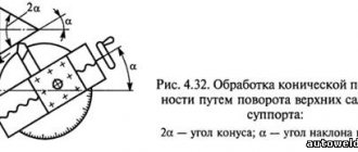
Conical surfaces with large slopes can be processed by turning the upper slide of the support with the tool holder (Fig. 4.32) at an angle α equal to the angle of inclination of the cone being processed. The cutter is fed manually (using the handle for moving the upper slide), which is a disadvantage of this method, since the unevenness of the manual feed leads to an increase in the roughness of the machined surface. Using this method, conical surfaces are processed, the length of which is commensurate with the stroke length of the upper slide.
A long conical surface with an angle α= 8. 10° can be machined by shifting the tailstock (Fig. 4.33)
At small angles sinα ≈ tanα
where L is the distance between centers; D - larger diameter; d—smaller diameter; l is the distance between the planes.
If L = l, then h = (Dd)/2.
The tailstock displacement is determined by the scale marked on the end of the base plate on the flywheel side and the mark on the end of the tailstock housing. The scale division is usually 1 mm. If there is no scale on the base plate, the tailstock displacement is measured using a ruler attached to the base plate.
To ensure the same taper of a batch of parts processed by this method, it is necessary that the dimensions of the workpieces and their center holes have minor deviations. Since misalignment of machine centers causes wear on the center holes of the workpieces, it is recommended to pre-machin the conical surfaces, then correct the center holes and then perform final finishing. To reduce the breakdown of the center holes and the wear of the centers, it is advisable to make the latter with rounded tops.
Read also: Cross-sectional area of the strip
Quite common is the processing of conical surfaces using copying devices. A plate 7 (Fig. 4.34, a) with a tracing ruler 6 is attached to the machine bed, along which a slider 4 moves, connected to the support 1 of the machine by a rod 2 using a clamp 5. To freely move the support in the transverse direction, it is necessary to disconnect the screw for the transverse feed movement. When the caliper 1 moves longitudinally, the cutter receives two movements: longitudinal from the caliper and transverse from the tracing ruler 6. The transverse movement depends on the angle of rotation of the tracing ruler 6 relative to the axis of rotation 5. The angle of rotation of the ruler is determined by the divisions on plate 7, fixing the ruler with bolts 8. The movement of the cutter feed to the cutting depth is carried out by the handle for moving the upper slide of the caliper. External conical surfaces are processed with through cutters.
Using a wide angle cutter
To work with workpieces on a lathe, there is a wide angle cutter. With this help it is very convenient to grind cone-shaped surfaces of short length. Using this technique it is possible to create cones with different angles. The specified angle of the conical surface is corrected by sharpening the edge of the cutter, or by installing the cutter at the required angle to the workpiece.
All considered cone manufacturing methods have their own advantages and disadvantages. And the choice of method for creating conical surfaces depends on the equipment, the characteristics that the resulting part must have and the skills of the craftsman.
Methods for processing internal conical surfaces
Processing of the inner conical surface 4 of the workpiece (Fig. 4.34, b) is carried out using a copier 2 installed in the tailstock quill or in the turret head of the machine. In the tool holder of the transverse support, a device 1 with a tracking roller 3 and a pointed cutter is installed. When the caliper moves transversely, the follower roller 3, in accordance with the profile of the follower 2, receives longitudinal movement, which is transmitted through the device 1 to the cutter. Internal conical surfaces are processed with boring cutters.
To obtain a conical hole in a solid material, the workpiece is first pre-processed (drilled, bored), and then finally (reamed). Reaming is performed sequentially with a set of conical reamers. The diameter of the pre-drilled hole is 0.5. 1 mm less than the lead-in diameter of the reamer.
If a high-precision conical hole is required, then before deployment it is processed with a conical countersink, for which a hole with a diameter of 0.5 mm less than the diameter of the cone is drilled in solid material, and then a countersink is used. To reduce the allowance for countersinking, step drills of different diameters are sometimes used.
Center hole machining
In parts such as shafts, center holes are often made, which are used for subsequent turning and grinding of the part and for restoring it during operation. Based on this, alignment is performed especially carefully.
The center holes of the shaft must be on the same axis and have identical conical holes at both ends, regardless of the diameters of the end journals of the shaft. Failure to comply with these requirements reduces the processing accuracy and increases the wear of centers and center holes.
The designs of the center holes are shown in Fig. 4.35. The most common are center holes with a cone angle of 60°. Sometimes in heavy shafts this angle is increased to 75 or 90°. To ensure that the top of the center does not rest against the workpiece, cylindrical recesses with a diameter d are made in the center holes.
To protect against damage, reusable center holes are made with a safety chamfer at an angle of 120° (Fig. 4.35, b).
Various methods are used to machine center holes in small workpieces. The workpiece is secured in a self-centering chuck, and a drill chuck with a centering tool is inserted into the tailstock quill. Large center holes are processed first with a cylindrical drill (Fig. 4.36, a), and then with a single-tooth (Fig. 4.36, b) or multi-tooth (Fig. 4.36, c) countersink. Center holes with a diameter of 1.5. 5 mm is processed with combination drills without a safety chamfer (Fig. 4.36, d) and with a safety chamfer (Fig. 4.36, e).
Center holes are machined with the workpiece rotating; The feeding movement of the centering tool is carried out manually (from the tailstock flywheel). The end in which the center hole is processed is pre-cut with a cutter.
The required size of the center hole is determined by the recess of the centering tool, using the tailstock flywheel dial or quill scale. To ensure the alignment of the center holes, the part is pre-marked, and long parts are supported with a steady rest during alignment.
The center holes are marked using a square.
After marking, the center hole is marked. If the shaft journal diameter does not exceed 40 mm, then the center hole can be punched without preliminary marking using the device shown in Fig. 4.37. The body 1 of the device is installed with the left hand at the end of the shaft 3 and the center of the hole is marked with a hammer blow on the center punch 2.
If during operation the conical surfaces of the center holes are damaged or unevenly worn, they can be corrected with a cutter. In this case, the upper carriage of the caliper is rotated through the cone angle.
Ways to distinguish the cartridge fairing in a drill
The Morse fairing can be manufactured using different methods and is not always highly interchangeable. The size of the cone is indicated by numbers. Currently, sanders are available in increments of 5, and their standard size ranges from 10 to 80. As a rule, the designations are as follows:
- ISO20
- NMTB30
- BT40
A distinctive feature is the standard size of the conical section.
Typological characteristics of conical dimensions:
- D is an indicator of the basic size of the cone socket.
- L – penetration depth indicator
These sizes are the same for all countries in the world that use the metric system. The diameter of the flange section DF approximately corresponds to all design varieties of the product.
Nowadays, most cones are produced with a replaceable adapter, this makes it possible to combine equipment with different standards. There are several features of the flange section, which have a letter designation: A, B, C, D, E, F. The dimensional part of the proluvium itself is designated as follows:
- minimum length 25 mm
- maximum – 160 mm (for example, model HSK-A73)
Inspection of conical surfaces
The taper of the outer surfaces is measured with a template or a universal inclinometer. For more accurate measurements, bushing gauges are used (Fig. 4.38), with which they check not only the angle of the cone, but also its diameters. Two or three marks are applied to the treated surface of the cone with a pencil, then a sleeve gauge is put on the cone being measured, lightly pressing on it and turning it along the axis. With a correctly executed cone, all marks are erased, and the end of the conical part is located between marks A and B.
When measuring conical holes, a plug gauge is used. The correct machining of a conical hole is determined (as when measuring external cones) by the mutual fit of the surfaces of the part and the plug gauge. If a thin layer of paint applied to a plug gauge is erased at a small diameter, then the cone angle in the part is large, and if at a large diameter, the angle is small.