GOST 20872-80
GOST 20872-80 Group G23
INTERSTATE STANDARD
ASSEMBLY TURNING CUTTERS FOR CONTOUR TURNING WITH MECHANICAL FASTENING OF MULTIFEDAL CARBIDE INSERTS
Design and dimensions
Contour turning tools with mechanically clamped cemented carbide indexible inserts. Design and dimensions
MKS 25.100.10 OKP 39.2192
Date of introduction 1982-01-01
ENTERED INTO EFFECT by the Decree of the USSR State Committee on Standards dated November 17, 1980 N 5382 INSTEAD GOST 20872-75 REISSUE.
1. This standard applies to cutters for contour turning with mechanical fastening of polyhedral carbide inserts, intended for operation on numerically controlled machines and on universal machines.
2. Cutters must be made of the following types:
1 - cutters with parallelogram-shaped cutting plates with a leading angle = 93°, right and left:
2 - the same with a lead angle = 63°;
3 — cutters with cutting plates of regular triangular shape with a leading angle = 93°, right and left;
4 - the same, with a leading angle = 63°.
3. The main dimensions of the cutters must correspond to those indicated in Figures 1-4 and in Tables 1-4.
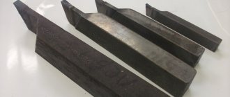
Type 1
1
- holder;
2
— cutting plate according to GOST 19062-80;
3
— support plate according to GOST 19079-80;
4
- sticking;
5
- screw;
6
— pin Fig.1
Damn.2. Type 2
Type 2
1
- holder;
2
— cutting plate according to GOST 19062-80;
3
— support plate according to GOST 19079-80;
4
- sticking;
5
- screw;
6
— pin Fig.2
Table 1
| mm | ||||||||||||
| Right incisors | Left incisors | Cutter section | Pos.2 . Cutting insert according to GOST 19062-80 Col. 1 | Pos.3 . Support plate according to GOST 19079-80 Col. 1 | ||||||||
| Designation | Applicability | Designation | Applicability | Right | Left | Right | Left | |||||
| Designation | ||||||||||||
| 2101-0601 | 2101-0602 | 20×20 | 20 | 27 | 25 | 150 | 08116-170405-130 | 08116-170405-230 | 741-1704-1 | 741-1704-2 | ||
| 2101-0603 | 2101-0604 | 08116-170410-130 | 08116-170410-230 | |||||||||
| 2101-0605 | 2101-0606 | 08116-170410-136 | 08116-170410-236 | |||||||||
| 2101-0607 | 2101-0608 | 08116-170415-130 | 08116-170415-230 | |||||||||
| 2101-0611 | 2101-0612 | 08116-170415-136 | 08116-170415-236 | |||||||||
| 2101-0637 | 2101-0638 | 25×25 | 25 | 32 | 32 | 08116-190605-130 | 08116-190605-230 | 741-1904-1 | 741-1904-2 | |||
| 2101-0641 | 2101-0642 | 08116-190610-130 | 08116-190610-230 | |||||||||
| 2101-0643 | 2101-0644 | 08116-190610-136 | 08116-190610-236 | |||||||||
| 2101-0645 | 2101-0646 | 08116-190615-130 | 08116-190615-230 | |||||||||
| 2101-0647 | 2101-0648 | 08116-190615-136 | 08116-190615-236 | |||||||||
| 2101-0651 | 2101-0652 | 32×25 | 32 | 39 | 170 | 08116-190605-130 | 08116-190605-230 | |||||
| 2101-0653 | 2101-0654 | 08116-190610-130 | 08116-190610-230 | |||||||||
| 2101-0655 | 2101-0656 | 08116-190610-136 | 08116-190610-236 | |||||||||
| 2101-0657 | 2101-0658 | 08116-190615-130 | 08116-190615-230 | |||||||||
| 2101-0661 | 2101-0662 | 08116-190615-136 | 08116-190615-236 | |||||||||
| 2101-0663 | 2101-0664 | 32×32 | 40 | 08116-190605-130 | 08116-190605-230 | |||||||
| 2101-0665 | 2101-0666 | 08116-190610-130 | 08116-190610-230 | |||||||||
| 2101-0667 | 2101-0668 | 08116-190610-136 | 08116-190610-236 | |||||||||
| 2101-0671 | 2101-0672 | 08116-190615-130 | 08116-190615-230 | |||||||||
| 2101-0673 | 2101-0674 | 08116-190615-136 | 08116-190615-236 | |||||||||
| 2101-0675 | 2101-0676 | 40×32 | 40 | 47 | 200 | 08116-190605-130 | 08116-190605-230 | |||||
| 2101-0677 | 2101-0678 | 08116-190610-130 | 08116-190610-230 | |||||||||
| 2101-0681 | 2101-0682 | 08116-190610-136 | 08116-190610-236 | |||||||||
| 2101-0683 | 2101-0684 | 08116-190615-130 | 08116-190615-230 | |||||||||
| 2101-0685 | 2101-0686 | 08116-190615-136 | 08116-190615-236 | |||||||||
An example of a symbol for a type 1 cutter, cross-section = 25×25 mm, length = 150 mm, equipped with a cutting insert 08116-190610-130, right:
Cutter 2101-0641 GOST 20872-80
table 2
| mm | ||||||||||||
| Right incisors | Left incisors | Cutter section | Pos.2 . Cutting insert according to GOST 19062-80 Col. 1 | Pos.3 . Support plate according to GOST 19079-80 Col. 1 | ||||||||
| Designation | Applicability | Designation | Applicability | Right | Left | Right | Left | |||||
| Designation | ||||||||||||
| 2101-0757 | 2101-0758 | 20×20 | 20 | 27 | 25 | 150 | 08116-170405-130 | 08116-170405-230 | 741-1704-1 | 741-1704-2 | ||
| 2101-0761 | 2101-0762 | 08116-170410-130 | 08116-170410-230 | |||||||||
| 2101-0763 | 2101-0764 | 08116-170410-136 | 08116-170410-236 | |||||||||
| 2101-0765 | 2101-0766 | 08116-170415-130 | 08116-170415-230 | |||||||||
| 2101-0767 | 2101-0768 | 08116-170415-136 | 08116-170415-236 | |||||||||
| 2101-0795 | 2101-0796 | 25×25 | 25 | 32 | 27 | 08116-190605-130 | 08116-190605-230 | 741-1904-1 | 741-1904-2 | |||
| 2101-0797 | 2101-0798 | 08116-190610-130 | 08116-190610-230 | |||||||||
| 2101-0801 | 2101-0802 | 08116-190610-136 | 08116-190610-236 | |||||||||
| 2101-0803 | 2101-0804 | 08116-190615-130 | 08116-190615-230 | |||||||||
| 2101-0805 | 2101-0806 | 08116-190615-136 | 08116-190615-230 | |||||||||
| 2101-0807 | 2101-0808 | 32×25 | 32 | 39 | 170 | 08116-190605-130 | 08116-190605-230 | |||||
| 2101-0811 | 2101-0812 | 08116-190610-130 | 08116-190610-230 | |||||||||
| 2101-0813 | 2101-0814 | 08116-190610-136 | 08116-190610-230 | |||||||||
| 2101-0815 | 2101-0816 | 08116-190615-130 | 08116-190615-230 | |||||||||
| 2101-0817 | 2101-0813 | 08116-190615-136 | 08116-190615-236 | |||||||||
| 2101-0821 | 2101-0822 | 32×32 | 32 | 08116-190605-130 | 08116-190605-230 | |||||||
| 2101-0823 | 2101-0824 | 08116-190610-130 | 08116-190610-230 | |||||||||
| 2101-0825 | 2101-0826 | 08116-190610-136 | 08116-190610-230 | |||||||||
| 2101-0827 | 2101-0828 | 08116-190615-130 | 08116-190615-230 | |||||||||
| 2101-0831 | 2101-0832 | 08116-190615-136 | 08116-190615-236 | |||||||||
| 2101-0833 | 2101-0834 | 40×32 | 40 | 47 | 200 | 08116-190605-130 | 08116-190605-230 | |||||
| 2101-0835 | 2101-0836 | 08116-190610-130 | 08116-190610-230 | |||||||||
| 2101-0837 | 2101-0838 | 08116-190610-136 | 08116-190610-236 | |||||||||
| 2101-0841 | 2101-0842 | 08116-190615-130 | 08116-190615-230 | |||||||||
| 2101-0843 | 2101-0844 | 08116-190615-136 | 08116-190615-236 | |||||||||
An example of a symbol for a type 2 cutter, cross-section = 25×25 mm, length = 150 mm, equipped with a cutting insert 08116-190610-130, right:
Cutter 2101-0797 GOST 20872-80
I. TECHNICAL REQUIREMENTS
I. TECHNICAL REQUIREMENTS
1. As the cutting part of the cutter, soldered carbide inserts should be used from grades of carbide of application groups P01...P50, M10...M40, K01...K40 according to GOST 3882.
It is allowed to use plates in accordance with other technical documentation approved in the prescribed manner.
(Changed edition, Amendment No. 6).
2. Holders for turning, scoring, boring type 2 and boring holder cutters with a height of more than 12 mm must be made of steel grade 45 or 50 according to GOST 1051 group B for general purpose, and holders of the same cutters with a height of up to 12 mm incl. — made of steel grade 40X according to GOST 1051 group B for general purpose.
It is allowed to use steel grades 45 and 50 according to GOST 1050 and grade 40X according to GOST 4543.
The holders of planing and scoring cutters must be made of steel grade 45 or 50 according to GOST 1050, and the holders of planing and turning cutting and slotting cutters and turning boring cutters of version 1 should be made of steel grade 40X according to GOST 4543 and steel grade 45 or 50 according to GOST 1050 .
It is allowed to manufacture cutter holders from structural powder steels with a density of at least 6.9 g/cm.
(Changed edition, Amendment No. 3, 4, 5, 6).
3. Protrusion of the cutting insert relative to the cutter holder is allowed. The amount of protrusion of the insert should not exceed the thickness of the cutting insert:
| up to 5 mm | 0.5 mm | ||
| over 5 mm | 1.0 mm | ||
The amount of plate protrusion for cutting, slotting and revolving cutters should not exceed 0.5 mm.
The depth of the groove for the cutting plate on the cutter holders should be 0.5-0.75 of the thickness of the cutting plate. For cutters with a holder cross-section equal to 12x12 mm or with a holder diameter equal to or less than 12 mm, the groove depth can be equal to the thickness of the plate (Fig. 1).
Damn.1
When diamond sharpening, overhang of carbide plates of up to 0.8 mm is allowed.
The depth of the groove of the parting cutters must be equal to the thickness of the plate.
Solders of P102 and PrMNMTs 68-4-2 brands should be used as solder.
The use of solder grades PrANMts 06-4-2 and P100 is allowed.
The solder layer should be no more than 0.35 mm thick.
In the seam around the perimeter and in the corners of the seam, single places without soldering (pores) are allowed.
Breaks in the solder seam between the supporting surfaces of the cutting insert and holder should not exceed 10% of the visible length of the solder seam on through and scoring cutters and 5% on slotting and parting cutters. Solder breaks under the main cutting edge are not allowed.
On the side supporting surfaces of the cutting insert, the total length of the gaps should not exceed 50% of the length of the solder seam. Solder residues are allowed on the holder under the plate on the rear and front surfaces of the cutters if these surfaces extend beyond the holder.
(Changed edition, Amendment No. 4, 5, 6).
4. Cracks, chipping and traces of solder are not allowed on the front and back surfaces forming the cutting edge and rounding of the apex.
On non-working edges and corners, chipping is allowed, the magnitude of which should not exceed those indicated in Table 1a.
Table 1a
mm
| Insert thickness | Allowable chip size | |
| over | before | |
| 2 | 0.3x0.5 | |
| 2 | 5 | 0.4x0.8 |
| 5 | 10 | 0.6x1.2 |
| 10 | 0.8x2.0 | |
(Changed edition, Amendment No. 4, 6).
5. The front and rear surfaces forming the main cutting edge, including the curved section at the tip of the cutter, must be subjected to finishing operations.
The curved front surface, shaped like a hole, is not subject to finishing.
For cutters, the front surface of which is formed by two intersecting planes, only the surface adjacent to the main cutting edge should be polished.
6. The roughness parameters of cutters according to GOST 2789 should not exceed the specified values, microns, of the front and rear surfaces and the curved surface at the apex:
| subjected to fine-tuning | 0,4 | ||
| not subject to fine-tuning | 0,8 | ||
| auxiliary rear surface | 1,6 | ||
| supporting surface | 3,2 | ||
| side and top surfaces of holders of boring holder and turret cutters | 3,2 | ||
| other treated surfaces | 10 | ||
It is allowed, by agreement with the consumer, not to sharpen and fine-tune cutters on the front surfaces, and cutting cutters and on auxiliary rear surfaces.
(Changed edition, Amendment No. 6, 7).
7, 8. (Excluded, Amendment No. 4).
9. The connection between the main and auxiliary cutting edges should be smooth and correspond to the curve described by the radius. Abrupt transitions are not allowed.
10. The surfaces of the cutter holder must have a protective or protective-decorative coating in accordance with GOST 9.301 and GOST 9.306.
Protective or protective-decorative coatings should not violate the flatness of the supporting surface of the incisors.
It is allowed, by agreement with the consumer, to produce cutter holders without a protective or protective-decorative coating.
(Changed edition, Amendment No. 7).
11. Maximum deviations in the dimensions of turning and planing cutter holders must not exceed the specified values, microns:
| heights and widths of cold-drawn steel cutters with one machined support surface | h 16 | ||
| cutter heights made of hot-rolled steel with one machined bearing surface | h 17 | ||
| height, width and diameter of turret, turning, bent and boring holder cutters with all machined surfaces | h 11 | ||
| boring cutters with round holder section | h 9 | ||
(Changed edition, Amendment No. 4).
12. (Deleted, Amendment No. 4).
13. For cutters in which the height of the cutting edge corresponds to the height of the holder, the maximum deviations of the tip of the cutting edge should not exceed: tolerance ± IT 14 - for turning cutters, ± IT 11 - for boring cutters.
For cutters in which the height of the cutting edge does not correspond to the height of the holder, the maximum deviations of the tip of the cutting edge are not determined.
For cutters with a symmetrical cutting part, the maximum deviations from the symmetry of the cutting inserts (for wide cutters) or tips (for pointed cutters) relative to the width of the holder should not exceed tolerance IT 14.
The maximum deviations from the symmetry of the cutter tip relative to the width of the cutting plate should not exceed half of the IT 15 tolerance (Fig. 2).
Damn.2
(Changed edition, Amendment No. 4).
14. (Deleted, Amendment No. 4).
15. Maximum deviations in the width of the working part of cutting and slotting cutters should not exceed those indicated in Table 1.
Table 1
mm
| Nominal working width | Maximum deviation of the width of the working part of the cutter | |
| slotted | cutting | |
| 3, 4, 5 | +0,1 -0,35 | +0,2 -0,5 |
| 6, 8, 10 | +0,1 -0,4 | +0,2 -0,5 |
| 12, 16, 18 | +0,2 -0,6 | +0,2 -0,6 |
| 20, 25 | +0,2 -0,7 | +0,2 -0,7 |
(Changed edition, Amendment No. 3, 5).
16. The maximum deviations of cutters up to 50 mm long should not exceed a tolerance of ±IT 16, and for cutters with a length of more than 50 mm, a tolerance of ±2 IT 16.
(Changed edition, Amendment No. 4).
17. Permissible deviations for the length of the drawn part of slotting, cutting and boring cutters should not exceed:
| for cutters with drawn length up to 20 mm | ±1 mm | ||
| for cutters with a drawn-out length of more than 20 to 50 mm | mm | ||
| for cutters with a drawn-out length of more than 50 mm | mm | ||
18. (Deleted, Amendment No. 6).
19. The flatness tolerance of the lower supporting surface of the cutter holder must correspond to the 10th degree of accuracy according to GOST 24643. Convexity is not allowed.
It is allowed to manufacture cutters with a flatness tolerance of the lower supporting surface of the cutter holder, no more than, mm: 0.1 - for cutters up to 50 mm long; 0.2 - for incisors over 50 mm long.
(Changed edition, Amendment No. 6, 7).
20. The straightness tolerance of the sides of the holder of turning and planing cutters should not exceed 1 mm per 100 mm of length.
In the case of cutting on presses, jams are allowed at the end of the holder of turning and planing cutters, the dimensions of which should not exceed those indicated in Table 2.
table 2
mm
| Height of cutter holder, | Zamin | |
| along the holder | by holder height | |
| 6-12 | 2 | 0,8 |
| 16; 20 | 3 | 1,0 |
| 25; 32 | 5 | 1,5 |
| 40; 50; 63 | 7 | 2,0 |
(Changed edition, Amendment No. 3, 4, 6).
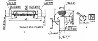
21. Maximum deviations of the angles of the cutting part of the incisors (Fig. 3) should not exceed:
Damn.3
| front main angle up to 10° | ±1° | ||
| over 10° | ±2° | ||
| rear main angle () up to 10° | ±1° | ||
| over 10° | ±2° | ||
| main plan angle | ±2° | ||
| auxiliary lead angle () | |||
| up to 2° | ±0°30′ | ||
| at over 2° to 5° | ±1° | ||
| at over 5° | ±2° | ||
| cutting edge angle () | ±1° | ||
| main lead-in angle and back auxiliary lead-in angle for parting and slotting cutters | ±0°30′ | ||
22. Maximum deviations from the perpendicularity of the side surfaces relative to the supporting surface of the cutter should not exceed:
| for cutters machined only on the supporting surface | ±2° |
| for cutters with all machined surfaces | ±1° |
| for boring cutters | ±0°30′ |
| for slotting and parting cutters | ±1° |
21, 22. (Changed edition, Amendment No. 4).
22a. The average service life of cutters must be at least 45 minutes, the established service life period must be at least 20 minutes, under the operating conditions specified in the general machine-building cutting standards for turning and rotary work.
(Introduced additionally, Amendment No. 5).
22b. The criterion for dullness is the achievement of flank wear indicated in Table 4.
Table 4*
_________________ * Table 3. (Excluded, Amendment No. 5).
| Cutter type | Processed material | Allowable wear on the rear surface, mm |
| Pass-through straight and bent, push-through persistent | Steel | 0,8 |
| Cast iron | 1,2 | |
| Boring | Steel | 0,6 |
| Cast iron | 1,0 | |
| Cut-off and slotted | Steel, cast iron | 0,8 |
(Changed edition, Amendment No. 6).
Continuation of Table 4
| Cutter type | Processed material | Allowable wear on the rear surface, mm |
| Threaded for pitch: | ||
| up to 3 mm | Steel, cast iron | 0,2 |
| St. 3 mm | Steel, cast iron | 0,4 |
| Planing | Steel, cast iron | 0,8 |
22c. On one of the sides of each cutter the following must be applied:
manufacturer's trademark;
width of the cutting part for slotted cutters;
grade of hard alloy;
cutter designation (last four digits);
image of the state Quality Mark when it is assigned in the manner established by the USSR State Standard.
22g. Transport marking and marking of consumer packaging - in accordance with GOST 18088.
22d. Internal packaging option VU-1 - according to GOST 9.014.
22nd Other packaging requirements are in accordance with GOST 18088.
22c-22e. (Introduced additionally, Amendment No. 6).
23, 24. (Excluded, Amendment No. 4).
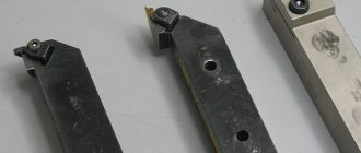
Damn.3. Type 3
Type 3
1
- holder;
2
— cutting plate according to GOST 19046-80;
3
— support plate according to GOST 19073-80;
4
- wedge;
5
- screw;
6
— pin Drawing 3
Table 3
| mm | ||||||||||
| Right incisors | Left incisors | Cutter section | Pos.2 . Cutting insert according to GOST 19046-80 Col. 1 | Pos.3 . Support plate according to GOST 19073-80 Col. 1 | ||||||
| Designation | Applicability | Designation | Applicability | |||||||
| Designation | ||||||||||
| 2103-0671 | 2103-0672 | 16×16 | 16 | 19 | 20 | 125 | 01114-160304 | 701-1604 | ||
| 2103-0673 | 2103-0674 | 01114-160308 | ||||||||
| 2103-0675 | 2103-0676 | 01114-160312 | ||||||||
| 2103-0677 | 2103-0678 | 01114-160408 | 701-1603 | |||||||
| 2103-0681 | 2103-0682 | 01114-160412 | ||||||||
| 2103-0695 | 2103-0696 | 20×20 | 20 | 24 | 25 | 150 | 01114-220408 | 701-2204 | ||
| 2103-0697 | 2103-0698 | 01114-220412 | ||||||||
| 2103-0701 | 2103-0702 | 01114-220416 | ||||||||
| 2103-0711 | 2103-0712 | 25×25 | 25 | 29 | 32 | 01114-220408 | ||||
| 2103-0713 | 2103-0714 | 01114-220412 | ||||||||
| 2103-0715 | 2103-0716 | 01114-220416 | ||||||||
| 2103-0717 | 2103-0718 | 32×25 | 32 | 36 | 170 | 01114-220408 | ||||
| 2103-0721 | 2103-0722 | 01114-220412 | ||||||||
| 2103-0723 | 2103-0724 | 01114-220416 | ||||||||
| 2103-0725 | 2103-0726 | 32×32 | 40 | 01114-270612 | 701-2704 | |||||
| 2103-0727 | 2103-0728 | 01114-270616 | ||||||||
| 2103-0731 | 2103-0732 | 40×32 | 40 | 44 | 200 | 01114-270612 | ||||
| 2103-0733 | 2103-0734 | 01114-270616 | ||||||||
An example of a symbol for a type 3 cutter, cross-section = 25×25 mm, length = 150 mm, equipped with a cutting insert 01114-220412, right:
Cutter 2103-0713 GOST 20872-80
Selection rules
The first thing you should focus on when choosing a groove turning tool is a drawing of the finished product, which indicates both the dimensions and shape of the grooves, as well as the tolerances for the accuracy of their geometric parameters. Naturally, the choice of cutter and its geometric parameters is influenced by the material from which the workpiece is made.
External groove cutter
When forming grooves on small parts, it is especially important to maintain a low cutting force, which minimizes the distortion that occurs during processing. Compliance with this requirement is ensured by the sharp sharpening of the groove tool, which, however, can lead to its breakage if the carbide plate material and cutting conditions are selected incorrectly - the rotation speed of the workpiece and the feed rate.
When choosing a groove cutter, you should also take into account the shape of its cutting edge, which can be straight and sharpened with a small radius. Naturally, you should not choose a product with a curved sharpening of the cutting edge if the bottom of the groove, according to the provided drawing, should be straight.
Internal groove cutter
Damn.4. Type 4
Type 4
1
- holder;
2
— cutting plate according to GOST 19046-80;
3
— support plate according to GOST 19073-80;
4
- wedge;
5
- screw;
6
— pin Fig.4
Table 4
| mm | ||||||||||
| Right incisors | Left incisors | Cutter section | Pos.2 . Cutting insert according to GOST 19046-80 Col. 1 | Pos.3 . Support plate according to GOST 19073-80 Col. 1 | ||||||
| Designation | Applicability | Designation | Applicability | |||||||
| Designation | ||||||||||
| 2101-0915 | 2101-0916 | 16×16 | 16 | 19 | 9 | 125 | 01114-160304 | 701-1604 | ||
| 2101-0917 | 2101-0918 | 01114-160308 | ||||||||
| 2101-0921 | 2101-0922 | 01114-160312 | ||||||||
| 2101-0923 | 2101-0924 | 01114-160408 | 701-1603 | |||||||
| 2101-0925 | 2101-0926 | 01114-160412 | ||||||||
| 2101-0941 | 2101-0942 | 20×20 | 20 | 24 | 11 | 150 | 01114-220408 | 701-2204 | ||
| 2101-0943 | 2101-0944 | 01114-220412 | ||||||||
| 2101-0945 | 2101-0946 | 01114-220416 | ||||||||
| 2101-0955 | 2101-0956 | 25×25 | 25 | 29 | 15 | 01114-220408 | ||||
| 2101-0957 | 2101-0958 | 01114-220412 | ||||||||
| 2101-0961 | 2101-0962 | 01114-220416 | ||||||||
| 2101-0963 | 2101-0964 | 32×25 | 32 | 36 | 170 | 01114-220408 | ||||
| 2101-0965 | 2101-0966 | 01114-220412 | ||||||||
| 2101-0967 | 2101-0968 | 01114-220416 | ||||||||
| 2101-0971 | 2101-0972 | 32×32 | 01114-270612 | 701-2704 | ||||||
| 2101-0973 | 2101-0974 | 01114-270616 | ||||||||
| 2101-0975 | 2101-0976 | 40×32 | 40 | 44 | 200 | 01114-270612 | ||||
| 2101-0977 | 2101-0978 | 01114-270616 | ||||||||
An example of a symbol for a type 4 cutter, cross-section =25×25 mm, =150 mm, equipped with a cutting insert 01114-220412, right:
Cutter 2101-0957 GOST 20872-80
4. The geometric parameters of the cutters and the design of their parts are given in the Appendix.
5. Technical requirements - according to GOST 26613-85.
3. ACCEPTANCE RULES
3.1. Acceptance inspection and periodic testing must be carried out to verify that cutters and inserts comply with the requirements of this standard.
3.2. All cutters (inserts) must be subject to acceptance control for compliance with the requirements of clauses 1.1-1.4, 2.7, 2.10, 2.13; for compliance with the requirements of paragraphs 1.1-1.4 (in terms of surface roughness of the working part and body), 2.6, 2.8, 2.9, 2.11, 2.12 - 20% of cutters (inserts) from the batch, but not less than 10 pieces. The batch must consist of cutters (inserts) of the same type, simultaneously presented for acceptance according to one document.
3.3. If during acceptance control it is determined that there is non-compliance with the requirements of the standard for more than one controlled indicator, then the batch is not accepted. If non-compliance with the requirements of the standard is established for one of the controlled indicators, then repeated control is carried out on a double number of cutters (inserts). If there are defects in the re-sampling, the batch will not be accepted.
3.4. Cutters (inserts) that have passed acceptance control, in an amount of at least 5 pieces, must be subjected to periodic testing for compliance with the requirements of clause 2.14. at least once every two years. It is allowed to carry out tests at the consumer's site under production conditions.
3.3; 3.4. (Changed edition, Amendment No. 2).
Labeling and manufacturers
The description of groove turning tools will be incomplete without mentioning the markings, which determine the composition of the material of their cutting part. For example, the T5K10 cutter is made of a hard alloy of the titanium-tungsten group, which contains 5% titanium carbide and 10% cobalt. The markings of products made from other materials are deciphered in a similar way.
The most famous manufacturers of grooving turning tools are:
- Dnepropetrovsk industrial tools plant (Ukraine);
- (Ukraine);
- Zenitech company (Switzerland);
- Proma company (Czech Republic);
- Itertool company (China).
Features of turning using a groove cutter
The cutting modes when using groove-type cutters have some differences from the modes of processing the workpiece with other types of turning tools. Thus, the depth of cut is taken to be a value equal to the width of the groove being formed, and the tool feed per revolution of the part is measured in the direction perpendicular to its axis. The feed rate, depending on the material from which the cutting part of the groove tool is made, is selected in the range of 0.07–0.2 mm/rev, and the cutting speed is 15–180 m/min.
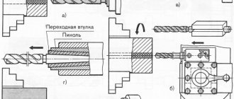
Several types of grooves can be obtained on the surface of the workpiece.
- Narrow grooves, the width of which corresponds to the width of the cutting part of the tool, are made in one pass of the cutter, which is fed manually. Before this, the exact location of the groove is determined on the surface of the part, and then the cutter is placed opposite this place and fed.
- The grooves on the ledges and ends of the part are made according to the same principle; their diameter is set using the transverse feed dial, and their depth is set using the longitudinal movement dial of the caliper.
- Wide grooves are made in several passes according to the following scheme. First, determine the location of the right edge of the groove and place the cutter opposite this location. Using a transverse feed, the cutter is cut into the part to a depth that is 0.5 mm less than the depth of the groove being cut (this allowance is left for finishing). Then, using a longitudinal feed, the groove tool begins to move to the left edge of the groove being cut, the boundary of which has been previously marked. After the rough groove is formed, its bottom is processed cleanly - to the required depth, carrying out the longitudinal feed of the cutter from left to right. In the event that it is necessary to form a groove with a very precise location of its left and right edges, allowances can also be left on them during roughing, which are then removed using the transverse feed of a groove or scoring cutter.
Types of work performed by grooving cutters