| cone in Wiktionary |
This term has other meanings, see Cone (meanings).
Cone
(from ancient Greek κώνος “pine cone”[1]) is a body in Euclidean space obtained by combining all rays emanating from one point (
the vertex
of the cone) and passing through a flat surface.
Sometimes a cone is a part of such a body that has a limited volume and is obtained by combining all the segments connecting the vertex and points of a flat surface (the latter in this case is called the base
of the cone, and the cone is called
resting
on this base). If the base of a cone is a polygon, the cone is a pyramid.
Related definitions
- The segment connecting the top and the boundary of the base is called the generator of the cone
. - The union of the generators of a cone is called the generator
(or
lateral
)
surface of the cone
. The forming surface of the cone is a conical surface. - A segment dropped perpendicularly from the top to the plane of the base (as well as the length of such a segment) is called the height of the cone
. - The opening angle of a cone
is the angle between two opposite generatrices (the angle at the apex of the cone, inside the cone). - If the base of a cone has a center of symmetry (for example, it is a circle or an ellipse) and the orthogonal projection of the vertex of the cone onto the plane of the base coincides with this center, then the cone is called straight
.
In this case, the straight line connecting the top and the center of the base is called the axis of the cone
. - An oblique
(
oblique
) cone is a cone whose orthogonal projection of the vertex onto the base does not coincide with its center of symmetry. - A circular cone
is a cone whose base is a circle. - A right circular cone
(often simply called a cone) can be obtained by rotating a right triangle around a straight line containing a leg (this straight line represents the axis of the cone). - A cone resting on an ellipse, parabola or hyperbola is called an elliptic
,
parabolic
and
hyperbolic cone
(the latter two have infinite volume). - The part of the cone lying between the base and a plane parallel to the base and located between the top and the base is called a truncated cone
, or
conical layer
.
Inclined cone development
Let us consider the procedure for constructing a scan of the lateral surface of an inclined cone using the approximation (approximation) method.
Algorithm
- We inscribe the hexagon 123456 into the circle of the base of the cone. We connect points 1, 2, 3, 4, 5 and 6 with the vertex S. The pyramid S123456, constructed in this way, with a certain degree of approximation is a replacement for the conical surface and is used as such in further constructions.
- We determine the natural values of the edges of the pyramid using the method of rotation around the projecting straight line: in the example, the i axis is used, perpendicular to the horizontal projection plane and passing through the vertex S. Thus, as a result of rotation of the edge S5, its new horizontal projection S'5'1 takes a position at which it is parallel to the frontal plane π2. Accordingly, S''5''1 is the natural value of S5.
- We construct a development of the lateral surface of the pyramid S123456, consisting of six triangles: S01060, S06050, S05040, S04030, S03020, S02010. The construction of each triangle is carried out on three sides. For example, △S01060 has length S010=S''1''0, S060=S''6''1, 1060=1'6'.
The degree to which the approximate development corresponds to the actual one depends on the number of faces of the inscribed pyramid. The number of faces is chosen based on the ease of reading the drawing, the requirements for its accuracy, the presence of characteristic points and lines that need to be transferred to the development.
Transferring a line from the surface of a cone to a development
Line n lying on the surface of the cone is formed as a result of its intersection with a certain plane (figure below). Let's consider the algorithm for constructing line n on a scan.
Algorithm
- We find the projections of points A, B and C at which line n intersects the edges of the pyramid S123456 inscribed in the cone.
- We determine the natural size of the segments SA, SB, SC by rotating around the projecting straight line. In the example under consideration, SA=S''A'', SB=S''B''1, SC=S''C''1.
- We find the position of points A0, B0, C0 on the corresponding edges of the pyramid, plotting on the scan the segments S0A0=S''A'', S0B0=S''B''1, S0C0=S''C''1.
- We connect points A0, B0, C0 with a smooth line.
Properties
- If the area of the base is finite, then the volume of the cone is also finite and equal to one third of the product of the height and the area of the base.
V={1 \over 3} SH,
where S
- base area,
H
- height. Thus, all cones resting on a given base (of finite area) and having a vertex located on a given plane parallel to the base have equal volume, since their heights are equal.
- The center of gravity of any cone with a finite volume lies at a quarter of the height from the base.
- The solid angle at the vertex of a right circular cone is equal to
2\pi \left(1 - \cos {\alpha \over 2} \right), where α is the opening angle of the cone.
- The lateral surface area of such a cone is equal to
S = \pi R l,
and the total surface area (i.e., the sum of the areas of the lateral surface and base)
S = \pi R (l + R), where
R
is the radius of the base,
l
is the length of the generatrix.
- The volume of a circular cone is equal to
V={1 \over 3} \pi R^2H.
- For a truncated cone (not necessarily straight and circular), the volume is equal to:
V={1 \over 3} (HS_2-hS_1),
where S1 and S2 are the areas of the upper (closest to the top) and lower bases, respectively, h
and
H
are the distances from the plane of the upper and lower base, respectively, to the top.
- The intersection of a plane with a right circular cone is one of the conic sections (in non-degenerate cases - an ellipse, parabola or hyperbola, depending on the position of the cutting plane).
Volume calculation
The formula for the volume of any cone is as follows:
V = 1/3 * π * h * r2
where V is the volume of the cone;
h – height;
r – radius;
π is a constant equal to 3.14.
In order to calculate the volume of a cone, it is necessary to have data on the height and radius of the base of the body.
To calculate the height of a body, you need to know the radius of the base and the length of its generatrix. Since the radius, height and generator are combined into a right triangle, the height can be calculated using the formula from the Pythagorean theorem (a2+ b2= c2 or in our case h2+ r2= l2, where l is the generator). The height will be calculated by taking the square root of the difference between the squares of the hypotenuse and the other leg:
a = √c2- b2
That is, the height of the cone will be equal to the value obtained after taking the square root of the difference between the square of the length of the generatrix and the square of the radius of the base:
h = √l2 - r2
By calculating the height using this method and knowing the radius of its base, you can calculate the volume of the cone. The generator plays an important role in this case, since it serves as an auxiliary element in the calculations.
Similarly, if the height of a body and the length of its generatrice are known, one can find out the radius of its base by taking the square root of the difference between the square of the generatrix and the square of the height:
r = √l2 – h2
Then, using the same formula as above, calculate the volume of the cone.
Cone equation
Equations defining the lateral surface of a right circular cone with an opening angle of 2Θ, a vertex at the origin and an axis coinciding with the Oz
:
- In a spherical coordinate system with coordinates ( r
, φ, θ):
\theta = \Theta.
- In a cylindrical coordinate system with coordinates ( r
, φ,
z
):
z = r\cdot\operatorname{ctg}\Theta or r = z\cdot\operatorname{tg}\Theta.
- In a Cartesian coordinate system with coordinates ( x
,
y
,
z
):
z = \plusmn \sqrt{x^2+y^2}\cdot \operatorname{ctg}\Theta.
This equation in canonical form is written as \frac {x^2} {a^2} + \frac {y^2} {b^2} - \frac {z^2} {c^2} = 0, where the constants a
,
by
the proportion c/a = \cos \Theta/\sin\Theta.
This shows that the lateral surface of a right circular cone is a second-order surface (it is called a conical surface
).
In general, a second-order conical surface rests on an ellipse; in a suitable Cartesian coordinate system (the Ox
and
Oy
are parallel to the axes of the ellipse, the vertex of the cone coincides with the origin, the center of the ellipse lies on the
Oz
), its equation has the form
\frac {x^2} {a^2} + \frac {y^ 2} {b^2} — \frac {z^2} {c^2} = 0,
and a/c
and
b/c
are equal to the semi-axes of the ellipse. In the most general case, when a cone rests on an arbitrary flat surface, it can be shown that the equation of the lateral surface of the cone (with the vertex at the origin) is given by the equation f(x,y,z)=0, where the function f(x,y,z ) is homogeneous, that is, satisfying the condition f(\alpha x,\alpha y,\alpha z)=\alpha^nf(x,y,z) for any real number α.
Cone section
The axial section of a cone is a plane passing along its axis or height. In a right cone, such a section is an isosceles triangle, in which the height of the triangle is the height of the body, its sides are the generators, and the base is the diameter of the base. In an equilateral geometric body, the axial section is an equilateral triangle, since in this cone the diameter of the base and the generators are equal.
The plane of the axial section in a straight cone is the plane of its symmetry. The reason for this is that its top is located above the center of its base, that is, the plane of the axial section divides the cone into two identical parts.
Since the height and axis do not coincide in an inclined volumetric body, the axial section plane may not include the height. If a set of axial sections in such a cone can be constructed, since for this only one condition must be met - it must pass only through the axis, then the axial section of the plane to which the height of this cone will belong can only be drawn, because the number of conditions increases, and, as is known, two straight lines (together) can belong to only one plane.
Scan
A right circular cone as a body of revolution is formed by a right triangle rotating around one of the legs, where h
- the height of the cone from the center of the base to the top - is the leg of the right triangle around which rotation occurs.
The second leg of a right triangle r
is the radius at the base of the cone.
The hypotenuse of a right triangle is l
- the generator of the cone.
r values can be used to create a cone scan
and
l
.
The radius of the base r
determines the circle of the base of the cone in the development, and the sector of the lateral surface of the cone is determined by the generatrix of the lateral surface
l
, which is the radius of the sector of the lateral surface.
The sector angle \varphi in the development of the lateral surface of the cone is determined by the formula: φ = 360°·( r
/
l
).
Straight cone with round base
Perhaps this cone is the most common of the class of figures under consideration. It consists of a circle and a side surface. It is not difficult to obtain it using geometric methods. To do this, take a right triangle and rotate it around an axis that coincides with one of the legs. Obviously, this leg will become the height of the figure, and the length of the second leg of the triangle forms the radius of the base of the cone. The diagram below demonstrates the described scheme for obtaining the rotation figure in question.
The triangle shown can be rotated around another leg, which will result in a cone with a larger base radius and a smaller height than the first.
To unambiguously determine all the parameters of a round straight cone, you should know any two of its linear characteristics. Among them are the radius r, height h or length of the generator g. All these quantities are the lengths of the sides of the right triangle under consideration, therefore the Pythagorean theorem is valid for their connection:
g2 = r2 + h2.
Excerpt characterizing the Cone
Prince Andrei arrived at the apartment of General Bennigsen, who occupied a small landowner's house on the very bank of the river. Neither Bennigsen nor the sovereign were there, but Chernyshev, the sovereign’s aide-de-camp, received Bolkonsky and announced to him that the sovereign had gone with General Bennigsen and the Marquis Paulucci another time that day to tour the fortifications of the Drissa camp, the convenience of which was beginning to be seriously doubted. Chernyshev was sitting with a book of a French novel at the window of the first room. This room was probably formerly a hall; there was still an organ in it, on which some carpets were piled, and in one corner stood the folding bed of Adjutant Bennigsen. This adjutant was here. He, apparently exhausted by a feast or business, sat on a rolled up bed and dozed. Two doors led from the hall: one straight into the former living room, the other to the right into the office. From the first door one could hear voices speaking in German and occasionally in French. There, in the former living room, at the sovereign’s request, not a military council was gathered (the sovereign loved uncertainty), but some people whose opinions on the upcoming difficulties he wanted to know. This was not a military council, but, as it were, a council of those elected to clarify certain issues personally for the sovereign. Invited to this half-council were: the Swedish General Armfeld, Adjutant General Wolzogen, Wintzingerode, whom Napoleon called a fugitive French subject, Michaud, Tol, not a military man at all - Count Stein and, finally, Pfuel himself, who, as Prince Andrei heard, was la cheville ouvriere [the basis] of the whole matter. Prince Andrei had the opportunity to take a good look at him, since Pfuhl arrived soon after him and walked into the living room, stopping for a minute to talk with Chernyshev. At first glance, Pfuel, in his poorly tailored Russian general's uniform, which sat awkwardly on him, as if dressed up, seemed familiar to Prince Andrei, although he had never seen him. It included Weyrother, Mack, Schmidt, and many other German theoretic generals whom Prince Andrei managed to see in 1805; but he was more typical than all of them. Prince Andrei had never seen such a German theoretician, who combined in himself everything that was in those Germans. Pfuel was short, very thin, but broad-boned, of a rough, healthy build, with a wide pelvis and bony shoulder blades. His face was very wrinkled, with deep-set eyes. His hair in front, near his temples, was obviously hastily smoothed with a brush, and naively stuck out with tassels at the back. He, looking around restlessly and angrily, entered the room, as if he was afraid of everything in the large room into which he entered. He, holding his sword with an awkward movement, turned to Chernyshev, asking in German where the sovereign was. He apparently wanted to go through the rooms as quickly as possible, finish bowing and greetings, and sit down to work in front of the map, where he felt at home. He hastily nodded his head at Chernyshev’s words and smiled ironically, listening to his words that the sovereign was inspecting the fortifications that he, Pfuel himself, had laid down according to his theory. He grumbled something deep and coolly, as self-confident Germans say, to himself: Dummkopf... or: zu Grunde die ganze Geschichte... or: s'wird was gescheites d'raus werden... [nonsense... to hell with the whole thing... (German) ] Prince Andrei did not hear and wanted to pass, but Chernyshev introduced Prince Andrei to Pful, noting that Prince Andrei came from Turkey, where the war was so happily over. Pful almost looked not so much at Prince Andrei as through him, and said laughing: “Da muss ein schoner taktischcr Krieg gewesen sein.” [“It must have been a correctly tactical war.” (German)] - And, laughing contemptuously, he walked into the room from which voices were heard. Apparently, Pfuel, who was always ready for ironic irritation, was now especially excited by the fact that they dared to inspect his camp without him and judge him. Prince Andrei, from this one short meeting with Pfuel, thanks to his Austerlitz memories, compiled a clear description of this man. Pfuel was one of those hopelessly, invariably, self-confident people to the point of martyrdom, which only Germans can be, and precisely because only Germans are self-confident on the basis of an abstract idea - science, that is, an imaginary knowledge of perfect truth. The Frenchman is self-confident because he considers himself personally, both in mind and body, to be irresistibly charming to both men and women. An Englishman is self-confident on the grounds that he is a citizen of the most comfortable state in the world, and therefore, as an Englishman, he always knows what he needs to do, and knows that everything he does as an Englishman is undoubtedly good. The Italian is self-confident because he is excited and easily forgets himself and others. The Russian is self-confident precisely because he knows nothing and does not want to know, because he does not believe that it is possible to completely know anything. The German is the worst self-confident of all, and the firmest of all, and the most disgusting of all, because he imagines that he knows the truth, a science that he himself invented, but which for him is the absolute truth. This, obviously, was Pfuel. He had a science - the theory of physical movement, which he derived from the history of the wars of Frederick the Great, and everything that he encountered in the modern history of the wars of Frederick the Great, and everything that he encountered in the latest military history, seemed to him nonsense, barbarism, an ugly clash, in which so many mistakes were made on both sides that these wars could not be called wars: they did not fit the theory and could not serve as the subject of science. In 1806, Pfuel was one of the drafters of the plan for the war that ended with Jena and Auerstätt; but in the outcome of this war he did not see the slightest proof of the incorrectness of his theory. On the contrary, the deviations made from his theory, according to his concepts, were the only reason for the entire failure, and he, with his characteristic joyful irony, said: “Ich sagte ja, daji die ganze Geschichte zum Teufel gehen wird.” [After all, I said that the whole thing would go to hell (German)] Pfuel was one of those theorists who love their theory so much that they forget the purpose of theory - its application to practice; In his love for theory, he hated all practice and did not want to know it. He even rejoiced at failure, because failure, which resulted from a deviation in practice from theory, only proved to him the validity of his theory. He said a few words with Prince Andrei and Chernyshev about the real war with the expression of a man who knows in advance that everything will be bad and that he is not even dissatisfied with it. The unkempt tufts of hair sticking out at the back of his head and the hastily slicked temples especially eloquently confirmed this. He walked into another room, and from there the bassy and grumbling sounds of his voice were immediately heard. Before Prince Andrei had time to follow Pfuel with his eyes, Count Bennigsen hurriedly entered the room and, nodding his head to Bolkonsky, without stopping, walked into the office, giving some orders to his adjutant. The Emperor was following him, and Bennigsen hurried forward to prepare something and have time to meet the Emperor. Chernyshev and Prince Andrey went out onto the porch. The Emperor got off his horse with a tired look. Marquis Paulucci said something to the sovereign. The Emperor, bowing his head to the left, listened with a dissatisfied look to Paulucci, who spoke with particular fervor. The Emperor moved forward, apparently wanting to end the conversation, but the flushed, excited Italian, forgetting decency, followed him, continuing to say:
How to calculate the angle of a cone
Content
| Cone elements | Calculation formulas | Cone elements | Calculation formulas |
| K | K = (Dd)/ l K = 2tga | D | D = K× l + d D = 2× l×tga + d |
| a | tga = (Dd)/ 2l tga = K / 2 | d | d = D – 2× l×tga d = D – K× l |
Angle a is calculated using the trigonometric tangent function.
Normal conical surfaces must be made to standard dimensions, some of which are listed in Table 4.
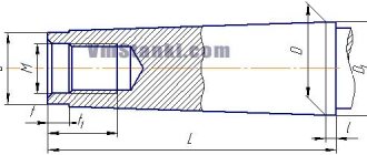
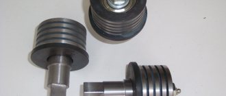
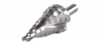
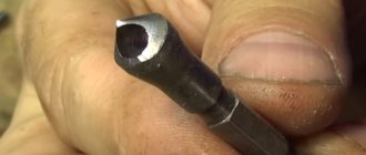
In addition to these surfaces, there are also Morse cones and metric cones. External Morse cones are made on the tail part of the drills (see Fig
), countersinks, reamers, centers, and internal cones - in the holes of spindles, mandrels, adapter bushings into which these tools are installed.
There are seven numbers of Morse cones (from to 6
) with their own sizes and angles of inclination
a
.
The smallest is the Morse cone ( 1:19.212
), the largest is the Morse cone
6
(
1:19.18
).
Their dimensions are given in the ST SEV 147-75 standard. The disadvantage of Morse cones is the different angles of inclination a
for different numbers.
Table 4
Standard sizes of part cones
| Taper K | Cone angle 2a | Tilt angle a | Taper designation |
| 1:100 1:50 1:20 1:10 1:3 1:1,866 1:1,207 1:0,866 | 0 0 34¢23² 1 0 8¢45² 2 0 51¢51² 5 0 43¢29² 18 0 55¢30² 30 0 45 0 60 0 | 0 0 17¢12² 0 0 34¢23² 1 0 25¢56² 2 0 51¢45² 9 0 27¢45² 15 0 22 0 30¢ 30 0 | 1:100 1:50 1:20 1:10 1:3 30 0 45 0 60 0 |
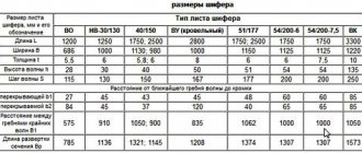
Metric cones 4, 6, 80, 100, 120, 160, 200
(see the same standard) have the same taper of
1:20
(and angle
a
), and the taper number indicates the diameter size of the large base.
Didn't find what you were looking for? Use the search:
Best sayings:
What kind of mathematicians are you if you can’t password protect properly.
8256 – | 7223 – or read all.
91.146.8.87 © studopedia.ru Not the author of the materials posted. But it provides free use. Is there a copyright violation? Write to us | Feedback.
Disable adBlock! and refresh the page (F5)
very necessary
Taper is the ratio of the difference in diameters of two cross sections of a circular cone to the distance between them.
The taper has a double Slope: k=2i The taper in the drawing can be indicated in degrees, in radians and as a percentage. The taper is set to 1:5, diameter D=BC=20 mm, length l=35 mm.
It is necessary to construct the outline of the faucet plug in one of two ways: The first method. From the formula k=2i we find i=1:10. Mark points BC and construct triangle DKP so that KP:BK=1:10. Continuing BP until it intersects with the axis of the cone, we obtain the vertex of the cone S. We connect point S to point C. Setting aside a segment l=35 mm along the axis of the plug from BC and drawing a straight line through the end of this segment, perpendicular to the axis, we obtain the diameter d=EF=13 mm of the end of the plug; Second way. From the formula k=(Dd)/l we find d=EF=20-35/5=13 mm; Angle at the apex of the cone:
here the angle φ is represented in radians.
where L is the distance from the large section to the top S of the cone, and the ratio: D/(2L) = tgφ Let the taper , for example 1: 2.5, from which i=1:5 and tgφ=0.2 then its conversion to degrees is carried out according formulas:
The taper is standardized. GOST 8593-81 establishes normal tapers and cone angles
| Designation | cone | Cone- | ness | Corner | cone | Corner | slope |
| Row 1 | Row 2 | Angle units | Glad. | Angle units | Glad. | ||
| 1:500 | 1:500 | 0,0020000 | 6`52,5″ | 0,0020000 | 3`26,25″ | 0,0010000 | |
| 1:200 | 1:200 | 0,0050000 | 17`11,3″ | 0,0050000 | 8`25,65″ | 0,0025000 | |
| 1:100 | 1:100 | 0,0100000 | 34`22,6″ | 0,0100000 | 17`11,3″ | 0,0050000 | |
| 1:50 | 1:50 | 0,0200000 | 1°8`45,2″ | 0,0199996 | 34`22,6″ | 0,0099998 | |
| 1:30 | 1:30 | 0,0333333 | 1°54`34,9″ | 0,0333304 | 57`17,45″ | 0,0166652 | |
| 1:20 | 1:20 | 0,0500000 | 2°51`51,1″ | 0,0499896 | 1°25`55,55″ | 0,0249948 | |
| 1:15 | 1:15 | 0,0666667 | 3°49`5,9″ | 0,0666420 | 1°54`32,95″ | 0,0333210 | |
| 1:12 | 1:12 | 0,0833333 | 4°46`18,8″ | 0,0832852 | 2°23`9,4″ | 0,0416426 | |
| 1:10 | 1:10 | 0,1000000 | 5°43`29,3″ | 0,0999168 | 2°51`44,65″ | 0,0499584 | |
| 1:8 | 1:8 | 0,1250000 | 7°9`9,6″ | 0,1248376 | 3°34`34,8″ | 0,0624188 | |
| 1:7 | 1:7 | 0,1428571 | 8°10`16,4″ | 0,1426148 | 4°5`8,2″ | 0,0713074 | |
| 1:6 | 1:6 | 0,1666667 | 9°31`38,2″ | 0,1662824 | 4°45`49,1″ | 0,0831412 | |
| 1:5 | 1:5 | 0,2000000 | 11°25`16,3″ | 0,1993374 | 5°42`38,15″ | 0,0996687 | |
| 1:4 | 1:4 | 0,2500000 | 14°15`0,1″ | 0,2487100 | 7°7`30,05″ | 0,1243550 | |
| 1:3 | 1:3 | 0,3333333 | 18°55`28,7″ | 0,3302972 | 9°27`44,35″ | 0,1651486 | |
| 30° | 1:1,866025 | 0,5358985 | 30° | 0,5235988 | 15° | 0,2617994 | |
| 45° | 1:1,207107 | 0,8284269 | 45° | 0,7853982 | 22°30` | 0,3926991 | |
| 60° | 1:0,866025 | 1,1547010 | 60° | 1,0471976 | 30° | 0,5235988 | |
| 75° | 1:0,651613 | 1,5346532 | 75° | 1,3089970 | 37°30` | 0,6544985 | |
| 90° | 1:0,500000 | 2,0000000 | 90° | 1,5707964 | 45° | 0,7853982 | |
| 120° | 1:0,288675 | 3,4641032 | 120° | 2,0943952 | 60° | 1,0471976 |
The tapers and angles of the cones must correspond to those indicated in the drawing and table. When selecting tapers or taper angles, Row 1 should be preferred to Row 2.
Surface taper
indicated on the drawing: – by the inscription Taper indicating its value; – an arrow pointing at it with a shelf where it is written: – Taper with an indication of its value; – sign of the taper and its magnitude.
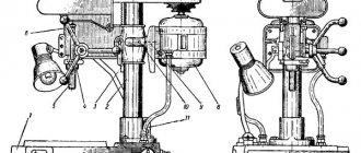
In mechanical engineering, along with cylindrical ones, parts with conical surfaces in the form of external cones or in the form of conical holes are widely used. For example, the center of a lathe has two outer cones, one of which serves to install and secure it in the conical hole of the spindle; a drill, countersink, reamer, etc. also have an outer cone for installation and fastening. The adapter sleeve for fastening drills with a conical shank has an outer cone and a conical hole
Read also: Device for measuring metal hardness
The concept of a cone and its elements
Elements of a cone. If you rotate the right triangle ABC around the leg AB (Fig. 202, a), then a body ABG is formed, called a full cone
.
Line AB is called the axis or altitude of the cone
, line AB is called
the generator of the cone
.
Point A is the vertex of the cone
.
When the leg BV rotates around the axis AB, a circle surface is formed, called the base of the cone
.
The angle VAG between the lateral sides AB and AG is called the cone angle
and is denoted by 2α.
Half of this angle formed by the lateral side AG and the axis AB is called the cone angle
and is denoted α. Angles are expressed in degrees, minutes and seconds.
If we cut off its upper part from a complete cone with a plane parallel to its base (Fig. 202, b), we obtain a body called a truncated cone
.
It has two bases, upper and lower. The distance OO1 along the axis between the bases is called the height of the truncated cone
. Since in mechanical engineering we mostly have to deal with parts of cones, i.e. truncated cones, they are usually simply called cones; From now on we will call all conical surfaces cones.
The connection between the elements of the cone. The drawing usually indicates three main dimensions of the cone: the larger diameter D, the smaller diameter d and the height of the cone l (Fig. 203).
Sometimes the drawing indicates only one of the cone diameters, for example, the larger D, the cone height l and the so-called taper. Taper is the ratio of the difference between the diameters of a cone and its length. Let us denote the taper by the letter K, then
If the cone has dimensions: D = 80 mm, d = 70 mm and l = 100 mm, then according to formula (10):
This means that over a length of 10 mm the diameter of the cone decreases by 1 mm or for every millimeter of the length of the cone the difference between its diameters changes by
Sometimes on the drawing, instead of the angle of the cone, the slope of the cone
. The slope of the cone shows the extent to which the generatrix of the cone deviates from its axis. The slope of the cone is determined by the formula
where tan α is the slope of the cone; D is the diameter of the large base of the cone in mm; d is the diameter of the small base of the cone in mm; l is the height of the cone in mm.
Using formula (11), you can use trigonometric tables to determine the angle a of the cone.
Cone slope and taper are usually expressed as a simple fraction, for example: 1: 10; 1:50, or a decimal fraction, for example, 0.1; 0.05; 0.02, etc.
Methods for producing conical surfaces on a lathe
On a lathe, processing of conical surfaces is carried out in one of the following ways: a) turning the upper part of the support; b) transverse displacement of the tailstock body; c) using a cone ruler; d) using a wide cutter.
Machining conical surfaces by turning the upper part of the caliper
When making short external and internal conical surfaces with a large slope angle on a lathe, you need to rotate the upper part of the support relative to the axis of the machine at an angle α of the cone slope (see Fig. 204). With this method of operation, feeding can only be done by hand, rotating the handle of the lead screw of the upper part of the support, and only the most modern lathes have a mechanical feed of the upper part of the support.
To set the upper part of the caliper 1 to the required angle, you can use the divisions marked on the flange 2 of the rotating part of the caliper (Fig. 204). If the slope angle α of the cone is specified according to the drawing, then the upper part of the caliper is rotated together with its rotating part by the required number of divisions indicating degrees. The number of divisions is counted relative to the mark marked on the bottom of the caliper.
If the angle α is not given in the drawing, but the larger and smaller diameters of the cone and the length of its conical part are indicated, then the value of the caliper rotation angle is determined by formula (11)
The method of turning conical surfaces by turning the upper part of the caliper has the following disadvantages: it usually allows the use of only manual feed, which affects labor productivity and the cleanliness of the machined surface; allows you to grind relatively short conical surfaces limited by the stroke length of the upper part of the caliper.
Machining of conical surfaces using the method of transverse displacement of the tailstock housing
To obtain a conical surface on a lathe, when rotating the workpiece, it is necessary to move the tip of the cutter not parallel, but at a certain angle to the axis of the centers. This angle must be equal to the slope angle α of the cone. The simplest way to obtain the angle between the axis of the centers and the direction of feed is to shift the line of centers by moving the back center in the transverse direction. By shifting the rear center towards the cutter (toward itself) as a result of grinding, a cone is obtained, the larger base of which is directed towards the headstock; when the rear center is shifted in the opposite direction, i.e., away from the cutter (away from you), the larger base of the cone will be on the side of the tailstock (Fig. 205).
The displacement of the tailstock body is determined by the formula
where S is the displacement of the tailstock body from the axis of the headstock spindle in mm; D is the diameter of the large base of the cone in mm; d is the diameter of the small base of the cone in mm; L is the length of the entire part or the distance between centers in mm; l is the length of the conical part of the part in mm.
The tailstock housing is shifted using divisions 1 (Fig. 206) marked on the end of the base plate, and mark 2 on the end of the tailstock housing.
If there are no divisions at the end of the plate, then move the tailstock body using a measuring ruler, as shown in Fig. 207.
Read also: Nikolay Matveev Vologda author
The advantage of machining conical surfaces by displacing the tailstock body is that this method can be used to turn long cones and grind with mechanical feed.
Disadvantages of this method: inability to bore conical holes; loss of time for rearranging the tailstock; the ability to process only shallow cones; misalignment of the centers in the center holes, which leads to rapid and uneven wear of the centers and center holes and causes defects during the secondary installation of the part in the same center holes.
Uneven wear of the center holes can be avoided if a special ball center is used instead of the usual one (Fig. 208). Such centers are mainly used when processing precision cones.
Machining conical surfaces using a conical ruler
For machining conical surfaces with a slope angle of up to 10-12°, modern lathes usually have a special device called a cone ruler. The scheme for processing a cone using a cone ruler is shown in Fig. 209.
A plate 11 is attached to the machine bed, on which a conical ruler 9 is mounted. The ruler can be rotated around pin 8 at the required angle a to the axis of the workpiece. To secure the ruler in the required position, two bolts 4 and 10 are used. A slider 7 slides freely along the ruler, connecting to the lower transverse part 12 of the caliper using a rod 5 and a clamp 6. So that this part of the caliper can slide freely along the guides, it is disconnected from the carriage 3 by unscrewing the cross screw or disconnecting its nut from the caliper.
If you give the carriage a longitudinal feed, then the slider 7, captured by the rod 5, will begin to move along the ruler 9. Since the slider is attached to the transverse slide of the caliper, they, together with the cutter, will move parallel to the ruler 9. Thanks to this, the cutter will process a conical surface with an inclination angle , equal to the angle α of rotation of the conical ruler.
After each pass, the cutter is set to the cutting depth using the handle 1 of the upper part 2 of the caliper. This part of the caliper must be rotated 90° relative to the normal position, i.e., as shown in Fig. 209.
If the diameters of the bases of the cone D and d and its length l are given, then the angle of rotation of the ruler can be found using formula (11).
Having calculated the value of tan α, it is easy to determine the value of angle α using the table of tangents. The use of a cone ruler has a number of advantages: 1) setting up the ruler is convenient and quick; 2) when switching to processing cones, there is no need to disrupt the normal setup of the machine, i.e., there is no need to move the tailstock body; the centers of the machine remain in the normal position, i.e. on the same axis, due to which the center holes in the part and the centers of the machine do not work; 3) using a conical ruler, you can not only grind the outer conical surfaces, but also bore conical holes; 4) it is possible to work with a longitudinal self-propelled machine, which increases labor productivity and improves the quality of processing.
The disadvantage of a tapered ruler is the need to disconnect the caliper slide from the cross feed screw. This drawback is eliminated in the design of some lathes, in which the screw is not rigidly connected to its handwheel and the gear wheels of the transverse self-propelled machine.
Machining conical surfaces with a wide cutter
Machining of conical surfaces (external and internal) with a short cone length can be done with a wide cutter with a plan angle corresponding to the slope angle α of the cone (Fig. 210). The cutter feed can be longitudinal or transverse.
However, the use of a wide cutter on conventional machines is only possible with a cone length not exceeding approximately 20 mm. Wider cutters can only be used on particularly rigid machines and parts if this does not cause vibration of the cutter and the workpiece.
Boring and reaming of tapered holes
Machining tapered holes is one of the most difficult turning jobs; it is much more difficult than processing external cones.
The machining of conical holes on lathes is in most cases carried out by boring with a cutter with turning the upper part of the support and, less often, using a tapered ruler. All calculations associated with turning the upper part of the caliper or the tapered ruler are performed in the same way as when turning the outer conical surfaces.
If the hole must be in solid material, then first a cylindrical hole is drilled, which is then bored into a cone with a cutter or machined with conical countersinks and reamers.
To speed up boring or reaming, you should first drill a hole with a drill, diameter d, which is 1-2 mm less than the diameter of the small base of the cone (Fig. 211, a). After this, the hole is drilled with one (Fig. 211, b) or two (Fig. 211, c) drills to obtain steps.
After finishing boring the cone, it is reamed using a conical reamer of the appropriate taper. For cones with a small taper, it is more profitable to process the conical holes immediately after drilling with a set of special reamers, as shown in Fig. 212.
Cutting modes when processing holes with conical reamers
Conical reamers work under more difficult conditions than cylindrical reamers: while cylindrical reamers remove a slight allowance with small cutting edges, conical reamers cut the entire length of their cutting edges located on the generatrix of the cone. Therefore, when working with conical reamers, feeds and cutting speeds are used less than when working with cylindrical reamers.
When processing holes with conical reamers, the feed is done manually by rotating the tailstock handwheel. It is necessary to ensure that the tailstock quill moves evenly.
Feed when reaming steel is 0.1-0.2 mm/rev, when reaming cast iron 0.2-0.4 mm/rev.
The cutting speed when reaming conical holes with high-speed steel reamers is 6-10 m/min.
Read also: Canopies over the gate photo
Cooling should be used to facilitate the operation of conical reamers and to obtain a clean, smooth surface. When processing steel and cast iron, an emulsion or sulfofresol is used.
Measuring conical surfaces
The surfaces of the cones are checked with templates and gauges; measuring and simultaneously checking the angles of the cone is carried out using protractors. In Fig. 213 shows a method for checking a cone using a template.
The outer and inner corners of various parts can be measured with a universal goniometer (Fig. 214). It consists of a base 1, on which the main scale is marked on an arc 130. A ruler 5 is rigidly attached to the base 1. Sector 4 moves along the arc of the base, carrying a vernier 3. A square 2 can be attached to the sector 4 by means of a holder 7, in which, in turn, a removable ruler 5 is fixed. The square 2 and the removable ruler 5 have ability to move along the edge of sector 4.
Through various combinations in the installation of the measuring parts of the protractor, it is possible to measure angles from 0 to 320°. The reading value on the vernier is 2′. The reading obtained when measuring angles is made using the scale and vernier (Fig. 215) as follows: the zero stroke of the vernier indicates the number of degrees, and the vernier stroke, which coincides with the stroke of the base scale, indicates the number of minutes. In Fig. 215 the 11th stroke of the vernier coincides with the stroke of the base scale, which means 2'X 11 = 22'. Therefore, the angle in this case is 76°22′.
In Fig. 216 shows combinations of measuring parts of a universal protractor, allowing the measurement of various angles from 0 to 320°.
For more accurate testing of cones in mass production, special gauges are used. In Fig. 217, and shows a conical bushing gauge for checking outer cones, and in Fig. 217, b—conical plug gauge for checking conical holes.
On the gauges, ledges 1 and 2 are made at the ends or marks 3 are applied, which serve to determine the accuracy of the surfaces being checked.
On the. rice. 218 provides an example of checking a conical hole with a plug gauge.
To check the hole, a gauge (see Fig. 218), which has a ledge 1 at a certain distance from the end 2 and two marks 3, is inserted with light pressure into the hole and checked to see if the gauge is swinging in the hole. No wobble indicates that the cone angle is correct. Once you are sure that the angle of the cone is correct, proceed to check its size. To do this, observe to what point the gauge will enter the part being tested. If the end of the part's cone coincides with the left end of ledge 1 or with one of the marks 3 or is between the marks, then the dimensions of the cone are correct. But it may happen that the gauge enters the part so deeply that both marks 3 enter the hole or both ends of the ledge 1 come out of it. This indicates that the hole diameter is larger than specified. If, on the contrary, both risks are outside the hole or none of the ends of the ledge come out of it, then the diameter of the hole is less than the required one.
To accurately check the taper, use the following method. On the surface of the part or gauge to be measured, draw two or three lines with chalk or a pencil along the generatrix of the cone, then insert or put the gauge on the part and turn it part of the turn. If the lines are erased unevenly, this means that the cone of the part is not processed accurately and needs to be corrected. The erasing of lines at the ends of the gauge indicates an incorrect taper; the erasing of the lines in the middle part of the caliber shows that the taper has a slight concavity, which is usually caused by the inaccurate location of the tip of the cutter along the height of the centers. Instead of chalk lines, you can apply a thin layer of special paint (blue) to the entire conical surface of the part or gauge. This method gives greater measurement accuracy.
Defects in the processing of conical surfaces and measures to prevent them
When processing conical surfaces, in addition to the mentioned types of defects for cylindrical surfaces, the following types of defects are additionally possible: 1) incorrect taper; 2) deviations in the dimensions of the cone; 3) deviations in the diameters of the bases with the correct taper; 4) non-straightness of the generatrix of the conical surface.
1. Incorrect taper is mainly due to inaccurate tailstock housing misalignment, inaccurate rotation of the upper part of the caliper, incorrect installation of the taper ruler, incorrect sharpening or installation of the wide cutter. Therefore, by accurately positioning the tailstock housing, the upper part of the caliper or the cone ruler before starting processing, defects can be prevented. This type of defect can be corrected only if the error along the entire length of the cone is directed into the body of the part, that is, all the diameters of the bushing are smaller, and those of the conical rod are larger than required.
2. The wrong size of the cone at the correct angle, i.e., the wrong size of the diameters along the entire length of the cone, occurs if not enough or too much material is removed. Defects can be prevented only by carefully setting the cutting depth along the dial on finishing passes. We will correct the defect if not enough material was filmed.
3. It may turn out that with the correct taper and exact dimensions of one end of the cone, the diameter of the second end is incorrect. The only reason is failure to comply with the required length of the entire conical section of the part. We will correct the defect if the part is too long. To avoid this type of defect, it is necessary to carefully check its length before processing the cone.
4. Non-straightness of the generatrix of the cone being processed is obtained when the cutter is installed above (Fig. 219, b) or below (Fig. 219, c) the center (in these figures, for greater clarity, the distortions of the generatrix of the cone are shown in a greatly exaggerated form). Thus, this type of defect is the result of the inattentive work of the turner.