Technological process of machining
- consistent change in the shape, size and properties of a material or semi-finished product to obtain a part with the required technical conditions.
The technical process has a certain structure and consists of the following elements: Operation
- part of the technological process, performed at one workplace and including all the actions of the worker and the machine for processing workpieces. It is called by the type of equipment on which it is performed (for example, turning, drilling, etc.).
Installation
- part of the operation that is performed with one workpiece secured.
Position
- this is each individual position of the workpiece occupied by it relative to the machine with constant fastening.
Transition
- part of a technological operation performed without changing the cutting tool, the surface being processed, or the processing mode.
Main types and methods of metal machining
Below we list procedures that contribute to changes in physical or chemical qualities and deformation of an object. Before choosing the appropriate method, it is necessary to compare all the characteristics of the metal sample and the result to be obtained. The main goal is to overcome the limit of elastic deformation, that is, it is necessary to ensure that the element changes shape and does not return to its original form.
Milling work
Rotating cutters on the machine are designed for shaped cutting of round workpieces. They are clamped between two spindles, and in rare cases they are screwed to one side. There are manually driven devices, in which case the operator manually guides the tool with the blade, and there are those that are connected to a CNC control panel, that is, they have computerized control. They work in automatic mode, the worker only sets the program and observes the process.
Gear cutting work
This is the procedure of cutting and finishing teeth, such as in the manufacture of gears. The chips are removed in a thin layer using a special machine. First, rough mechanical metalworking occurs, then finishing. Sometimes hardening requires heat treatment followed by grinding and adjustment. The tool is a disk cutter with a profile corresponding to the distance between the teeth.
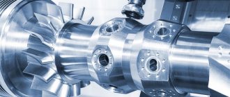
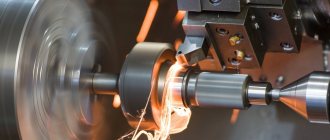
Turning works
Using cutters, drills and reamers, excess chips are removed from the surface metal layer. The desired pattern, depressions, and holes are formed. There are two movements - rotation of the workpiece and the impact of the feed. On a lathe you can drill and ream openings, countersink them, cut threads, cut off a part, and turn grooves. The resulting products will be:
- nuts;
- bushings;
- shafts;
- pulleys;
- couplings;
- rings;
- gear wheels.
Pressure processing equipment
Blacksmithing can be done by hand using a hammer and anvil. The mechanical method involves using a press lowered onto a heated metal surface.
Both devices are mechanical. But the hammer delivers blows, due to which the surface being treated takes on the desired shape, and the press applies pressure.
The hammer can be of the following types:
- steam;
- steam-air;
- falling;
- springy.
Hammer
There are also several types of pressing devices:
Press diagram
- hydraulic;
- steam-hydraulic;
- screw;
- friction;
- eccentric;
- crank;
- spring.
Before pressure treatment begins, the metal surface is heated. However, in recent years, instead of hot impact, cold impact, called stamping, is more often used. Stamping is suitable for working with any type of metal. It allows you to give the product the desired shape without affecting the physical characteristics of the material.
The most popular types of stamping include:
- flexible;
- pulling;
- compression;
- molding;
- bulging;
- beading.
Metal stamping
Bending is used to change the axial shape of a metal element and is done using a vice mounted on bending dies and presses. Drawing is done on a pressing machine and is used to create complex products. By crimping, the cross-section of a part having a cavity is reduced. Molding is used to create elements of spatial forms. To perform these works, special molding dies are used.
By bulging, the workpieces acquire a spatial shape. And beading is used to create sides and other additional elements.
Mechanical processing of metal: types and methods
There are two large categories - with and without removing the top layer. The former include turning, drilling, grinding, crushing and everything that can be classified as cutting. In this case, the shape and dimensions of the workpiece change.
If you do not need to use anything to form a cut, then apply pressure or impact. The impact can be exerted by a press, water, air, or a stream of abrasive particles. The procedure can be carried out together with heat treatment or in natural temperature conditions. This category includes: stamping, pressing, rolled metal.
Chemical treatment
Chemicals facilitate reactions that allow:
- clean the surface from corrosion and contamination;
- apply an additional protective layer - galvanizing, galvanizing;
- increase resistance to external influences.
Typically, ozonation, chrome plating, galvanizing, boriding and application of a composition with aluminum are used.
What does the process of mechanical surface treatment of metals depend on?
You cannot start work right away; you must first create a detailed drawing with dimensions. Then you can choose one of the options or a combination of them, for example, first cut off the excess and then grind it. Sometimes graphic documents are also required for intermediate stages, if there are many of them or they must have a high accuracy class. The choice generally depends on:
- material and its physical and chemical properties;
- sizes;
- the desired shape;
- procedures;
- roughness.
Calculation of mechanical treatment modes for coatings
The main elements of the cutting mode include: depth of cut – t
(mm);
feed S
(mm/rev);
cutting speed V
(m/min) (when turning);
linear speed of the wheel Vк
(m/s) (during grinding);
linear speed of the workpiece Vd
(m/min) (for cylindrical grinding).
The initial data for selecting the cutting mode are: data on the workpiece (working drawing and technical specifications); type of surfacing and coating material, allowance for machining; processing accuracy; required surface roughness after processing, etc.
Selecting cutting mode for turning (turning)
Selection of cutting modes when turning a part with diameter D
is performed in the following sequence:
Depth of cut t
assigned from the ranges:
t
= (0.40–0.80) mm – passage during rough turning;
t
= (0.10–0.30) mm – passage during finishing turning.
Number of passes
calculated by formula (1):
i
=
z
/
t
. (1)
where z
– allowance for turning (per side), mm.
Feed rate for rough turning
selected (for educational purposes) according to Table 7 for turning, taking into account the diameter of the workpiece
D
, and according to Table 8 for boring, taking into account the cross-section of the holder and the overhang of the cutter.
Table 7.
Feed rate when turning steel parts
| Depth of cut t, mm | Part diameter D , mm | |||||||
| Before 18 | 18–30 | 30–50 | 50–80 | 80–120 | 120–180 | 180–260 | St. 260 | |
| Feed S, mm/rev | ||||||||
| Up to 5 | up to 0.25 | 0,2-0.5 | 0,4-0,8 | 0,6-1,0 | 1,0-1,2 | 1,2-1,4 | 14–1,5 | 1,5-1,6 |
Table 8.
Feed rate when boring
| Depth of cut | Circular diameter of the cutter holder, mm | |||||
| To 10 | 10-15 | 15–20 | 20–25 | 25–30 | 30–40 | |
| Cutter overhang, mm | ||||||
| 50 | 80 | 100 | 125 | 150 | 200 | |
| Feed S, mm/rev | ||||||
| Steel t=2 | 0,05-0,08 | 0,08-0,20 | 0,15-0,40 | 0,25-0,70 | 0,50-1,0 | — |
| t=3 | — | 0,08-0,12 | 0,10-0,25 | 0,15-0,40 | 0,20-0,50 | 0,25-0,60 |
| Cast iron t=2 | 0,08-0,12 | 0,25-0,40 | 0,50-0,80 | 0,90-1,50 | — | — |
| t=3 | 0,05-0,08 | 0,15-0,25 | 0,30-0,50 | 0,50-0,90 | 0,90-1,20 | — |
Finish turning feed
is selected based on the required roughness of the machined surface, taking into account the radius at the tip of the cutter
r
(Table 9).
Table 9. Feed depending on the specified surface roughness for a turning cutter with the values of the main and auxiliary angles in the plan φ = φ1 =
45°
| Cutting speed range, m/min | Roughness surfaces, Ra µm | Cutter tip radius r , mm | |||||
| 0,5 | 1,0 | 1,5 | 2,0 | 3,0 | 4,0 | ||
| Innings S , mm/rev | |||||||
| Whole range | 80-40 | — | — | — | — | 2,80 | 3,2 |
| 40-20 | — | — | 1,45 | 1,60 | 1,90 | 2,10 | |
| 20-10 | 0,46 | 0,58-0,89 | 0,67-1,05 | 0,73-1,15 | 0,85-1,30 | 0,93-1,45 | |
| 10-5,0 | 0,20-0,35 | 0,25-0,44 | 0,29-0,51 | 0,32-0,57 | 0,37-0,65 | 0,41-0,71 | |
| 5,0-2,5 | 0,13 | 0,12-0,17 | 0,14-0,20 | 0,16-0,22 | 0,13-0,26 | 0,15-0,30 | |
Cutting speed V
calculated by formula (2):
, m/min, (2)
where t
– cutting depth, mm;
S
– feed, mm/rev;
T
– tool life, min (selected according to table 10)
Table 10. Tool life
| Cutter material | Cutter section in mm | ||||
| 16×25 | 20×30 | 25×40 | 40×60 | 60×90 | |
| Cutter life T (min) | |||||
| High speed steel | 40 | 60 | 90 | 120 | 150 |
| Hard alloy | 50 | 70 | 100 | 150 | 180 |
C value
selected according to table 11.
Table 11. C value
| Processed material | C |
| Steel, steel casting | 47,5 |
| Gray cast iron and copper alloys | 24,0 |
Coefficient value m
selected according to table 12.
Table 12. m value
| Processed material | Types of cutters | Processing conditions | m | ||
| high speed steel | TK alloy | VK alloy | |||
| Steel, steel casting, ductile iron | Passing | With cooling | 0,100 | 0,110 | 0,150 |
| Scoring Boring | No cooling | 0,125 | 0,125 | 0,150 | |
| Cut-off | No cooling | 0,200 | — | 0,150 | |
| Gray cast iron | Pass-through Scoring | No cooling | 0,100 | 0,125 | 0,200 |
| Boring Cutting | No cooling | 0,150 | — | 0,200 | |
The value of the exponent x
: when processing steel –
x
= 0.21, when processing cast iron –
x
= 0.18.
The value of the exponent y
: when processing steel -
y
= 0.27, when processing cast iron -
y
= 0.30.
Part rotation speed n
(rpm) is calculated using formula (3):
, rpm (3)
Basic (technological) time
during turning
To
is calculated using formula (4):
, min, (4)
Where –
estimated processing length in the feed direction, mm;
l
– length of the processed surface, mm;
l
1 – tool penetration length, mm (calculated using formulas in accordance with the geometry of the tool and depth of cut; when turning
l
1 =
t
·
ctg φ
; when calculating the main angle
φ
can be taken equal to
φ
= 45°, then
l
1 =
t
);
l
2
–
length of approach and overrun of the tool, mm (
l
2 = 2–5 mm);
l
3 – length of passes when taking test chips, mm (
l
3 = 5–8 mm);
i
– number of passes.
Operating time Top
consists of main
To
and auxiliary
TV
time
Top
=
To
+
TV
(5)
where That –
basic (technological) time during turning, min;
TV
– auxiliary time, min.
Auxiliary TV time
allocated for installing and removing the part from the machine, starting and stopping the machine, approaching and retracting the cutting tool, measuring dimensions, etc., min (
Tv
during turning is selected from Table 13).
Table 13. Auxiliary TV
when turning, min
| Installation method workpiece being processed | Workpiece weight Mz , kg | |||||
| up to 1 | until 3 | up to 5 | up to 8 | up to 12 | up to 20 | |
| In the centers: with a clamp | 0,35 | 0,44 | 0,54 | 0,64 | 0,72 | 0,87 |
| with steady rest | 0,45 | 0,5 | 0,64 | 0,78 | 0,91 | 1,12 |
| On a smooth frame | 0,42 | 0,53 | 0,67 | 0,79 | 0,91 | 1,1 |
| On a mandrel with a nut | 0,53 | 0,67 | 0,7 | 0,75 | 0,8 | 0,86 |
| In the chuck: without alignment | 0,2 | 0,22 | 0,27 | 0,33 | 0,38 | 0,39 |
| with reconciliation | 0,4 | 0,47 | 0,56 | 0,63 | 0,7 | 0,84 |
| with steady rest | 0,4 | 0,41 | 0,53 | 0,6 | 0,67 | 0,78 |
Extra time Tdop
when turning, you can take 3% of
Top
(
Tdop
= 0.03·
Top
).
Preparatory-final time Tp.–z
for a batch of parts
N
= 5–25 pcs.
can be taken (for educational purposes) Tp.–z
= 13–16 min.
Standard time for processing a part Tn
is expressed by formula (6):
, min (6)
where is Top
– operating time, min;
Top = To
+
TV
;
T is
the main (technological) time spent directly on shaping the surface, min;
Tv
– auxiliary time for installing and removing the part from the machine, starting and stopping the machine, approaching and retracting the cutting tool, measuring dimensions, etc., min (
Tv
when turning is selected from Table 13);
Tdop –
additional time for servicing the workplace, rest and natural needs, min;
Тп.–з
– preparatory and final time depends on the type of production, the design and technological complexity of the parts being processed, min;
N
– number of parts in the batch, pcs.
Equipment and tools used for metal machining
These are mainly machines and consumables. Large devices can be divided into manual control and CNC control panel. The former are cheaper and easier to learn, but they require constant presence and attention of the operator. And the latter allow you to make products with the maximum accuracy class.
There are also devices with modest dimensions that are convenient to carry in your hands, for example, for grinding. Some craftsmen make machine tools themselves; we will give an example in the following video of how to make a turning device in your garage:
A tool is a cutting edge, usually made of tool steel, and therefore has high strength.
Turning and drilling
The workpiece is fixed in spindles, which are connected to an electric drive and rotate rapidly. The cutter is fixed in the support and makes movements that are either directed by the operator’s hand or by the control system. You can grind cones, cylinders and other packaging parts.
Drilling is done to create holes. They do not have high precision, but are the basis for mechanical processing of metals, for example, for threading. Also similar procedures, but with greater accuracy, are reaming, reaming, boring and countersinking.
Structure of the technical process and features of its design
The structure of the machining process is represented by two types of technologies:
- operating room - due to operations consisting of transitions and installations, this technology is considered more detailed than route technology;
- route is a generalized description of the order of operations and their content.
According to the ESTD, the set of technological documentation includes many relevant maps. Their quantity and type are established by standards and production conditions.
The operating technology is documented on the appropriate maps, which describe the machining of all surfaces of the blank.
A sketch map means a graphic representation of a metal product in the form that the workpiece will have upon completion of a particular machining operation. It should be noted that the operational drawing indicates:
- surfaces that are subjected to machining (thick lines and serial numbers are used for this). If the machining of the marked surfaces is carried out with the same tool and under the same cutting conditions, then the technological map will contain the number of transitions corresponding to the number of surfaces that are subjected to machining;
- precision of surfaces being processed. This parameter is indicated by the quality of accuracy, roughness, tolerances for shape deviation;
- base surfaces.
A sketch map is developed for a particular operation individually.
Metal forming
This is a procedure in which integrity is not compromised - the top layer remains in place. But the form changes significantly. This is done by stamping, pressing or forging. Often the process is accompanied by heating the element to a temperature exceeding the temperature of plastic deformation. For example, forged parts are heated and then struck several times. And for stamping, two metal figures are used simultaneously, which mirror each other - a matrix and a punch. A steel sheet is clamped between them.
Processing by cutting
You can cut both a metal sheet and any hollow or solid element, for example, a rope. You can cut directly or use a curly procedure. In the first case, even manual shears for sheet steel are possible, and in the second, you cannot do without high-tech machines with a finishing control panel.
CNC equipment of high quality and at affordable prices can be purchased on the website. Here you will find a wide range of products for the professional production of metal products.
Cutting methods:
- A circular saw is a home option with low accuracy and high labor costs.
- Grinder – also used mainly for home use.
- Guillotine - is a machine where the blade is lowered onto the working area at high speed and under pressure.
- A band saw is the best option because it has many technological capabilities and produces smooth edges.
- Oxygen metalworking – suitable for alloys with low alloying components. An oxide film may remain on the material and must be removed.
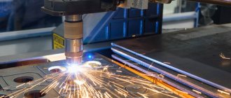
- Laser - the laser promotes the formation of high temperatures, which are directed to a specific sawing site. A very progressive method.
- Plasma is the best and most accurate method, in which the excess substance at the melting site simply evaporates, leaving very clean edges.
Cutting is also carried out using turning, milling and other equipment - the top layer is removed using the cutting edge of the tools.
Comparative table of cutting conditions on different machines
| Type of transaction | What parameters need to be controlled? |
| Turning |
|
| Milling |
|
| Drilling |
|
| Gear cutter |
|
| Grinding |
|
Thermal operations of metal machining
Many results require heating the element followed by cooling. This allows you to increase strength, change the crystal structure, and also perform deformations, for example, forging. The following types of heat treatment are distinguished.
Annealing
As a result of an increase in temperature to the plastic limit with a subsequent decrease in heat, the hardness decreases along with the furnace, but it becomes easier to process the part. Often used before stamping or forging.
Hardening
This is a similar procedure, but it includes one more stage - the increased degrees are kept long enough for the structure to stabilize. And cooling occurs not slowly, but quickly - in mineral oil or simply in water. This is necessary in order to relieve internal stress formed after casting, as well as for such elements that experience constant mechanical stress during operation.
Vacation
This is reheating after hardening, which allows you to consolidate all the manifested qualities, but at the same time reduce increased fragility. Reheating is much less intense.
Aging
Artificial stimulation of processes that occur with standard changes over time is rarely used.
Normalization
This is a change in structure - if initially after casting the chemical lattice has large grains, then after the operation it becomes fine-grained. This greatly increases malleability, but strength is not compromised. In the article we talked about different technologies for machining metal and showed photos. To complete the topic, let's watch a short video.
Operating technology of machining: specifics of development
When choosing the optimal option for the sequence of machining of metal products, two main factors must be taken into account:
- type of production;
- requirements that the quality of the processed part must meet.
At enterprises specializing in the production of single products, technological operations include many transitions and installations. This necessitates the need to frequently change metal-cutting tools and adjust them, which leads to an increase in auxiliary time and other consequences.
Enterprises that produce parts in batches are characterized by technical processes in which operations of the same name are divided into main and auxiliary transitions. In one operation, reinstallation of the workpiece is not provided, and the cutting tool is changed a minimum number of times, which reduces the time for its adjustment.
It will be possible to assess the requirements for the quality of the finished part when creating a technical process for machining a part if a number of aspects are taken into account.
For example, a technical process must obey a structural diagram. Each stage of operating technology is inextricably linked to the machining method and its accuracy. If it is necessary to obtain a surface layer of a part with a hardness of more than HRC 35, it is necessary to replace the blade tool with an abrasive one during the work. Go to list of articles >>
Milling work
Milling of parts is rightly considered the most difficult part of the technological process for the production of metal structures. Various types of cutters are used as cutting tools, which are divided into:
- end;
- cylindrical;
- disk (cut-off and groove);
- shaped - with a radius and angular (for inclined surfaces);
- modular and others.
Modern milling machines allow processing of vertical, horizontal and inclined planes of a part, as well as grooves and shaped surfaces. In this case, the workpiece moves forward, and the cutter rotates.
Machining of a part can be:
- passing,
- oncoming
Climbing is usually used during the finishing pass, but just as often the part is transferred to the grinding area for final finishing of the surface.
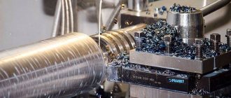
Turning machining
During the process of turning a workpiece, it rotates, and the turner removes excess layers of metal from it using a progressively moving cutter, gradually giving the product the required dimensions and the desired shape. When roughing a part, the feed speed and depth of cut are higher than when finishing.
Final processing of the workpiece requires a higher rotation speed and slow feed of the cutter. In this case, the cutter is selected with a new replaceable insert (sharper, capable of ensuring high processing accuracy and, therefore, low surface roughness).