At MetiStr LLC you can order metal processing of any complexity:
MetiStr LLC performs all types of metal machining. It is possible to carry out individual orders, as well as mass production. The company has its own fleet of equipment for machining workpieces with impeccable accuracy, in accordance with drawings and design estimates. Our company has been operating in Moscow since 1992. We do everything to maintain our reputation as a reliable partner, confirmed by available reviews and a gallery of completed projects. Continuous quality control is carried out at all technological stages. Meeting order deadlines is a priority for our company.
Types of metal machining
Mechanical processing of metals involves several basic operations. This:
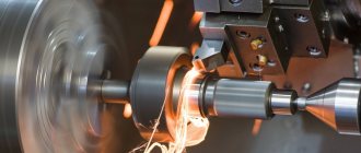
- Boring. This processing allows you to create bodies of revolution, as well as modify helical and spiral surfaces.
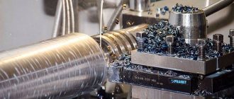
- Milling. Allows you to create various parts of any complexity and shape. Milling work is carried out using high-precision machines.
- Drilling. This metalworking operation allows you to create holes with the desired depth and diameter.
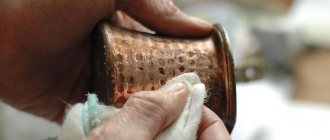
- Grinding. This mechanical processing of metal consists of finishing and finishing preparation of products. Grinding wheels are used for operations. They make it possible to remove a thin layer from a metal part.
- Chiseling. This type of machining involves working with planes and shaped surfaces. Slotting machines are used to perform operations.
- Planing. During this processing, operations are carried out with planes and ruled surfaces. The metal is cut on special planing machines.
There are other options for metal work. To provide each service, modern high-precision machines are required. The quality of mechanical operations largely depends on the experience of the specialist. That is why we strongly recommend that you trust their implementation only to professionals!
Welding
This type of metal processing, such as welding, is used when it is necessary to obtain permanent connections between metal elements. This technology is used everywhere (in large and small enterprises, in the repair of metal structures). You can connect parts in different ways:
- overlap;
- joint to joint;
- corners.
Metal processing in this method is carried out on semi-automatic or automatic welding machines, using hand tools. An electric arc or gas flame is most often used as a heat source. Less commonly, the joining of parts occurs due to thermal friction, ultrasound, laser energy or another type of influence.
Automatic machines do not have wide functionality. The operator presets the program. This is where human participation in the process ends. This method is used in the manufacture of a large number of products.
When working with semi-automatic equipment, the process is controlled by the operator, and additives are supplied to the desired zone through a special mechanism.
Over the last century, many new types of welding have been developed. Plasma, electro-beam and thermite technologies have gained popularity. In the first case, the parts are connected with ionized gas, forming an electric arc. In addition to welding, this type of equipment can cut metal workpieces.
If you need a deep (up to 20 cm) or small (up to 10 mm) seam, it is better to use electro-beam technology. Its specificity lies in the fact that metal processing occurs in a vacuum. This welding method is used infrequently, which is explained by its specifics.
Thermite type of welding is used:
to eliminate cracks and defects in previously made seams; if you need to ensure high quality connections of metal structures.
Prices for metal machining
| Name of service | Prices |
| Metal machining with thread cutting | from 300 rub. |
| Mechanical processing of metal with milling of planes and grooves | from 400 rub. |
| Mechanical processing of metal with boring of parts according to specified coordinates | from 500 rub. |
| Mechanical processing of metal with countersinking, reaming and drilling of holes | from 600 rub. |
Types and methods of processing materials.
Familiarize yourself with the material. Write down the types of processing and their definition.
Marking
is the operation of applying lines to the workpiece being processed that define the contours of the part or processing location. Markings on the workpiece are made in accordance with the drawing of the finished part.
Depending on the marking operations performed, various marking tools and devices are used.
Blanks are installed on the marking plate for drawing contour lines and places to be processed. Marking plates are cast from cast iron and have a carefully machined surface. The workpieces are installed on the slab using special jacks and linings. For ease of use of the stove and to protect its treated surface from damage, the stove is periodically wiped with graphite powder, and after completion of work it is covered with a wooden case.
In fig. 415 shows a marking plate mounted on a stable wooden stand.
A scriber is a tool used to draw lines on a workpiece to be marked. The scriber is made of hardened steel wire in the form of a thick needle, one end of which is bent at an angle of 90°; both ends of the needle are pointed. For ease of use, a thickening is made in the middle of the needle (Fig. 416, a).
The punch is used to make recesses on the workpiece in places to be drilled and on marking lines for better visibility. The center punch is made of hardened carbon steel; its shape is cylindrical, one end is pointed at an angle of 60°, the other end is blunt (Fig. 416, b). During operation, the punch is installed with its sharp end normal to the surface of the workpiece; the blunt end is struck with a hammer.
Using a thicknesser, lines are drawn on the workpiece to be marked. The thicknesser consists of a stand with a vertical stand; a clamp with a scriber fixed in it moves along the stand (Fig. 416, b). To make it easier to install the scriber at a certain height, divisions can be applied to the thicknesser stand. Thicknessers that have racks with divisions marked on them are called gauge thicknessers (Fig. 416, d).
The marking square is used to draw a vertical line; its short side has a T-section, which ensures the stability of the square on the marking plate (Fig. 417, a).
Malka is used to draw lines at the required angle; The malka consists of two steel rulers connected by a hinge (Fig. 417, b).
Marking compasses are used to draw circles on marked workpieces; its device is shown in Fig. 417, v.
A center finder is used to find the center on cylindrical workpieces (Fig. 417, d). The center finder is a square to which a ruler is attached, one of the sides of which divides the corner of the square in half. The square is brought into contact with its sides with a cylindrical workpiece; with this installation of the center finder, its ruler divides the circumference of the end of the workpiece in half. After moving the ruler to an arbitrary angle, draw a second line along the ruler. The intersection point of the lines drawn at the first and second position of the ruler determines the position of the center of the workpiece circle.
Chopping
produced using a chisel or cross-section. In fig. 418, and a drawing of a chisel is given, and in Fig. 418, b - drawing of the crossmeisel. As can be seen from these drawings, the crossmeisel differs from the chisel in the shape of the working head. The sharpening angle a of the chisel and crosspiece decreases with decreasing hardness of the metal being processed; its value falls within the range of 70-45°.
The chisel is used in all trimming operations with the exception of cutting out nests, keyways, etc., which are performed with a cross-cut tool.
Chisels and crosspieces are made of carbon steel.
Cutting with a chisel or cross-cutting tool is carried out by striking them with a plumber's hammer.
The product to be cut is clamped in a bench vice. There are vices
chair (Fig. 419, a) and parallel (Fig. 419, b).
cutting
During metalworking, metal is produced with a hacksaw or scissors. A hacksaw consists of a hacksaw blade and a machine.
Hacksaw blades are made from steel strips 200-300 mm long, 11-16 mm wide and 0.5-0.8 mm thick: 5-12 teeth are cut over a length of 1 cm. A manual hacksaw is used for cutting materials of small diameters; when cutting workpieces of large diameters, powered hacksaws are used. Scissors are used to cut sheet material up to 5 mm thick.
Filing
called a metalworking operation used to obtain a smooth surface of a part after chopping or cutting. Filing is done with files. Files are made from steel strips with teeth cut on them (manually with a chisel or using a special gear cutting machine). After notching, the files are subjected to hardening or carburization, followed by heat treatment. Files are made in various profiles and sizes.
According to OST 320-325, the length of files is 100-450 mm with a width of 4-45 mm. In fig. 420 shows the main types of files. Depending on the nature of the filing operation and the material being processed, different types of files are used.
For processing babbitt, lead, leather, wood, etc., rasps are used (Fig. 420, 9), having 2-6 notches per 1 linear line. cm.
For rough stripping of metals, blocks are used (Fig. 420, 1), having 4-6 notches per 1 linear line. cm.
For rough filing, hog files are used (Fig. 420, 2); number of notches 5-12 per 1 cm.
For finishing filing, semi-file (Fig. 420, 3 and 4) and personal (Fig. 420, 5) files are used with the number of notches for the first 12-18 and for the second 18-26 per 1 running line. cm.
For final finishing and precision work, velvet files (Fig. 420, 6 and 7) with a number of notches of 26-40 are used.
For sawing out shaped holes and for minor work, needle files are used (Fig. 420, with a number of notches of 50-80 ka 1 cm in length.
The quality of filing work depends on the correct use of the file. One of the main requirements for working with a file is to ensure that the movement of the file is parallel to the surface being processed. The position of the mechanic's hands when working correctly with files is shown in Fig. 421, where a—work with a bastard file, b—with a velvet file.
Manual drilling
. Drilling is the operation of making holes in the material being processed. The tool by which this operation is performed is called a drill. Drills are divided into feather drills (Fig. 422, a) and spiral drills (Fig. 422, b).
The cutting edges of the feather drill form an angle of 90° or more. The angle between the back edge of the drill and the machined plane, i.e. the back angle, is 10-25°. To reduce the cutting angle to 70-80°, a groove is cut out on the front edge.
Feather drills are simple and cheap to manufacture: the end of the rod is pulled back and forged into a blade shape, then hardened and sharpened.
Their disadvantage is the inaccuracy of processing, in particular, due to the deviation of the drill axis from the axis of rotation. In addition, when working with a feather drill, chips clog the resulting hole and spoil it, which makes it necessary to periodically interrupt work to remove chips.
A twist drill is a round rod with two helical flutes. The grooves serve to remove chips. The angle of inclination of the helical flute to the axis in normal drills is 30°. Narrow strips called ribbons or chamfers are made on the cylindrical surface of the drill along the helical grooves.
A twist drill consists of a working part 1 (Fig. 422, b, c) and a shank 4. The shank is used to secure the drill and has a cylindrical or conical shape; At the end there is a foot 5.
The working part of the drill has helical grooves and a cutting part 2, which is a cone with two cutting edges.
There are ribbons 3 along the screw grooves of the drill. The cutting part of the drill (Fig. 422, c) has a back surface 1, a bridge 2, a cutting edge 3, a groove 4, a chamfer 5.
When working with twist drills, the holes are more regular and clean than when working with a feather drill. When working with twist drills, chips are collected and discharged automatically by screw grooves. Twist drills can be re-sharpened without changing their diameter.
The disadvantage of twist drills is that they are difficult to manufacture. Sharpening twist drills should be done using templates.
The operation of processing holes found in cast and forged workpieces or obtained by drilling is called countersinking. Countersinking is carried out in order to increase the diameter of the hole and is carried out with a countersink. A small countersink (up to 35 mm) is made solid (Fig. 423, a) and differs from an ordinary drill in a large number of grooves (usually four) and a blunt end. Large countersinks are made mounted (Fig. 423, b), for operation they are mounted on a mandrel made of machine-made steel. To process the exit part of the holes, specially shaped countersinks are used - countersinks; in fig. 423, c shows a countersink used for countersinking holes for the conical head of a bolt.
Bringing the drilled holes to the exact size is done using reamers (Fig. 423, d). Reamers differ from countersinks in a large number of grooves.
When working with drills, various types of devices are used: ratchets, hand and mechanical drills (Fig. 424, a, b and c).
When processing steel parts, the drill is cooled with oil or soapy water; Bronze and gray cast iron are drilled without the use of coolants, since when processing these materials, small chips are formed, which, together with the liquid, turn into a very viscous mass, which greatly increases friction.
Thread cutting.
A tool used in plumbing for cutting threads in holes is called a tap.
A tap is a screw with several grooves along its axis, forming cutting edges. Taps can be cylindrical or conical. The tap device is shown in Fig. 425; The thread formed by the tap is determined by the thread profile of the tap, the angle a of this profile, the pitch S, the outer diameter D, the inner diameter D1. Bench taps are used in sets of 3 pieces: roughing, semi-finishing and
stand. The first serves to pre-form the cut, the second deepens the cut made with a roughing tap, and the third finishes the thread.
The roughing tap has a thread with cut off tips, the semi-finishing tap has a less cut thread, and the finishing tap has a full thread. Threading is done with a tap in a pre-drilled hole. The diameter of this hole should be slightly smaller than the internal diameter of the thread. During operation, the tap is screwed in one turn, after which it is given half a turn in the opposite direction; This technique achieves chip crushing and makes the work easier in general.
To obtain a cleaner thread surface in steel products, taps are lubricated with oil (sulphurized or vegetable); When cutting threads in cast iron and bronze products, no lubricant is used.
Dies are used to cut threads on rods.
Dies are round or square plates with a central hole with a thread; To form cutting edges, slots are made in the cutting. The arrangement of round dies is shown in Fig. 426, a, dies for oblique dieheads, consisting of two halves - in Fig. 426, b. When cutting threads, the dies are secured in a special device called a clamp (Fig. 426, c).
The die consists of a frame in which the dies are secured with a screw clamp. The klupp has two handles that rotate it.
To cut threads on rods of small diameter, screw boards are used, which are a hardened steel tile with threaded holes cut in it (Fig. 426, d); it has a handle to rotate the screw board.
Scraping
called oneration of obtaining very clean surfaces by removing a thin layer of metal from them by scraping; the tool used for this purpose is called a scraper. The scrapers can be straight or curved, and their cross-sections can be flat, triangular or rounded. In fig. 427, and various scrapers are shown, and in FIG. 427, b - position of the scraper during operation.
The scraping process is carried out as follows: 1) before scraping, a thin layer of paint (red lead, soot, whitewash) is applied to the surface plate; 2) the surface to be treated is placed on a slab and slightly moved along it, as a result, a layer of paint adheres to the elevations of the surface to be treated, while other places remain clean; 3) the painted areas are treated with a scraper. This operation is repeated until the paint evenly covers the entire surface to be treated. Then the paint is removed from the surface plate, the plate is wiped dry and the product is moved along the surface plate; in this case, the elevated areas of the products are indicated by light spots. The quality of scraping is judged by the number of such spots per 1 cm2 of the surface being treated; treatment is considered good if the number of spots is 5-6 per 1 cm2.
The scraping process is very labor-intensive. To mechanize it, special devices are used that significantly increase productivity and make the worker’s work easier. In fig. 428 shows a scraping machine.
Advantages of contacting our company
- Experience of specialists. We have been performing mechanical processing for several years. Specialists successfully solve numerous problems. They are ready to advise clients and provide answers to any questions they may have.
- Compliance with all established standards and regulations.
- Accounting for all customer requests. When it comes to machining, we are ready to meet any of your requirements.
- Optimal cost of metalworking services.
- Efficiency in solving problems. You can check the exact timing of mechanical metal processing operations in Moscow in advance with our company.
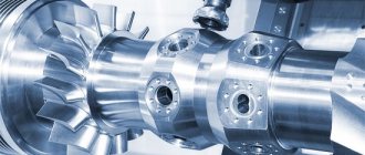
- Availability of modern equipment. Metal processing is performed using CNC machines. They allow you to quickly perform all necessary operations and achieve optimal performance parameters of the resulting products and structures.
Processing by pressure and cutting
Metal forming is part of the group of artistic methods. In addition to changing the shape of the workpiece, it can be stretched or compressed. This method is used to make not only decorative items, but also wheelbases and gasoline tanks.
When cutting, the metal is divided into parts of the required size. A profile of standard width and thickness from medium-strength alloys is most often made using an abrasive wheel or circular saw. If you need to cut a workpiece of a more complex shape or process a durable workpiece, use other cutting methods:
- manual;
- gas;
- laser;
- plasma.
To cut one or more blanks, it is better to use a hand tool. It consumes less electricity than a machine or does not require connection to a power source at all. You won't be able to save a lot of time. The machine needs to be prepared for startup, parameters must be set.
Metal gas cutting is used when it is necessary to make many parts in a short time. This method is also convenient if the workpieces need to be placed in a container for transportation.
Laser processing is multifunctional. In addition to cutting using special equipment, you can apply an inscription to the workpiece. When cutting with a laser, the dimensions of the resulting parts correspond to the specified parameters. It is better to treat hard metal with plasma.
Heat treatment of main types of cutting tools
Here are the heat treatment regimes for widely used types of cutting tools.
Image No. 5: table with designations of heat treatment parameters for cutting tools
Drill
In order for the drill bridge to be hardened along the entire length of the working part, the equipment is subjected to through hardening along the cross section. In this case, make sure that the depth of the hardened layer is not less than half the thickness of the jumper at a distance of 100 mm from the end of the drill.
Drills are heated in lead and salt baths or ovens. To reduce the tool drive:
- drills are heated in a vertical position;
- small drills (up to 10 mm in diameter) are cooled in hot environments using the isothermal hardening method;
- large drills are immersed vertically in oil and removed while still hot;
- When hardening, carbon steel drills are immersed in water until completely cooled.
Taps
Features of heat treatment of cutting tools such as taps are determined by the specifics of their use. In a tap, the working layer is the surface layer, while the core of the tool must remain viscous.
When processing taps, follow these recommendations:
- the heating temperature during hardening is set at the lower limit;
- The holding time during hardening is set short, sufficient to warm up the surface layer;
- to reduce heating time, lead and salt baths are used;
- carbon steel taps are cooled in water for 4–8 s, and then in oil;
- Taps with a diameter of up to 10 mm are cooled in oil.
Dies
To prevent breakage of the dies, their bridges must remain as viscous as possible. Therefore, the dies are heated in several stages, with short shutter speeds. The dies have sharp transitions in cross-section, therefore, to protect them from cracks, sudden heating and rapid cooling during hardening are avoided.
When heat treating this type of cutting tool, the following recommendations are followed:
- the dies are heated in a salt rather than a lead bath;
- large products are cooled in hot environments (carbon steel dies in hot oil, alloy steel dies in molten salts);
- cooling is carried out in pliers-cartridges, which allow you to leave the cutting part open and the cylindrical part closed;
- jumpers with sharp transitions are insulated with asbestos before heating;
- The dies are released for a long time to relieve the stresses generated during hardening.
Milling cutters
Heat treatment of medium-complexity cutters (cylindrical, disk, etc.) is carried out at a slow pace. If final heating is performed in salt or lead baths, the instruments are first heated at a temperature of +300 - +400°. The heating hold ensures through-heating of the cutters, since cooling occurs with the same intensity from both the outside and the inside. If the surfaces do not warm up enough, uneven stresses will arise during cooling, which will lead to the appearance of cracks.
Countersinks and reamers
Heat treatment of these cutting tools is carried out according to the same principle as taps. During cooling, the reamers are protected from possible deformation; for this purpose, media such as heated oil and low-melting salts are used at a temperature of +150 - +170°.
The hardening of stepped reamers, which have different diameters of the working part along the length, requires more attention. To prevent cracks from appearing on the metal, first the thinner part is immersed in water, after 2-3 seconds the middle part is immersed, and only then the entire working part is immersed.
Grinding Features
Machines for this type of processing are used for internal and external grinding of round surfaces, different planes, centerless machining, threads, gears and much more. Such a tool for metals belongs to the category of the most productive. In addition to the special machine, there is one more device. This is a grinding wheel that includes a large number of small cutting elements. They, in turn, are fastened with a special connecting device. And each particle itself is a cutter. As you can see, we looked at metal processing equipment. Below we will get acquainted with more modern techniques that allow cutting it.
Features of the use of machines
Metal-cutting machines are divided into types. They differ in the tool used. Also, the technology for processing metals by cutting with their help is different. The most commonly used tool is a cutter. With its help you can perform operations of any complexity. All other instruments are either its modification or a combination of several types. There are two most common operating schemes:
- turning, when the workpiece rotates and the cutter slowly moves along its axis;
- planing - they both move in translational movements.
The machines they require are completely different.