External networks
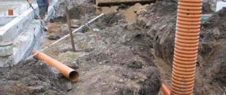
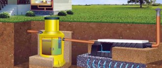
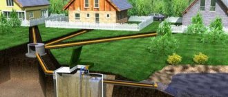
External networks and structures are considered to be sewerage facilities located outside the home. These include pipes, septic tanks (cesspools), and treatment facilities.
When preparing a drainage project, it is important to take into account the unevenness of wastewater discharge and the maximum throughput in case the water supply system is used to the maximum and a burst discharge is carried out. In addition, SNiP proposes to take into account the amount of rainwater that does not enter the sewerage system in an organized manner.
All coefficients are calculated and printed in SNiP 2.04.03-85.
What does the external sewage system consist of?
The sewerage system laid outside the building has a complex design, including bends with pipes, inspection hatches, slopes, and containers. Installation is carried out in accordance with the requirements of SNiP, taking into account safety precautions.
The sewerage system consists of such elements as:
1.pipeline, which contains pipes of different sizes and lengths.
2. wells, their number depends on the situation, there are:
-revision type.
- drainage type.
-variable type.
- rotary type.
4.releases and receivers. Through outlets, waste water flows into a cleaning tank.
5.local treatment structures: septic tanks or aerators. The number of treatment facilities is determined by the regulations. After the cleaning procedure, wastewater is absorbed into the ground or flows into water bodies. Sometimes it is collected in containers for further use in everyday life.
Attention! Autonomous sewerage must include a septic tank or aerator.
5.pumping station. These structures are not used for all types of sewage systems, but are used only when it is necessary to supply wastewater for treatment in parts.
6. from elements that help the system operate, for example, installation equipment.
Classification of sewer pipelines
Utility drainage networks are divided according to their purpose and method of drainage.
Pipelines perform different tasks and carry wastewater collected from various sources. In the construction of drainage networks, different types of pipes of various diameters are used. According to their purpose, sewer pipelines are divided into:
- production;
- household No. 1;
- stormwater No. 2 (for melt and rainwater).
Types of external networks
For individual construction, household and stormwater communications are relevant; they are most often arranged by the owners on their plots. Afterwards, it is connected to city collectors, which are managed by public utilities.
There are two types of wastewater disposal:
- self-flowing;
- forced (using pumps).
Gravity drainage is carried out only due to the slope of the pipeline, while pumps are used for forced sewerage. The second option is justified when the flow of water into the septic tank is difficult, for example, when the house is located too far from the septic tank. In this case, a collection well is installed in which the pump is placed. This measure helps prevent water from stagnating in communications, which leads to siltation, unpleasant odors and congestion.
To ensure the reliability of utility networks, several methods are proposed:
- duplication of pipelines so that it is possible to switch to additional pipes;
- laying the diameter of the sewer with a reserve;
- modern power supply system, spare power supply.
Features of storm drainage
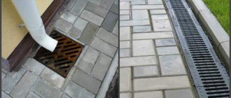
Stormwater is a network of channels in the form of trays that collect and transport rain and melt water from the roof and surface.
It comes in point and linear types.
As for the second option, according to building codes and regulations, the external pipeline must be installed at a slope towards the main collector.
This requirement applies to both closed and open storm sewers.
It is worth noting that if for some reason it is impossible to ensure the slope of the sewer pipes, then pumps are additionally included in the system.
Considering that it will not be possible to carry out gravity flow of sediments, the pumps will provide forced pumping of liquid.
Storm drainage trays
Classification by device method
External water supply and sewerage networks are divided into:
- general alloy;
- semi-separated;
- separate.
The general-fluid type is when all drains, economic, domestic and rainwater, flow together in one direction.
The semi-separate type is characterized by the fact that domestic and storm drains flow through separate pipelines into a single structure.
The separate type is almost never used in private construction, because it involves organizing the drainage of wastewater through different mains into different reservoirs.
Types of sewer networks
External sewerage networks according to the type of routing are divided into:
- aboveground;
- underground.
The construction of sewerage systems of the first type is prohibited in cities; installation of networks is possible only underground.
Based on the location of utility networks, they can be divided into:
- yard;
- intra-block;
- street
A yard sewer system is installed to serve one house. Its diameter is up to 150 mm. In addition, the network includes outlet, intake and inspection wells.
The intra-block network is an enlarged version of the previous one; several houses are united into it.
The street drainage network is designed to combine and remove wastewater from several intra-block systems. Such a branched object is called a collector.
Principles for determining the minimum slope
So, in order to determine the slope of a storm drain according to SNiP, attention is drawn to:
- type of water pipeline;
- diameter of pipes being laid;
- surface coating.
As for pipes d=150 mm, here the slope is already slightly greater, about 0.8 cm/m.
It is worth noting that the building codes also stipulate that if there is an urgent need, the slope in certain areas can be reduced. For 200 mm pipes the minimum value is 0.5 cm, and for 150 mm it should not be less than 0.07 cm.
The same document also regulates the maximum slope value; it is 1.5 cm/m.
Storm sewer pipe, diameter 200 mm
All rules and regulations must be followed, because otherwise the risk of clogging may increase significantly.
For example, if you make a very large slope, the water will drain too quickly, and accordingly, the sand settling from it will silt up the surface of the pipe from the inside.
Slope of open type storm drain
As for the slope of an open-type storm drain, its value is determined by the type of surface, for example, where the ditches are asphalt - 0.3 cm/m, and where with crushed stone and cobblestones, then 0.04-0.5 cm/m.
Sewage network diagrams
Before deciding on the design of external water supply and sewerage networks, the features of the site’s topography are studied. The following types of schemes are distinguished:
- perpendicular - characterized by the fact that almost all sources of wastewater are directly connected to the main highway for rapid redirection of water;
- zone - an infrequently used scheme, relevant for areas with significant differences in altitude;
- cross-section - the main collector is installed near rivers;
- radial - wastewater from the collector diverges to various treatment facilities.
Composition of utility networks
For proper operation of the sewerage system, it is necessary to ensure that the following elements are present in the system of external networks and structures:
- Pipes are the main highways through which water flows from houses, institutions and storm water inlets.
- Wells . There are reception, inspection, drainage, rotary, and the functions they perform differ.
- Outlets are sections of pipes that carry out wastewater from the internal sewerage system of buildings.
- Collectors are a set of concrete communications of significant diameter..
Design
If there are sufficient grounds for arranging the NK, you can proceed to the first stage of construction - system design. It is better to entrust this part of the work to specialists. They will calculate the pumping station, determine the optimal pump power and the need to install a switching chamber, draw up an accurate estimate and explanatory note, observing design standards. An example of such a project and installation estimates can be found on thematic sites and forums.
Note that when connecting to central sewerage networks, the operation service will first of all request a design for the drainage system. When organizing an autonomous NK, some of the problems are eliminated, but, nevertheless, there are nuances that must be taken into account.
Errors in hydraulic calculations, calculations of the minimum pipe diameter, engine power, etc. may lead to unstable operation of the internal or external NK network. In some cases, the situation can be corrected by creating a pressure damping loop (damper well).
Construction of a damper well
The number of such wells in the system is not standardized; their number, the distance between the two nearest ones and their characteristics are determined during the calculation process or based on the results of a hydraulic test. It is not as serious as for an oil pipeline, but, nevertheless, it must be carried out without fail for NK.
Selecting a fecal pump
First of all, it is necessary to determine its power; it depends on the length of the vertical and horizontal pipeline lines. This relationship is shown in the figure below.
Pump power depending on pipeline length
As for the flow rate in the NK system, according to SNiP standards it should be about 2.0 l/s; accordingly, the pump capacity is selected at 120 l/min. Next, you should decide on the type of pumping equipment, it can be:
- Submersible (suction).
- Superficial.
The first ones are more expensive, they are designed for trouble-free operation in an aggressive environment. The latter are somewhat cheaper and easier to maintain, but their installation will require more effort.
Tank volume
The volume is calculated based on the daily rate of water consumption per person, its average value is about 0.20 m3. The reservoir must hold a minimum of three days' flow. For example, if 4 people live in a building, the average daily consumption will be about 0.80 m3; taking into account the three-day norm, the tank must have a volume of at least 3.20 m3.
It is advisable to choose a two-chamber tank design, in which case one compartment will act as a primary settling tank, and the second as a pumping chamber. It is in it that a fecal pump equipped with a grinder will be installed. The filling of the tank is controlled by special sensors; when the wastewater reaches a threshold level, the pump is started to pump it out.
You can purchase a ready-made pumping station with a plastic tank or build a storage tank yourself from concrete rings or bricks and install the necessary equipment.
CNS: a) industrial; c) average power
Choosing a location for a storage tank
In order to avoid claims from the water utility, sanitary and epidemiological services and other regulatory organizations, you should take seriously the choice of location for the storage tank. In accordance with SNiP 020402-84, there must be a sanitary protection zone around a possible source of pollution. The above document stipulates what the minimum distance should be between the pipes (sleeves) of the NK and wells or other sources of drinking water. These SNiPs also regulate the distance from the security zone of residential buildings, site boundaries, bushes and trees, as well as other objects.
Basic norms for the place of pumping stations
In addition, you should take into account the underground communications passing through the site; unfortunately, their designation is not always present on the drawings, which can cause certain difficulties. Information about the availability of such communications can be obtained from the relevant services.
Pipe material
The selection of material for the installation of underground communications is one of the main points in drawing up a project for internal and external water supply and sewerage of residential buildings. It is necessary that they have good resistance to corrosion, the action of solid suspensions and the environment. SNiP considers the possibility of using the following pipes:
Selection of material
- Polyethylene;
- polyvinyl chloride;
- polypropylene;
- steel;
- cast iron;
- reinforced concrete;
- asbestos-cement;
- ceramic
- glass.
The use of the latter is permitted by regulations, but only in exceptional situations.
Reinforced concrete pipes
Used in non-pressure networks. They usually have a large diameter and are resistant to external influences, as well as compressive and tensile loads. They can be used to drain wastewater from industrial buildings, the main area of application is urban sewerage with a large volume of wastewater.
Asbestos cement pipes
Can be used not only in non-pressure networks, but also in pressure networks. The material can withstand loads well and is difficult to impact. As a result of interaction with the aquatic environment, its strength only increases.
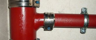
Steel pipes , although provided for by SNiP, are rarely used for underground sewers, as they are susceptible to corrosion.
Cast iron pipes
Widely used option. For a long time, only this material was used; its service life reaches 80 years. These are very durable pipes that are not subject to corrosion. They are mainly used for laying urban networks, but are sometimes used in private construction. The disadvantages include internal roughness, which contributes to build-up of solid particles contained in the liquid, large mass of the product and high cost due to the peculiarities of cast iron production according to GOST.
Polymer pipes
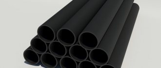
They have become widespread recently. They are made of polyethylene, polyvinyl chloride or polypropylene. These products are lightweight and can withstand loads well, so they are used in pressure and non-pressure networks. The advantages also include their lightness and relatively low cost.
The main disadvantage of PVC pipes is the small range within which they retain their performance properties. They do not tolerate high and low temperatures well, so when installing PVC pipelines it is necessary to provide thermal insulation. PVC pipes are rarely used for installing external utility networks, but they perform well when installing internal water supply and sewerage systems.
Basic requirements that must be observed when designing
To ensure high efficiency of communications and reduce installation costs, it is recommended to develop the sewerage system in parallel with the design of the external water supply system. The construction of the sewer network must be carried out in accordance with sanitary and hygienic standards. Therefore, the primary task of such a project is to determine the type of terrain and type of sewer system. According to one of the points of SNiP, it is necessary to determine the environmental features of the area where the new wastewater disposal network will be located. The main environmental factors include:
- soil feature. Setting this factor will allow you to determine the optimal type of sewage system for the area;
- ground water level. Its determination is mandatory, since if the water level is high, it is necessary to take a number of additional measures before laying the pipeline;
- climatic conditions make it possible to determine the need for thermal insulation materials for the pipeline.
After establishing environmental factors and determining the type of sewer, some of its technical characteristics should be taken into account. In particular, the maximum volume of wastewater and the distance from the communication line to the object. Additionally, according to SNiP, it is necessary to determine the method of passing sewage pipes through water barriers or ravines, if such obstacles exist in the path of the future sewer network.
Basic rules for sewerage installation
In order for the sewerage system to fulfill its functions, to avoid blockages, deformations and leaks, the joint venture provides a number of recommendations that must be taken into account both at the stage of preparing schemes and projects, and directly when installing external sewerage networks.
You may also like - Sewerage in a private house - do-it-yourself step-by-step installation
Pipe diameter
One of the main characteristics of pipes is their diameter. This setting affects network throughput.
SNiP indicates the smallest permissible parameters of pipes:
- street network – DN 200 mm
- intra-block – DN 150mm
- street and intra-block storm drainage – DN 200 mm and 150 mm, respectively;
- when no more than 300 m3/day of water enters the sewer, it is possible to use pipes with a diameter of 150 mm.
Estimated water flow speed
To prevent pipes from silting, it is necessary to take into account the speed at which the drains move, the filling of the system and the presence of suspended solids. These data are contained in the SNiP tables, and for external sewerage DN 150-250 mm they are as follows:
- minimum speed: 0.7 m/s;
- maximum speed: 8 m/s and 4 m/s for metal and other pipes;
- for storm drainage: 10 m/s and 7 m/s for metal and other pipes, respectively.
Pipeline slope
Slope is a critical parameter when preparing design documentation and carrying out work. This is especially true for self-flowing systems in which the movement of wastewater occurs under the influence of gravitational forces. If the correct slope is not maintained, the sewer system will not function correctly, this will lead to stagnation of drains, unpleasant odors, siltation and congestion.
The slope is calculated as the ratio of the difference in the depth of the pipe to one meter of its length.
| Name | Regulatory bias |
| Asphalt coated trays | 0,003 |
| Trays coated with paving stones, crushed stone | 0,004 |
| Cobblestone street | 0,005 |
| Separate trays and cuvettes | 0,006 |
| Drainage ditches | 0,003 |
| Trays made of PVC and polymer concrete | 0,001-0,003 |
For utility networks installed in a small house, for example, a townhouse, and occupying a smaller area than city ones, the following values are accepted:
| Diameter | Slope |
| 50 mm | 30mm/1000mm |
| 110 mm | 20mm/1000mm |
| 160 mm | 8mm/1000mm |
| 200 mm | 7mm/1000mm |
If the terrain does not allow otherwise, the slope can be reduced to 0.007-0.008.
Storm water inlet networks enter the general sewer system with a slope of 0.002.
You may be interested in the article - Slope of sewer pipes according to SNiP
Device depth
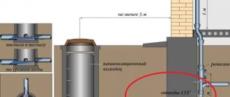
Critically low or high temperatures have a negative impact on pipes. In addition, in winter, when the pipes are buried high, the liquid in them can freeze, forming ice plugs. The depth is determined as a result of technological calculations and taking into account data on the terrain of the area in which the pipeline is being installed. Usually it is laid at a depth of 0.5-0.8 m below the soil freezing level.
When determining the depth, the following are also taken into account:
- material;
- diameter;
- soil type;
- installation method.
The base for communications is selected after studying the bearing capacity of the soil. If installation is not carried out in swampy areas, not on rocky, quicksand or subsidence soils, then the pipes are laid on the prepared trench bottom.
In rock formations, a sandy base is made. minimum 100 mm, which prevents damage to the material. As a rule, local fine sand is used for its construction. For swamps and subsidence soil, an artificial foundation is installed, which is much stronger and does not allow the network to sag.
For pressure pipelines, it is recommended to provide for the installation of fittings.
Calculation of storm sewer slope: SNiP standards
Every homeowner is familiar with the consequences of heavy rainfall and spring snow melt.
And if, at the stage of constructing a private house, you do not take care of the construction of a storm drain on the site, then all this can result in serious problems.
Such measures will help prevent the formation of a swamp in the yard, flooding of the basement and foundation, and at the same time, it will protect the walls of the house from destruction from the outside.
The content of the article:
Storm drainage in the house
Manholes
Inspection wells are a concrete or polymer structure, an important object of the sewer network. It allows you to quickly access its most important areas, those places where leaks and damage are likely.
Inspection well
Inspection wells are provided in the following places:
- connection points;
- installation of fittings;
- change of direction, diameter or slope;
- on extended sections with intervals: 150 mm – 35 m;
- 200/450 mm – 50 m;
- 500-600 mm – 75 m;
- 700-900 m – 80 m.
Manufacturers offer prefabricated reinforced concrete wells of various configurations and parameters. The size of a rectangular well is selected based on data on the diameter of communications:
- up to 600 m – 1x1 m;
- from 700 mm – length DN+400 mm, width DN+500 mm.
But the most common wells are those with a round neck. They are the most convenient to use. For them, SNiP specifies the following parameters:
- 600 mm – 1 m;
- 700 mm – 1.25 m;
- 800-1000 mm – 1.5 m;
- 1200 mm – 2m.
All wells should be provided with the possibility of descent and fenced off if the diameter exceeds 1200 mm.
Network ventilation
Ventilation of the sewer system is arranged to eliminate unpleasant odors and prevent them from entering the house. Exhaust ventilation is installed together with the internal risers of the building. The rules for its installation are regulated by the joint venture “Internal water supply and sewerage”.
The ventilation pipe rising above the roof of the house is protected by an umbrella and has a design height such that roof slopes and wind flows do not interfere with air removal.
Laying depth according to SNiP
SNiP standards indicate the depth of gravity sewerage for individual houses. It differs for different climate zones. For the climate of the Moscow region and Sochi, these indicators are different. This is, of course, connected with avoiding freezing of drains. You can understand what SNiP recommends on this topic from the standards common to all climatic zones. Namely:
The laying depth of sewer pipes at the exit from the building should be 30 cm higher than the average annual freezing point.
But in any climate no less than 70 cm.
In reality, it is impossible to take into account the depth of freezing. In most climatic zones north of Voronezh it reaches 2 m. Therefore, according to SNiP, the pipe at the exit from the house should be at a depth of 200 cm - 30 m = 170 cm.
A depth of 1 m 70 cm is not justified and is unnecessary even in the northern regions. In addition, it should be taken into account that at the other end, due to the slope, the pipe will be even lower.
