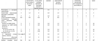
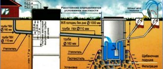
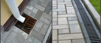
Trench width
along the bottom should be at least
40 cm
larger than the outer diameter of the pipeline.
For dense and hard soils at the bottom of the trench, before laying pipes, a bed of sand with a thickness of at least 10 cm
.
When backfilling the pipeline
A protective layer of sand or soft local soil, at least
30 cm
and not containing crushed stones, stones, etc.,
Tamping and compacting the soil in the sinuses
between the trench wall and the pipeline, as well as the entire protective layer, is performed manually with a non-mechanized tool.
When filling up the sinuses
and the installation of a protective layer of soil, pipeline connections are left uncovered until PRELIMINARY TESTS for tightness.
Filling the sinuses and compacting the soil in the pits is carried out using a tamper.
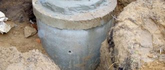
Installation of units in a well
carried out simultaneously with the laying of the pipeline.
The pipeline is connected to the flanges before backfilling the pipeline with a protective layer of soil, without tightening the bolts.
READ ALSO: PRODUCTS FROM QUARTZ AGLOMERATE
Final tightening
bolted connections are performed immediately before hydraulic testing of the system.
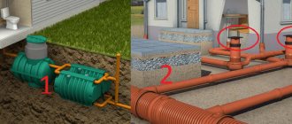
What is a sewer outlet
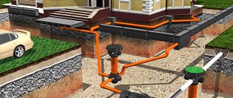
So, sewer outlets and collection pipelines, what they are and what they are used for. There is no exact definition, but its essence is not difficult to explain. Any system includes two sections - internal and external sewerage. The first group is all the pipes located inside the house. The second is the external, underground part of the system, which is connected to the collector or septic tank. A sewer outlet is a node that connects a vertical riser to a horizontal external line. It is a prefabricated part made up of several fittings for the smoothest possible bending of the pipe. The upper part of the outlet is connected to the riser, the lower part is connected to the underground pipeline of the external section of the system. The design of this unit is not complicated; it includes the following elements:
- pipes of the appropriate diameter for assembling the unit and making sleeves;
- tee;
- tap;
- end cap.
The easiest way to understand what a sewer outlet is is by considering the diagram of its assembly and connection. In the figure, the node is marked with a red oval:
It must be borne in mind that the sewer outlet shown in the figure is a design option for a multi-story (apartment) building. The option for an autonomous system is somewhat simpler. In particular, it is not recommended to make an inspection hatch in the basement, since if a blockage occurs, drains will gush out of it and flood the room. The inspection should be placed above the plumbing fixtures on the first floor.
In private houses, you cannot leave open sections of pipes located between the ceiling and the ground. This will create all the conditions for freezing and stopping the system. It is necessary to use an insulated area that is not in contact with the cold air of an unheated basement.
A riser is attached to the top of the assembly. Its end on the upper side is a drain pipe, an exhaust ventilation element of the sewer system.
Plastic or cast iron elements are used for assembly. Their minimum size must be equal to or exceed the diameter of the sewer riser (pipes Ø100 mm are usually used). Reducing the diameter is strictly prohibited, as this will cause permanent blockages to appear.
You may also like:
Do-it-yourself sewerage from concrete rings
Teleinspection of sewerage: what is it, types, possibilities of the method
What is a sewer outlet and who should maintain it?
Question :
What is a sewer outlet and who should maintain it?
Answer :
Sewer outlets are a system of pipelines from the sewer network (sewer risers) of basements to the axis of the inspection well.
Maintenance of sewer outlets should be carried out by a management organization or homeowners association.
According to clause 1.4. SNiP 2.04.01-85:
“Internal sewerage is a system of pipelines and devices in a volume limited by the outer surfaces of enclosing structures and outlets up to the first inspection well, ensuring the removal of wastewater from sanitary fixtures and technological equipment and, if necessary, local treatment facilities, as well as rain and melt water in sewerage network for the appropriate purpose of a settlement or industrial enterprise.”
According to clause 5 of the Rules for the maintenance of common property in an apartment building, approved by Decree of the Government of the Russian Federation of August 13, 2006 N 491, it is determined that the common property includes an in-house engineering drainage system, consisting of sewer outlets, fittings (including bends, transitions , branch pipes, revisions, crosses, tees), risers, plugs, exhaust pipes, drainage funnels, cleanings, branches from the risers to the first butt joints, as well as other equipment located in this system.
According to clause 2_3. Art. 161 of the Housing Code of the Russian Federation: “When managing an apartment building with a management organization, it is responsible to the owners of the premises in the apartment building for the provision of all services and (or) performance of work that ensure the proper maintenance of the common property in this building and the quality of which must meet the requirements of technical regulations and the rules established by the Government of the Russian Federation for the maintenance of common property in an apartment building.
Source
Norms
Sewer discharge is done according to certain rules. They are listed in SNiP 2.04.01-85, or in their more recent edition SP 30.13330.2016. These regulatory documents detail all the conditions for correct assembly of the unit and define the maximum and minimum values of all parameters. The main requirements include:
- The laying depth of external pipes must exceed the soil freezing level. The sewer outlet from the building must comply with this requirement. If it is not possible to lay the line at such a depth, you will need high-quality insulation of the pipes and outlet. The installation of the heat insulator is done on the very floor of the lower floor;
- When calculating the depth, the slope should be taken into account. It is only 2 cm for every meter of horizontal line. However, if you do not take this value into account, you may make a mistake when connecting the line to the manhole;
- the length of the sewer outlet from the outer wall to the inspection well should not be less than 3 m;
- it is prohibited to locate open sections of the system in an unheated basement or basement;
- it is necessary to make a minimum number of bends along the route of the drains;
- the minimum distance between sewer outlets is 40 cm. Experts do not recommend making several nodes; it is more correct to first combine all the lines into a single riser, and then take it outside the walls of the house.
Following the standards and rules will ensure stable operation of the system.
Installation of the outlet connection with the yard sewerage
It is advisable to install the external part of the sewer system from the well of the system. This will avoid clogging.
When laying pipes it is important:
- Maintain the slope;
- Mount the pipe inside the well flush with its diameter. Thanks to this, the drains will flow slowly, without eroding the bottom;
- To connect pipes inside the well, use a special tray;
- If it was not possible to lay the sewer system below the freezing level of the soil, do not forget about insulation.
After all work is completed, the operability of the structure is checked and at the end the sewer outlets are sealed.
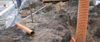
Installation procedure
Let's look at how to do it yourself when draining a sewer from a building to the first well. The procedure is not complicated, but requires strict adherence to the instructions. Procedure:
- At the required depth, a through hole is made in the foundation. Its diameter should be 200-250 mm larger than the size of the sewer pipe. The walls are covered with a waterproofing compound (bitumen mastic is suitable). Then a sleeve is inserted into the hole, the length of which is 300 mm greater than the thickness of the foundation.
The sleeve protrudes 150 mm on both sides. A sewer pipe is passed through the sleeve, and the gaps are filled with heat insulator. The best option is moisture-resistant types or polyurethane foam.
- The upper part is connected to the riser using a 135° bend. Usually two of them are made in order to get a right angle in total. It is prohibited to make a sharp transition, since a blockage will always occur at this point.
- The line is connected to the well so that the end inside the container is flush with the walls. This is an important point, since wastewater should not fall to the bottom and erode it.
- After assembling the unit, thermal insulation should be installed. The best option is penoplex shells or other water-impermeable materials.
If the immersion depth of the outer line is small, a pit is made to remove it from the foundation, a hole is made, and the pipe is removed in the normal manner. Then the pipes are waterproofed, thermal insulation is placed and the sinuses are filled with soil. The first well, located 3 m from the wall (or more), must be immersed taking into account the angle of inclination of the pipes. To connect the incoming and outgoing lines, a special tray is installed in the well. The main condition for the quality and durability of the release will be the thoroughness and accuracy of the connections. The pipes should be laid in a straight line so that they do not have to be constantly cleaned. Before starting work, it is necessary to clarify some issues and check with the requirements of SNiP or SP. This will not take much time, but will help eliminate assembly errors.
Required standards
To independently install a sewer outlet or storm sewer outlet, you will need to familiarize yourself with the installation rules and standards provided for by specialized documents.
The sewerage outlet (SNiP 2.04.01 – 85) must be:
- installed at a depth below the soil freezing index. Information on freezing depth can be found in the description of the climatic conditions of the region of residence. If this is not possible, then the outlet must be insulated with any material intended for these purposes, for example, mineral wool;
The optimal material for insulation is mineral wool.
- To ensure gravity flow, a natural slope must be observed. 2 cm per linear meter of pipe is enough;
- The sewerage outlet must first be connected to a manhole located at a distance of at least 3 m from the house;
- if the house has more than one outlet, then the minimum distance between sewer outlets should be 40 cm. It is not recommended to install a large number of outlets. It is more expedient to design the internal part of the sewer system in such a way that all plumbing fixtures are connected into one riser (in extreme cases, for large houses, two).
Types of internal water pipes
Cold water plumbing system
The main elements that form the internal water supply system include:
- inputs - points of connection of the external pipeline to the building;
- water metering units – installed to control and record the volume of incoming water;
- a network of pipelines - trunk, distribution and supplying liquid to plumbing fixtures;
- mixers, shut-off and control valves;
- pumping units that lift water to the floors;
- spare containers.
Water supply diagram
Cold water supply systems are classified according to their purpose:
- Household and drinking water – used to transport water for drinking and domestic needs.
- Industrial – provide water for technological processes.
- Firefighters - the technical liquid is intended to extinguish fire, it is not suitable for drinking.
Attention. The cold water supply system must provide a volume of liquid corresponding to the number of consumers.
Hot water supply system
Depending on the required volume, hot water is supplied to the building centrally or from local heaters. In bathrooms and showers, it is planned to install heated towel rails connected to a hot water system. Pipelines through which hot liquid is transported must be covered with thermal insulation, with the exception of heated towel rails and apartment water supply.
There are two types of hot water supply systems:
- Dead-end - installed in low-rise buildings with small water intake.
- Circular - the scheme is used in multi-storey buildings, it prevents the water from cooling.
The temperature regime for water collection points has the following standards:
- centralized water supply of an open system - not less than 600;
- centralized water supply of closed systems - not less than 500;
- the maximum value for both systems is 750.
Hot water supply
Attention. In preschool institutions, the standard temperature of hot water in washbasins is 370.
The level determined by the standards prevents the growth of bacteria and does not cause a burn on human skin.
Fire water supply
For residential, public and administrative buildings, a mandatory item is the installation of a fire water supply system. Fire extinguishing devices are fire hydrants and hoses. The height of the fire hydrant jet must be equal to the height of the room, but not less than 6 m in residential and public premises up to 50 m high. In taller buildings the figure is 8, 16 m.
Installation of water supply
There are several schemes for organizing internal water supply:
- Bottom distribution (in the basement) without installation of water-lifting devices. In this case, the pressure parameters of the external network must ensure the flow of water to all consumers. 1 – risers; 2 – shut-off valve; 3 – distribution line; 4 – tee; 5 – water measuring unit
- Top wiring with a water tank - installed when the pressure is insufficient.
- Bottom wiring with installation of a booster pump.
- Ring circuit - characterized by the installation of 2 or more inputs, ensures uninterrupted water supply.
1 – water supply, 2 – check valve, 3 – meter, 4 – supply line, 5 – riser, 6 – inlet
Cold water is supplied through dead-end and ring systems. A ring network with multiple inputs is used in several cases:
- in buildings with more than 400 apartments;
- when installing more than 12 fire hydrants;
- in theaters and clubs;
- in cinemas for 300 or more people;
- in bathhouses for 200 people.
When installing a hot water pipeline, use:
- dead-end system - for low-rise buildings;
- circulation system – for high-rise buildings.
If the pressure created in the external pipeline is not sufficient to supply water to the upper floors, then a pressure tank is installed (at the highest point of the building) or a booster pump at the inlet.
Attention. If the water supply network involves the installation of several inlets equipped with control devices and interconnected, then the installation of check valves is necessary.
SNiP requirements for the installation of internal water supply:
- The pipeline entry through the basement wall is made with a gap of 20 cm, which is closed with elastic waterproof material.
- Distribution networks are laid in basements, on technical floors, attics, and in underground ducts on the first floor. According to building structures.
- Hidden installation is carried out in rooms with special finishing requirements. Plastic pipes are installed hidden, while steel pipes are installed only openly.
- When installed together, the cold water supply is installed lower than the hot water supply.
- The slope of the water pipeline is not less than 0.002.
- If cold water pipes run in a room where the temperature drops below 20, then they must be insulated.
- During the design process, measures are taken to reduce noise and vibration of water pipelines.
WATER SUPPLY AND SEWERAGE OF A RESIDENTIAL BUILDING
The main communication networks are water supply and sewerage, followed by the supply of heat, electricity and gas to residential and industrial facilities. The sewer system and water supply are considered one of the main components of comfortable living in an apartment or private house.
Design of internal water supply and sewerage networks
The internal water supply and sewerage networks of a residential building are designed on plans simultaneously so that the design solutions of the schemes are as simple as possible, easy to use and interconnected. Moreover, priority in design is given to the sewerage system, since during operation it becomes clogged and requires cleaning. It is advisable to use industrial construction methods when designing using sanitary blocks and cabins of various types, but individual installation is also possible.
In the project, deviations from the detailed design are allowed so as not to make two identical floor plans; water supply and sewerage networks are drawn parallel to each other on the same building plan drawing.
When designing, we are guided by the following principles:
- try to lay networks parallel to the walls of buildings and column lines, as straight as possible, so that the length of the pipe is minimal;
- pipelines should not cross beams, columns and other load-bearing parts of the building;
- choose the laying of the cold water supply network taking into account joint installation with other networks (hot water supply, heating);
- network design should begin with the selection of locations for risers for various purposes on floor plans.
We place sewer risers near sanitary fixtures with the most contaminated wastewater, so that they get into the risers through the shortest route, near the main walls, and not near the partitions. In bathrooms, we place sewer risers near the toilet or behind the toilet, in a wall channel or shaft. Sewer risers should not be located near walls adjacent to residential premises.
We lay discharge pipelines from sanitary fixtures along partitions and main walls to the corresponding risers to which they are connected.
We place water risers in places of greatest water intake and take into account the possibility of installing one shut-off valve to disconnect all supply from each riser. Water risers should not be placed on walls adjacent to living rooms or near external walls.
We lay the hearth connections from the water risers along the walls or partitions to the installation sites of the water fittings of the corresponding sanitary fixture.
Water risers can be placed together with sewer risers, leaving holes for them in the ceilings and channels in the walls, taking into account hose lengths of 10, 15, 20 m, and a compact jet height of at least 6 m.
We number all risers clockwise, respectively, water supply: utility and drinking - St.V1-1, St.V1-2, etc., sewer: domestic system - Art. K1-1, St. K1-2, etc.
When placing risers, it is necessary to take into account the layout of the premises so that they are located near walls that allow the fastening of pipelines.
After we have finished designing the networks on the floor plans, we proceed to designing the networks on the basement plan, having first moved all the risers to the same places on the basement plan.
We lay the main water supply pipelines along the shortest distances near the internal walls, columns with a slope of at least 0.002 towards the water metering unit; to drain water from the mudflow and remove air, they connect all risers to the inlet.
We place the domestic sewerage outlets on one side of the building perpendicular to the outer walls.
When deciding on the number of outlets from a building, one must proceed from the following conditions:
- best use in the future;
- specific building layout, so that when combining several risers into one outlet, the length of the network is the shortest and with fewer turns, remembering that during operation in places of turns, pipeline clogging is possible.
We install cleanings or inspections in places where the direction of movement of wastewater changes, in straight sections at certain distances. Inspections and cleanings must be installed in places convenient for their maintenance.
Installation of inspections and cleanings on the internal drainage network is carried out similarly to the household sewerage network.
For the installation of cold water supply networks, SNiP 2.04.01-85* recommends using plastic, metal-polymer, fiberglass, steel, cast iron and asbestos-cement pipes. It is allowed to use copper, bronze, brass pipes and fittings for them. In this project we use plastic pipes.
To change the direction of the pipeline, connect side branches, and connect pipes of different diameters, shaped (connecting) parts are used.
Selecting a water supply system and scheme for the design object
When determining the scheme of water supply networks, it is necessary to take into account that the most economical and simple schemes are obtained in cases where water taps and appliances are grouped and located on the floors of the building one above the other
Structurally, internal water supply networks can be made with upper and lower wiring, dead-end or ring. In residential and public buildings, bottom distribution of main pipes and dead-end networks are most often used.
The section of the network connecting the external and internal water supply systems to the water metering unit is called the inlet. When the external water supply is located parallel to the main facade of the building, the inlet is designed perpendicular to the building, symmetrically to the location of the sanitary fixtures. If there is a hot water supply installation in the building, the inlet should be made into the water heater room, if there is a basement - into the basement, if there is none - into the stairwell or underground channels. In the case where the street water supply pipe runs parallel to the end wall of the building, an input device may be installed through the end wall. The input length should be as short as possible. The input is laid at the depth of the street water supply network with a slope towards the street network.
To measure water flow at the entrances to the building and at the entrances to the apartments, measuring devices are provided - vane or turbine meters (water meters). They can be simple or with a bypass line. Main pipelines, distributing sections of the network and connections to devices are laid with a slope of 0.002....0.005 for draining water.
To water the territory and green spaces around the buildings, watering taps are installed, connected to the internal water pipes of these buildings (one watering tap per 60–70 m around the perimeter of the building.
The choice of internal water supply scheme is made after comparing the value of the specified guaranteed pressure in the city water supply network at the entrance to the building (Hg) with the value of the required pressure (Ntr), determined as a result of hydraulic calculation. The simplest and most common scheme - without installation for increasing pressure and water tanks - is used for round-the-clock water supply from the city network at Нg > Нtr. In the case when the required value of the guaranteed pressure is not provided only at certain hours of the day with insignificant water consumption, it is possible to use a water supply scheme with the installation of a water tank, filled periodically under the influence of an external water supply without boosting devices. To increase the pressure when there is a constant lack of it, it is possible to use local installations: a pumping installation that constantly maintains the required pressure in the system, or a pumping installation operating with a water pressure or hydropneumatic tank.
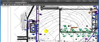
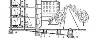
Residential building plan
The image shows a plan of a residential building that includes outlets of the sewer system, inputs of the heating system, cold and hot water supply with their reference to the angular coordination axes. In addition, it shows the diameters of the outlet and inlet pipelines, and also shows the sewerage wells KK-1, KK-2 and KK-3. According to current codes and standards, the plans must indicate pipe diameters, required elevations and dimensions of sloped pipes, sewer wells and network profiles.
Axonometric diagrams of sanitary systems
To perform axonometric diagrams of plumbing systems of buildings and structures, frontal isometry with a left-handed axis system is used. This makes it possible to use undistorted measurements on all axes. To designate axonometric diagrams of cold and hot water supply networks, system marks are used, placed directly above the diagrams. Full names of systems are indicated in the relevant specifications.
The figures below show axonometric diagrams of the building's hot and cold water supply pipeline systems. The schematic representation of the water supply system shows shut-off valves, pipe diameters, branches to the risers, places where water drains, as well as pipes for moving from one pipe diameter to another. The level of the first floor is marked using a horizontal line near the risers. In addition, the water supply diagram contains a designation that to arrange its input, pipes with a diameter of 50 millimeters should be used, and the elements should be connected using sockets.
Sections and sewerage diagrams
Diagrams of risers, as well as sections of sewer systems, show the location of risers and pipelines along branches and risers. Using the letters A and B on the section that depicts the outlet pipeline next to the KK-1 sewer well, the places where there are branches from the main pipe are indicated. In addition, this section shows data such as pipe diameters, installation locations for inspections, cleanings and other fittings, as well as slopes and lengths of sections.
The letters A and B, which are indicated for the sewer risers StK1-1...StK1-3 on the sections, indicate those places where the riser is connected to the main outlet into the sewer well KK-1. The place where the outlet from the sink is connected is indicated by the letter G. The siphon (hydraulic valve), located in front of the P/1 sink, is shown in the section along the outlet from the sink.
The diagrams also contain indications of those places where branches from risers should be laid along the floors to sanitary fixtures. The diagram of the risers of the K1 sewer system (Ø 100) contains instructions for the installation of inspections and the location of branches. To ensure ventilation of the risers, asbestos-cement pipes with a diameter of 150 millimeters are used. They are brought outside through the attic, and weathervanes are used to complete them.
Installation of internal sewerage networks
The internal domestic sewerage network consists of branch lines, risers, and outlets.
Discharge pipelines serve to drain wastewater from receivers through siphons to risers. All drainage lines are laid along the shortest distance with a slope towards the movement of wastewater. The diameters and slopes of branch lines, as a rule, are not calculated, but assigned.
For connecting drain pipes located under the ceiling of a room, in basements and technical undergrounds to risers, as well as for installing branches of drain pipes from bathtubs to one riser at the same level, it is allowed only with the use of oblique crosses. It is not allowed to connect the management of one outlet line of sanitary fixtures located in different apartments on the same floor, as well as the use of straight crosses when located in a horizontal plane. At the beginning of sections of outlet pipes, when there are three or more devices connected, and at turns with an angle of more than 30 degrees, cleaning devices should be installed to remove blockages.
Internal sewer networks can be laid: open along the walls. columns, on special supports in undergrounds, basements, corridors, technical floors, in special rooms intended for placing networks; hidden in furrows, wall niches, installation corridors, sanitary cabins, blocks, panels, under the floor (in channels or ground), sometimes in interfloor ceilings. Branch lines laid between floors must have a length of at least 10 m.
The risers are used to receive wastewater from drainage pipes on all floors. They are placed in areas where the largest number of devices are located and, if possible, closer to those devices from which the most contaminated waste flows (for example, a toilet). The number of risers is reduced if wastewater receivers are concentrated in a group above a group on floors.
The diameter of the sewer riser is selected depending on the estimated liquid flow rate and the largest diameter of the floor pipeline. If there is a toilet, the riser diameter is 100 mm.
If necessary, risers can be installed with indentations or horizontal sections with a slope. Connecting devices to horizontal sections is not allowed. Risers, like branch lines, are laid openly and hidden. The riser at the top ends with an exhaust pipe, which is at least 500 mm higher than the roof of the building. This is necessary for ventilation of the sewer network and prevents the hydraulic valves of wastewater receivers from breaking. At the bottom, the riser ends with a smooth transition into the outlet.
Outlets are designed to receive and drain wastewater from one or more risers into a yard or intra-block network. The risers are connected to the outlet at the beginning of it using two or one 135-degree bends and an oblique tee. Inspection wells are installed at the points where the outlets are connected to the external sewerage system. The length of the outlet from the riser or cleaning to the axis of the inspection well is determined depending on the diameter of the pipes.
Sewer outlets should be located on one side of the building perpendicular to the plane of the external walls from the side of the courtyard facade. For residential buildings with a technical underground or unused basements, it is permissible to install one or two end outlets. The arrangement of enlarged outlets is advisable in cases where a reduction in the length of the external network is achieved. They are not allowed to be installed in houses with operable basements, or in cases where the external sewer network runs along the building. Most often they arrange one release per entrance.
Issues join the external network “shelyga to shelyga. One or two outlets can be connected to each manhole. When determining the minimum depth of outlet from a building, they proceed from the condition of protecting pipes from destruction under the influence of loads and freezing. If the pipelines are deeply buried, when connecting the outlets to the external sewerage network, drops should be arranged: open in the form of concrete spillways, trays (with a drop height of up to 0.3 m). The difference should be arranged in the control well.
The outlet diameter must be no less than the diameter of the connected risers. For residential buildings, the outlet diameter is most often 100 mm.
To make it possible to clean pipes in domestic and industrial sewerage networks, installation of inspections or cleanings is provided. They are installed on risers if there are no indents on them, in the basement or first and upper floors, and if there are indents - above the indents. In residential buildings with a height of more than five floors, inspections are installed at least every three floors. The height from the floor to the center of the revision should be 1 m. Outlets are laid with a slope of at least 0.02 towards the yard sewer network.
Basic norms and rules for water supply installations
- All projects to provide the population with water supply must be developed with simultaneous coordination of all the nuances of the design and arrangement of the central sewerage system.
- It does not matter for what needs (household or industrial) a full supply of water is provided, a security zone must be organized around all water supply systems connected into one whole.
- Water supplied from the central water supply to support household activities, including for drinking needs, must comply with the state quality standard.
- Whereas, determining the quality of water for the needs of industrial premises should be regulated by the technological requirements of the enterprise.
- If water is intended to be used for gardening purposes (for watering plants), it must comply with sanitary, hygienic and agricultural technological standards.
- The design and installation of water supply and sewerage systems must be provided with the most modern technical solutions, complete mechanization of heavy and labor-intensive work, as well as full automation of technological processes.