Pulse transformers (IT) are a popular device in economic activity. Often installed in power supplies for household, computer, and special equipment. The pulse transformer is created by craftsmen with minimal experience in the field of radio engineering. What kind of device this is, as well as the principle of operation, will be discussed further.
Application area
The task of a pulse transformer is to protect an electrical device from short circuits, excessive increases in voltage, and heating of the housing. The stability of the power supplies is ensured by pulse transformers. Similar circuits are used in triode generators and magnetrons. The pulse generator is used when operating an inverter or a gas laser. These devices are installed in circuits as a differentiating transformer.
Electronic equipment is based on the transformer ability of pulse converters. When using a switching power supply, the operation of a color TV, a regular computer monitor, etc. is organized. In addition to providing the consumer with current of the required power and frequency, the transformer stabilizes the voltage value when the equipment is operating.
Video: How does a pulse transformer work?
The best materials for the device
IT design practice has shown that the best insulating materials that most fully satisfy the listed requirements are transformer oil, cable and transformer paper impregnated with transformer oil, electrical cardboard, fluoroplastic films alternating with layers of paper, and organic glass.
The load-bearing elements of the structure are paper-bakelite tubes and cylinders, prefabricated frames made of organic glass. Fluoroplastic films should be used only in IT applications where the temperature of the windings may exceed 95ºC.
The disadvantage of films is that a surface discharge easily develops along them in the longitudinal direction. Organic glass is widely used in IT due to its high insulating properties and the possibility of mechanical processing.
At voltages of 100 kV, insulation in the form of pure transformer oil is advisable. Unlike layered insulation, pure oil insulation is highly homogeneous in properties. This allows structures with a weakened edge effect to almost completely use the high electrical insulating properties of transformer oil.
Oil insulation has other important advantages. Transformer oil has good fluidity and can freely convect in the space between the windings and the MS. The consequence of this, as well as the high heat capacity of the oil, is good heat removal from the windings and MS.
The dielectric constant of transformer oil is approximately two times less than that of insulating paper and electrical cardboard. This makes it possible to reduce the capacitance of IT windings by the same amount. An important operational advantage of oil insulation is also its recoverability after short-term emergency conditions (single breakdown or sparking).
It is also easy to change the oil during routine maintenance. Thus, at high power and voltage, oil insulation is the most appropriate type of insulation in IT. However, its use is possible only in specially designed structures in which free circulation of oil is ensured and there are no paths for the spread of surface discharge.
Interesting material to familiarize yourself with: what a three-phase motor is and how it works.
Requirements for devices
Converters in power supplies have a number of characteristics. These are functional devices that have a certain overall power. They ensure the correct functioning of the elements in the circuit.
The pulse household transformer has reliability and a high overload threshold. The converter is resistant to mechanical and climatic influences. Therefore, the circuit of a switching power supply for televisions, computers, tablets. characterized by increased electrical stability.
The devices have small overall dimensions. The cost of the presented units depends on the area of application and labor costs for manufacturing. The difference between the presented transformers and other similar devices is their high reliability.
Principle of operation
When considering how a unit of the presented type works, you need to understand the differences between conventional power plants and IT devices. The winding of the transformer has different configurations. These are two coils connected by a magnetic drive. Depending on the number of turns of the primary and secondary windings, electricity with a given power is created at the output. For example, a transformer converts voltage 12 to 220 V.
Unipolar pulses are supplied to the primary circuit. The core remains in a state of permanent magnetization. On the primary winding, rectangular pulse signals are determined. The time interval between them is short. In this case, inductance differences appear. They are reflected by pulses on the secondary coil. This feature is the basis of the operating principles of such equipment.
Design (types) of pulse transformers
Depending on the shape of the core and the placement of coils on it, ITs are produced in the following designs:
- core;
Design of a rod pulse transformer - armored;
Design of an armored pulse transformer - toroidal (has no coils, the wire is wound on an insulated core);
Design of a toroidal pulse transformer - armored rod;
Design features of an armored rod pulse transformer
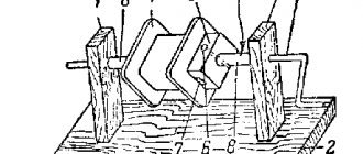
The figures indicate:
- A - magnetic circuit made of transformer steel grades made using cold or hot metal rolling technology (with the exception of the toroidal core, it is made of ferrite);
- B - coil made of insulating material
- C - wires creating inductive coupling.
Note that electrical steel contains few silicon additives, since it causes power loss from the effect of eddy currents on the magnetic circuit. In toroidal IT, the core can be made from rolled or ferrimagnetic steel.
The plates for the electromagnetic core set are selected in thickness depending on the frequency. As this parameter increases, it is necessary to install thinner plates.
Varieties
There are different types of pulse circuits of power equipment. The units differ primarily in the shape of their structure. Performance characteristics depend on this. The units are distinguished by the type of winding:
- Toroidal.
- Armored.
- Rod.
- Armored rod.
The cross-section of the core can be rectangular or round. The labeling must contain information about this fact. The type of windings is also distinguished. The coils are:
- Spiral.
- Cylindrical.
- Conical.
In the first case, the leakage inductance will be minimal. The presented type of converter is used for autotransformers. The winding is made of foil or awnings made of special material.
The cylindrical winding type is characterized by a low inductance dissipation rate. This is a simple, technologically advanced design.
Conical varieties significantly reduce inductance dissipation. The capacitance of the windings increases slightly. The insulation between the two layers of windings is proportional to the voltage between the primary turns. The thickness of the contours increases from beginning to end.
The presented equipment has different operational characteristics. These include overall power, voltage on the primary and secondary windings, weight and size. When specifying markings, the listed characteristics are taken into account.
How to check your device
After the IT is assembled, it is checked. There are plenty of methods on how to check a pulse transformer assembled by yourself or purchased. For testing, circuits are assembled using frequency generators, oscilloscopes, multimeters and other instruments that not only confirm the functionality of the IT.
They test it in various frequency ranges. In a pulse transformer, an open state of the secondary winding is not allowed; this mode belongs to the category of unsafe modes.
How to test a pulse transformer.
They must also have minimal leakage inductance, dynamic capacitance and resistance; be sufficiently strong mechanically.
It must be vibration-resistant and withstand the effects of significant electrodynamic forces that arise both in normal operation and, especially, during short circuits of the load circuit.
The requirements for high electrical strength and minimal leakage inductance are mutually contradictory. Since to increase the electrical strength it is necessary to increase the thickness of the insulation, while to reduce the leakage inductance it is necessary to reduce the thickness.
It will be interesting➡ How does a power transformer work and where is it used?
Advantages
Power supplies with a switching device have many advantages over analog devices. It is for this reason that the vast majority of them are manufactured according to the presented scheme.
Pulse type transformers have the following advantages:
- Light weight.
- Low price.
- Increased level of efficiency.
- Extended voltage range.
- Possibility to build in protection.
The structure is lighter due to the increased signal frequency. Capacitors decrease in volume. The scheme for straightening them is the simplest.
Comparing conventional and switching power supplies, it is clear that in the latter, energy losses are reduced. They are observed during transient processes. The efficiency can be 90-98%.
The smaller dimensions of the units reduce production costs. The material consumption of the final product is significantly reduced. The presented devices can be powered from current with different characteristics. Digital technologies, which are used to create small-sized models, make it possible to use special protective blocks in the design. They prevent short circuits and other emergency situations.
The only drawback of pulsed types of devices is the appearance of high-frequency interference. They have to be suppressed using various methods. Therefore, in some types of precision digital instruments such circuits are not used.
Types of materials
The presented equipment is made from various materials. When creating power supplies of the type presented, you will need to consider all possible options. The following materials are used:
- Electrical steel.
- Permalloy.
- Ferrite.
One of the best options is Alsifer. However, it is almost impossible to find it on the open market. Therefore, if you want to create the equipment yourself, it is not considered as a possible option.
Most often, electrical steel grades 3421-3425, 3405-3408 are used to create the core. Permalloy is known for its magnetically soft characteristics. This is an alloy that consists of nickel and iron. It is doped during processing.
For pulses whose interval is within a nanosecond, ferrite is used. This material has high resistivity.
High voltage constant voltage source
To create a high voltage (30...35 kV at a load current of up to 1 mA) to power an electroeffluvial chandelier (A.L. Chizhevsky’s chandelier), a DC power source is designed based on a specialized microcircuit of the K1182GGZ . The power supply consists of a mains voltage rectifier on a diode bridge VD1, a filter capacitor C1 and a high-voltage half-bridge oscillator on a DA1 chip of the K1182GGZ type. The DA1 chip, together with transformer T1, converts direct rectified mains voltage into high-frequency (30...50 kHz) pulsed voltage. The rectified mains voltage is supplied to the DA1 microcircuit, and the starting circuit R2, C2 starts the microcircuit's self-oscillator. Chains R3, SZ and R4, C4 set the frequency of the generator. Resistors R3 and R4 stabilize the duration of the half-cycles of the generated pulses. The output voltage is increased by winding L4 of the transformer and supplied to a voltage multiplier using diodes VD2 - VD7 and capacitors C7 - C12. The rectified voltage is supplied to the load through limiting resistor R5. Line filter capacitor C1 is designed for an operating voltage of 450 V (K50-29), C2 - of any type for a voltage of 30 V. Capacitors C5, C6 are selected within the range of 0.022...0.22 μF for a voltage of at least 250 V (K71-7, K73 -17). Multiplier capacitors C7 - C12 type KVI-3 for voltage 10 kV. It is possible to replace it with capacitors of types K15-4, K73-4, POV and others with an operating voltage of 10 kV or higher.
Rice. 4. Circuit diagram of a high voltage DC power supply.
High-voltage diodes VD2 - VD7 type KTs106G (KTs105D). Limiting resistor R5 type KEV-1. It can be replaced with three MLT-2 type resistors of 10 MOhm each.
A television line transformer, for example, TVS-110LA, is used as a transformer. The high-voltage winding is left, the rest are removed and new windings are placed in their place. Windings L1, L3 each contain 7 turns of 0.2 mm PEL wire, and winding L2 contains 90 turns of the same wire. It is recommended to include a chain of resistors R5, which limits the short circuit current, in the “negative” wire, which is connected to the chandelier. This wire must have high-voltage insulation.
Calculation
To create and wind transformer circuits yourself, you will need to calculate a pulse transformer. A special technique is used. First, a number of initial equipment characteristics are determined.
For example, a voltage of 300 V is set on the primary winding. The conversion frequency is 25 kHz. The core is made of a ferrite ring of size 31 (40x25x11). First you need to determine the cross-sectional area of the core:
P = (40-25)/2*11 = 82.5 mm².
Next, you can calculate the minimum number of turns:
Based on the data obtained, you can find the diameter of the wire cross-section that will be required to create the contours:
D = 78/181 = 0.43 mm.
The cross-sectional area in this case is 0.12 m². The maximum permissible current on the primary coil with such parameters should not exceed 0.6 A. Overall power can be determined using the following formula:
GM = 300 * 0.6 = 180 W.
Based on the obtained indicators, you can independently calculate the parameters of all components of the future device. Creating a transformer of this type will be a fascinating activity for a radio amateur.
Such a device is reliable and of high quality if all actions are followed correctly. The calculation is carried out for each scheme individually. When manufacturing such equipment, the secondary winding must be closed to the consumer load. Otherwise, the device will not be considered safe.
The operation of the transformer depends on the type of assembly, materials and other parameters. The quality of the circuit directly depends on the pulse unit. Therefore, high importance is given to calculations and the choice of materials.
Pulse transformer calculation
Let's consider how it is necessary to calculate IT. Note that the efficiency of the device is directly related to the accuracy of calculations. As an example, let's take a conventional converter circuit that uses a toroidal IT.
Converter circuit
First of all, we need to calculate the IT power level, for this we will use the formula: P = 1.3 x Pn.
The pH value displays how much power the load will consume. After this, we calculate the overall power (Rgb), it must be no less than the load power:
Parameters required for calculation:
- Sc – displays the cross-sectional area of the toroidal core;
- S0 is the area of its window (as expected, this and the previous value are shown in the figure);
Basic parameters of the toroidal core
- Vmax is the maximum peak of induction, it depends on what grade of ferromagnetic material is used (the reference value is taken from sources describing the characteristics of ferrite grades);
- f is a parameter characterizing the frequency with which the voltage is converted.
The next stage comes down to determining the number of turns in the primary winding Tr2:
(the result is rounded up)
The UI value is determined by the expression:
UI=U/2-Ue (U is the supply voltage to the converter; Ue is the voltage level supplied to the emitters of transistor elements V1 and V2).
Let's move on to calculating the maximum current passing through the primary winding of the IT:
The parameter η is equal to 0.8, this is the efficiency with which our converter must work.
The diameter of the wire used in the winding is calculated by the formula:
It remains to calculate the output winding of the IT, namely, the number of turns of the wire and its diameter:
If you have problems determining the basic parameters of IT, you can find thematic sites on the Internet that allow you to calculate any pulse transformers online.