Application area
After completing the welding process and cooling of the structure, it is necessary to evaluate the quality of the work and take action if deficiencies are found. Control begins with a visual inspection. If there are defects inside the seam, it is necessary to resort to other search methods. They must be classified as indestructible. Not everyone has the required accuracy. Radiography of welded joints is one of the non-destructive methods that provides accurate information about the condition inside the weld.
In flaw detection, the ability of X-rays to penetrate deep into a considerable distance is used due to the fact that their wavelength is short. When welding, situations may arise when the wrong mode is selected or foreign objects get into the weld pool. The formation of invisible defects will reduce the strength and reliability of the entire structure, which will be able to withstand less loads than planned.
Radiographic inspection of welds requires special equipment. The costs for it are reasonable in cases where the requirements for the characteristics of the connections are high. Another option is to control structures where other methods are difficult or impossible to use. An example is radiographic testing of welded joints of pipelines.
There are laboratories specializing in the inspection of welded joints, where all the necessary equipment is available and competent professionals work. If desired, you can carry out control yourself, having mastered the necessary skills. It is possible to rent the device for this purpose. Portable devices are very popular. They are used both for pipeline inspection and for profile and sheet connections. Stationary devices can be designed individually to solve specific problems.
Radiographic testing of welded joints of pipelines is carried out in accordance with the industry regulatory document OST 36-59, which specifies all the requirements for welding of these structures. It states, in particular, that all data on the control carried out is entered into a special journal and stored for 10 years after the start of operation of the facility.
Interpretation of radiographic images (Part 2).
Film quality
Successful interpretation of a radiographic image depends on the quality of the film used. If the quality of the film does not meet the minimum requirements of the applicable standards, it should be rejected and the radiographic examination repeated. The manufacturer's transcriber, in order to save money, may not be inclined to reject images that do not meet minimum quality standards. Therefore, the third party reviewer must take extreme care to correctly evaluate the quality of the radiographic images before approving any report, otherwise such images may be challenged in the event of legal disputes. When assessing the quality of a film, there are a few things to consider, which we'll discuss in more detail below.
Parts identification
All radiographic images must be indelibly uniquely marked with comprehensive information in a manner that allows them to be correlated with details that will be the subject of a radiographic study in the future. It will be helpful to include information such as the date of testing and heat treatment or the repair status of the part. The markings may be applied by the X-ray machine itself, but there is no reason not to apply the markings by any other suitable means. The approved procedure shall describe a uniform method for marking radiographic images.
Designation of areas
Image identification has two functions: it identifies the specific radiographic examination area on a part and serves as evidence that the part has been fully tested using an approved method. Wherever possible, markings should include information about the area being surveyed. Equipment such as pressure vessels are typically permanently stamped with full radiographic information. The approved procedure shall describe the uniform method used to apply the site designation.
Film Density
It is important that the film density is within the specified range, because... Low density film will also have low image contrast. EN/ISO 17636-1 provides film density requirements: for Class A photographs – 2.0, for Class B photographs – 2.3. ASME V paragraph 2 requirement is a minimum of 1.8 for the X-ray method and 2 for the gamma ray method. In most cases (including EN/ISO 17636-1 and ASME V paragraph 2), minimum film densities apply to the specific area of interest (test area) in the image. In radiography of weld joints, for example, film density is measured in the area of welded metal between designated areas (which define the beginning and end of the area being diagnosed).
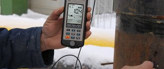
Density is usually assessed using a measuring instrument known as a densitometer. A technician who accepts an image that does not meet the minimum density requirements will be held liable in the event of litigation resulting from failure of the relevant equipment.
According to the requirements of ASME V paragraph 2, the film density in the area of \u200b\u200bthe test area should not vary more than minus 15 or plus 30% of the value measured on the sensitivity standard. If necessary, it is permitted to use additional sensitivity standards in order to meet this requirement if we are talking about any special areas.
Upper limits on film density are sometimes specified. In ASMEV paragraph 2, for example, the upper limit is given as 4, or the upper limit is specified in the customer specification.
Sensitivity to radiographic radiation
Radiographic sensitivity does not directly relate to the minimum size of a detectable defect. However, an image that meets the requirements of a standard applicable to radiographic sensitivity is more likely to provide good defect sensitivity than an image that does not meet such standard requirements.
The sensitivity of a radiographic image depends on the parameters chosen to take it. If any of the relevant parameters are changed, the sensitivity will be affected. Therefore, it is necessary to use sensitivity standards in order to confirm that an image of appropriate quality has been obtained. This does not apply to cases with the technique of taking panoramic photographs, where each photograph must contain at least one sensitivity standard.
False defects and other unwanted images
False defects on radiographic film are any images whose origin is not related to the object being examined.
False defects can be caused by mechanical or chemical damage to the film, as well as damaged or dirty intensifying screens. Sometimes false defects on radiographic film can be formed due to contaminants on the inner surface of the tube. Such images, unless specifically identified as false, can also prevent the images from being correctly deciphered.
When radiography is performed on a commercial basis (mass production), it is impossible to ensure that every film is free of false defects. The presence of false defects becomes a significant factor when it is impossible to establish their fictitiousness or when they interfere with the decoding of the film. These two factors are more subjective, but if in doubt, the transcriptionist should request repeated studies. A list of possible false defects is given in the next section.
Interpretation of radiographic images
There are three types of images found on radiographic film that can occur due to:
- False defects
- Irregularities in the surface of the object under study
- Inhomogeneities of the alloy structure of the object under study
Each image within the diagnostic area should be checked for the possible presence of any of the three points above.
Rejection of the test object is not allowed due to the inability to decipher the area being diagnosed or due to false defects located outside the area being diagnosed. The following sections describe the different types of images that you may encounter during your work. The ability to successfully identify all defects and false indications on a radiographic image is a skill that can only be acquired through experience and time. Share this material:
Principle of operation
Radiography is based on the ability of rays to penetrate into materials, including metals. This ability decreases with increasing metal density and increases with decreasing density. Since the density becomes lower in places with voids and cracks, this is immediately recorded by the device. If there are no defects, the metal structure remains consistently dense, and X-rays will be absorbed by the material. The higher the density, the higher the degree of absorption will be.
The main element of the apparatus for fluoroscopy of welds is the emitter, which is an X-ray tube. Its function is to generate rays and release them. Structurally, the emitter is a vacuum vessel. It contains an anode and a cathode, between which an electric potential is formed. When electrons are strongly accelerated, X-rays appear and the direction of their exit is set.
The rays passing through the metal fall on a special photosensitive film. An imprint remains on it, by which one can judge what is inside the material. The full picture will be shown by deciphering x-ray images of welded joints. If you want or need to receive information constantly, scintillators are used. This makes it possible to display the image on the monitor.
It is possible to take photographs by obtaining an x-ray. The radiograph will show a negative image of the joint. If there are inclusions or, conversely, voids, their outlines will appear in a different color. The resulting radiograph should be compared with a typical radiograph for this type of welded parts. The method allows you to accurately and quickly assess the condition of the weld.
Pictures of welds, training and photos
We invite you to familiarize yourself with our template photos. Below you will find a detailed description with reasons for each defect. Including those with Tig welding defects (argon welding, aluminum welding)
internal concavity
Image 1 of 13
Understanding welds in photographs occurs in three main stages:
- Detection
- Interpretation
- Grade
For all these steps, it is necessary that your specialist has a “Universal Modulator” mind - because all these steps use the radiologist’s mind. In this case, MIND is the ability to resolve a spatial picture using imagination.
A person's ability to detect irregularities in X-ray images also depends on the lighting conditions at the viewing location and the level of experience in recognizing various features of the image. (more about X-rays)
This article is written to help better understand the types of defects found in welds and how they appear in weld scans and photographs.
Tears in weld images
Breaks are interruptions in the typical structure of a material. These interruptions can occur in the metal structure, welding material, or heat-affected zones. Breaks that do not meet the requirements and tolerances used in the part are called defects.
Preparation for control
Before starting the process, preparatory operations should be carried out. The parts of the future connection are carefully inspected. If there are contaminants and slag on them, they must be thoroughly cleaned and degreased with solvent or alcohol. This is done so that external defects during transillumination do not distort the final result.
Films are loaded into appropriate cassettes. All connections are divided into separate intervals and labeled. This is done so that you can accurately determine which image relates to a specific area of the welded seam. Cassettes and films are marked in the same order. If the seam is long, selective X-ray inspection of the welds is possible.
It is also necessary to prepare equipment intended for radiography of welds. First you need to select a suitable radiation source. The criteria are sensitivity, metal thickness and density, configuration of parts, required performance. For example, for radiographic testing of welded joints, where large defects are possible, isotopes with high energy are suitable. This will ensure a short transillumination time. The choice of film is determined by the thickness of the metal and its density. Optimal modes are set on the devices.
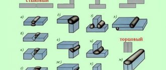
Separation of types of welded joints based on inspection results
Based on the results of the data obtained in the images, each seam is assigned one or another class depending on the size of the defect. According to regulatory requirements, classification is based on pore sizes, as well as oxide, slag and tungsten inclusions. For example, with a product thickness of up to 3 mm, it is assumed that welded joints are divided into types depending on the total length of the defect - from 3 to 10 mm. If we are talking about parts with a thickness of 200-400 mm, then the classification range for the same parameter will vary from 10 to 90 mm. Again, if the length of the radiogram is less than 100 mm, then the calculated data on the size of individual inclusions and pores decreases in proportion to the size of the image. In this case, the length of the accumulations in accordance with the requirements should not exceed 1.5 relative to the maximum permissible lengths for individual pores and discontinuities.
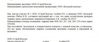
After processing the radiographic inspection materials, a special report is drawn up, which indicates data on the product and the defects it contains. First of all, the characteristics of a part or structure are described, indicating pre-designated standards and marked zones. The radiographic inspection report of welded joints may include data on capacity, product thickness and other technical and structural indicators. As for information on defects, the entire list of information obtained as a result of deciphering radiographic images is entered in special columns.
Process methodology
Radiography of welds goes through several stages:
- Select a radiation source.
- Select the appropriate type of film.
- Set the equipment to optimal modes.
- Place the device inside or outside the product and turn it on.
- Start X-raying the weld.
- Take out the film and develop it.
- Perform decryption.
- Record the results in a journal in the prescribed form.
The selected cassette is secured to the product. To obtain good image sharpness and determine the reliable size of the defect, a sensitivity standard should be set on the device. The standard must be made of a material whose characteristics are close to the characteristics of the metal being welded.
GOST 7512 specifies three preferred types of standards used for x-raying welds:
- Grooved . A plate having six grooves. They have the same width, but different depths.
- Wire . Has seven wires.
- Lamellar . A plate having holes of the required shapes and sizes.
The items being tested can be placed in relation to the apparatus in two ways. If they are small and can fit indoors, the connections are placed inside the stationary apparatus. During on-site inspection, compact models of equipment are used and installed on the product.
To carry out radiographic inspection of welded joints, the seam should be placed strictly between the emitter and the photosensitive film. After turning on the emitter, X-rays will begin to pass through the metal and hit the film. In a few seconds the photo will be ready. The device is turned off. The cassette with the film is removed and given for processing and decoding. Once it is clear that the result has been obtained, the device can be removed from the product or removed from it. Otherwise, it is necessary to re-check.
Decoding
Interpretation of radiographs is carried out in a shaded room using a negatoscope. It is a device whose purpose is to view radiographic images, including radiographs, through transmission. The negatoscope provides the ability to adjust the brightness of the lighting. If its value is too high, small defects may be missed.
After decoding, a conclusion is drawn up. Before resorting to this method, it is necessary to find out what weld defects are detected using radiographic testing. These include:
- undercuts;
- lack of penetration;
- cracks;
- pores;
- foreign inclusions;
- slags
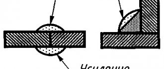
In addition, it is possible to evaluate the amount of concavity and convexity in places where visual inspection is not possible. Abbreviations are used when writing results. So, “T” means a crack, “N” is a lack of penetration, “P” is a pore, “W” is slag, “V” is the inclusion of tungsten, Pdr is an undercut. The size of the defect is indicated next to the letters. The nature of the distribution is also taken into account.
On this basis, shortcomings are divided into groups:
- Separate.
- Chains . There are more than three defects on one line.
- Clusters . Location of at least three defects in one place.
The size of the defect is indicated in millimeters.
Safety
For all its advantages, the method is potentially hazardous to health. Therefore, it is necessary to shield the device. The controller should not be unnecessarily in the irradiation area. Access there to unauthorized persons should be prohibited. To do this, warning signs should be posted.
When working indoors, its walls must be covered with shielding plates. The controller must be provided with a set of protective clothing. Before starting the process, it is necessary to check the serviceability of the equipment.