The oxygen in the cylinder used in gas-acetylene welding is under a pressure of 135...150 atmospheres, so the gas pressure should be significantly reduced before work. This role is performed by the oxygen reducer. This device not only reduces the oxygen flow, but also ensures constant operating pressure throughout the entire welding process.
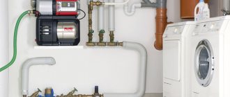
Design and principle of operation of an oxygen reducer
The direct purpose of the reducer is to ensure a constant ratio between the inlet gas pressure from the cylinder and the output, working, which enters the welding torch.
The simplest oxygen reducer consists of the following elements:
- Locking spring.
- Inlet valve.
- Pusher.
- Membranes.
- Pressure disk.
- Pressure spring.
The inlet valve is the most critical component of the oxygen reducer. He is constantly under the influence of two forces acting in opposite directions. One of them is created by the initial pressure of oxygen, which is in the cylinder. This pressure tends to push the locking spring upward and allow gas flow to flow to the pusher. However, the second pressure from the membrane prevents this. As a result, the reduced pressure chamber always maintains a balance of forces that are created by the shut-off spring and the membrane, which is ensured by the adjustment of the gearbox. In principle, the device is similar to an acetylene gearbox.
The oxygen reducer operates in the following sequence. When you try to lift the shut-off valve plate up, the force transmitted to the membrane from the pressure spring tends to prevent this. If the operating oxygen pressure is reduced, the pressure spring begins to move upward and move the membrane in the same direction. The pusher overcomes the resistance of the locking spring and opens the inlet for the passage of gas contained in the oxygen cylinder. Oxygen consumption increases accordingly. And vice versa, as the working pressure increases, it acts on the pusher, which moves down and blocks part of the inlet hole. With a properly adjusted oxygen reducer, dynamic equality is constantly maintained between these two processes.
Adjustment of the oxygen reducer consists in the fact that the tension force of the lower pressure spring can be changed. In most cases, a screw with a fine thread pitch is used for this. If this screw is removed, the spring tension weakens and the operating oxygen pressure decreases. As the screw is screwed in, the pressure increases.
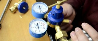
The set of conventional gearboxes that are required to perform gas welding work includes two pressure gauges. One of them controls the pressure at the inlet to the reducer, and the second controls the pressure after reduction.
Structurally, oxygen reducers are produced in two versions - direct and reverse. In direct-pressure reducers, the initial oxygen that comes from the cylinder tends to open the valve, and in reverse-acting reducers, it tends to close it by pressing the pusher against the seat.
The dependence of the oxygen pressure in the cylinder, which is equipped with a reducer, changes according to a parabolic dependence: it is maximum in the initial period, and over time it decreases to the level of the operating pressure of the welding process (in this case, the reducer is actually no longer required). In practice, a reverse-acting reducer turns out to be more efficient, since it can ensure constant operating pressure values (regardless of the initial oxygen pressure in the cylinder) until the cylinder is completely emptied. At the same time, the direct-acting oxygen reducer reduces the working pressure when the cylinder is half empty, since the ratio of forces acting on the pusher is disrupted. Therefore, such devices require constant adjustment by the welder.
Adjustment
The tension of the main spring is adjusted using an adjusting screw, depending on the initial gas pressure in the cylinder. The control spring lowers with the diaphragm, opening an opening for carbon dioxide to pass under reduced pressure to the shut-off valve. From there, the gas flow moves through the hose to the burner. The membrane of the carbon dioxide reducer is made of oil-resistant rubber and ensures its precise positioning relative to the outlet. As the gas pressure in the cylinder decreases over time, the upper control spring can drop, changing the flow area of the inlet valve. The carbon dioxide reducer also allows manual control of the gas flow; to do this, simply unscrew/screw in the adjusting screw, depending on the current readings of the pressure gauges.
The constant pressure in the reducer chamber is ensured due to the fact that when the gas pressure coming from the cylinder decreases, the membrane moves upward, compressing the return (upper) spring, and when the pressure increases, it moves down. The outlet pressure remains stable due to a corresponding change in the flow area of the shut-off valve.
To ensure the resistance of the membrane against sudden excess of gas pressure (which can cause the membrane to rupture), carbon dioxide reducers are equipped with a safety valve. It is triggered when the inlet fitting for some reason loses its seal and begins to let an increased volume of carbon dioxide from the cylinder.
Types and characteristics. Gearbox BKO 50-4 and BKO 50-5
According to their technical parameters, reducers for oxygen cylinders are divided into two groups - ramp and station. Ramp gearboxes are characterized by increased throughput - from 100...120 m 3 /h, and therefore are used to power a group of welding stations, or for welding work with large volumes. Station reducers are for individual purposes; they provide oxygen consumption in quantities of 5...25 m 3 /h (lower values correspond to lower final gas pressures).
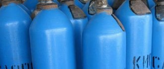
The housings of gas reducers are of the same type in appearance, so during manufacture they are painted in certain colors (for oxygen reducers this is blue).
GOST 13861 provides for the following versions of oxygen reducers:
- Cylinder type BKO, BKD and BPO.
- Network, such as SKO, SAO, SPO, SMO.
- Universal (U).
- Ramp (RKZ, RAD, RPD).
- Central (CDC).
The main technical characteristics of an oxygen reducer are its throughput and the operating pressure of the gas in the cylinder. For example, an oxygen reducer type BKO 50-4 means that the unit is designed to be connected to an oxygen cylinder, is single-stage, and is designed for a throughput of up to 50 m³/h at a gas operating pressure of 4 atmospheres. Accordingly, for the BKO 50-5 oxygen reducer the permissible operating pressure is 5 atmospheres. It is the BKO type gearboxes that are most often used for individual gas welding stations.
Additional operational features of oxygen reducers are:
- Number of reduction stages. Single-stage devices are produced, in which the pressure regulator is either a spring or another unit, and two-stage ones, where pressure regulation occurs gradually, using intermediate pneumatic chambers. Two-stage gearboxes provide more reliable operation of the welding station at low temperatures, are more stable in their characteristics, but are characterized by structural complexity and, therefore, increased price;
- Connection method. A union nut is used rather than a clamp, since the explosiveness of oxygen requires special requirements for tightness;
- Climatic performance. The requirement for reliable operation of the current regulator especially increases when gas welding is carried out not only at low temperatures, but also with large volumes. At high flow rates, the oxygen pressure quickly decreases, which is accompanied by an increase in the volume of gas remaining in the cylinder. This physical process accelerates the cooling of the gas and the reducer, as a result of which the device may become inoperable.
Types of pressure gauges.
There are such types of these devices:
- technical (measure excess and vacuum pressure in non-aggressive media, liquids that are not catalyzed, as well as in gases and vapors);
- electronic - not only measure pressure like technical ones, but can also regulate it due to the presence of a contact mechanism;
- self-recording - additionally equipped with a mechanism for recording pressure gauge operating data and displaying them on paper in the form of a graph;
- railway (measure the pressure of gaseous and liquid media that are non-aggressive to copper alloys and installed in railway rolling stock);
- vibration-resistant – work in vibration conditions;
- shipboard - measure excess pressure of steam, gas and non-aggressive non-crystallizing liquids, such as sea water or diesel fuel;
- reference - designed for testing pressure gauges in operation.
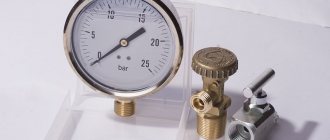
The pressure gauge for the oxygen reducer is a technical one - for special purposes.
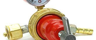
This device is used to reduce the gas pressure, in our case oxygen, to working pressure and maintain it at a certain level. Many pressure gauge manufacturers paint them blue. Which means that this model is designed to work specifically with oxygen.
Based on a number of characteristics, oxygen reducers on which pressure gauges are installed are divided into:
- direct action;
- reverse action;
- operating gas pressure;
- bandwidth.
Rules for safe operation
Considering the explosion and fire hazard of oxygen, such products, in accordance with GOST 12.2.008-75, must be periodically subjected to thorough routine maintenance. In relation to oxygen reducers of type BKO 50-4 and BKO 50-5, maintenance rules include:
- Checking the movement of the adjusting screw/flywheel from one extreme position to another: it should be smooth and without jamming.
- The connecting elements must not have external mechanical damage - cracks, scratches, and also be cleaned of oil, grease and dirt.
- Periodic checking of pressure gauges should not be less than once a year. The criterion for the need for verification is considered to be increased inertia of the instrument needle.
- Parts that do not meet the operating conditions of oxygen reducers cannot be used as sealing elements - gaskets, nipples, etc.
- Before each use, the tightness of the connections is checked (using a pressure gauge); leakage of oxygen from the cylinder is unacceptable.
- When an oxygen cylinder is connected to the reducer, it is prohibited to make any adjustments.
- According to labor safety rules, it is necessary to provide for the installation of safety devices between the reducer for the oxygen cylinder and the rest of the gas welding equipment, including those for extinguishing the flame. These can be check valves designed for the pressure in the cylinder, as well as safety valves.
The price of an oxygen reducer is determined by its design and operational capabilities. For single-stage gearboxes, the price ranges from 1800...2000 rubles. (BKO 50-4) and 1100...1200 rub. (BKO 50-5). Two-stage devices (for example, BKD-25 or Multi-Stage RG S2 O2 made in Czech) are much more expensive - 11,000...12,000 rubles.
— Search by diary
— Subscription by e-mail
— Statistics
Saturday, January 28, 2021 15:07 + to quote book
Operation of the gearbox.
Before connecting the oxygen reducer, you must carefully check whether there are any traces of oil, etc. on the fitting and union nut. If traces of fatty substances are found, the reducer must be washed in some solvent (for example, aviation gasoline).
Next, you need to check the serviceability of the thread of the union nut, clean it from dirt and dust, and also check the presence and serviceability of the fiber (for oxygen gearboxes) or leather (for acetylene gearboxes) gasket, on which the tightness of the connection between the gearbox and the valve depends.
After blowing out the oxygen valve of the cylinder or line to remove dirt or chips from them that could get into the reducer and damage its valve, the union nut of the oxygen reducer is screwed to the valve fitting and secured with a wrench.
In the same way, it is necessary to purge the valve of the acetylene cylinder before attaching the acetylene reducer to it.
Before releasing gas into the reducer, its adjusting screw must be turned out until the pressure spring is completely weakened, so that when opening the cylinder valve, the reducer cannot be damaged. The shut-off valve on the gearbox must be open. A hose is attached to the hose nipple of the gearbox and secured firmly with clamps or soft wire.
To release gas into the reducer, you must smoothly open the cylinder valve half a turn of the handwheel. If no abnormalities are observed, then the cylinder valve should be opened all the way and by rotating the pressure control screw of the gearbox clockwise, set the required operating pressure using the pressure gauge. The operating oxygen pressure is set when the cutter valve is open.
When, due to the presence of oil or a sudden release of oxygen, a flash or strong heating of the gearbox occurs, it is necessary to quickly close the cylinder valve, and remove the gearbox and send it for repair.
After establishing the operating pressure, it is necessary to check whether there are gas leaks at the joints, along the threads of pressure gauges, etc. Gas leaks are dangerous, since acetylene and other flammable gases form explosive mixtures with air.
After checking, the torch is ignited and the flame is adjusted.
During operation, it is necessary to ensure that there are no leaks, freezing, etc. in the gearbox.
When you stop working for 2-3 minutes. Only the valves on the cutter can be closed. If work stops for 10-15 minutes, then in addition to the cutter valves, close the gearbox shut-off valve without changing the position of the control screw. During breaks in work for more than 10-15 minutes. You should additionally loosen the pressure spring by unscrewing the adjusting screw.
During long breaks and at the end of work, the valve of the cylinder or line is closed and the gas remaining in the reducer is completely released. Then, by turning the adjusting screw counterclockwise, the pressure spring is weakened.
Design features and maintenance
There are 2 types of gases used in industry and everyday life:
- inert;
- flammable.
The adapters on them are fundamentally different, so as not to confuse them. For inert gas cylinders, the connection between the reducer and the cylinder is made with a right-handed, standard thread. Oxygen, propane, carbon dioxide, methane and other flammable gases are connected to the reducer by screwing it into a hole with a left-hand thread - counterclockwise.
Multi-directional threads eliminate the possibility of filling the container with the wrong type of gas and using the cylinder for purposes other than its intended purpose.
Gearboxes have a membrane inside that wears out. The gearbox must be tested every 5 years. In this case, the membrane is replaced with a new one. In reducers for composite cylinders - made according to European standards, the membrane is designed to operate for at least 10 years, but the equipment must be tested after 5 years.
There is a marking on the top of the case indicating the year of manufacture of the unit and the first verification. During the subsequent test, the next date is entered.
The gearbox must be lubricated regularly and checked for leaks. If necessary, the gaskets must be changed.
Instructor, college teacher at the Donmet plant P.V. Sarkizov: There is an opinion among amateurs that a gearbox with a rotameter allows you to use gas economically. In practice, the devices differ only in their readings. The second pressure gauge on the reducer shows gas flow per minute. This value is inherent in the welding modes. The rotameter shows the actual pressure in the working chamber at the moment. To set operating parameters, you need to recalculate the rotameter readings using a coefficient or use a conversion table.
Gearboxes with 2 rotameters are designed for welding refractory metals and with high heat transfer. A welding torch is connected to the first, and a nozzle for heating the back side of the seam is connected to the second. You cannot connect 2 devices."
Purpose of the oxygen reducer
Oxygen is an integral component of the so-called gas welding or metal cutting. It is delivered to the work site in cylinders made of steel and painted blue.
To ensure the supply of oxygen under operating pressure, reducers are used. In accordance with GOST 13861-89, these devices are marked as follows - BKO, SKO, RKO. The first abbreviation means that the reducer is used for installation on oxygen cylinders, single-stage (D - two-stage). The second is a network Product, and the third is a ramp Product.
Several types of these devices are produced - BKO 25 and BKO 50. The first type provides oxygen supply up to 25 cubic meters per hour, the second 50. The maximum operating pressure parameter of the first model is 0.8 MPa, for the second 1.25 MPa.
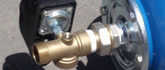
A union nut is used to connect the oxygen reducing device.
The gearbox uses the following principles in its operation:
- The gas passes through the filter and is supplied to the high pressure chamber. Rotation of the regulator transfers the force of the installed spring through the disk, diaphragm and pusher directly to the valve. It is he who regulates the flow of oxygen into the working volume.
- The unit in which the pressure changes occurs is a separate assembly unit consisting of a seat, a valve with a spring and an EF-5 filtration device. To increase safety, a valve is mounted on the device body, designed to release gas when a critical pressure level in the working chamber is reached from 16.5 to 25 kgf per square centimeter.
Oxygen reducer pressure gauge
As part of the oxygen reducer, pressure gauges are used, one shows the pressure value in the cylinder (network), and the second shows its output parameter. The oxygen mixture is supplied to the welding zone through a hose with a diameter of 6 mm or more. The hose is connected to the fitting, and a cutter or burner is installed at the other end.
DIY gearbox repair
Repair of a gearbox using the example of oxygen BKO-50. Perform only with uncontaminated hands.
First of all, pay attention to the condition of the seal on the gas inlet fitting and the presence of the EF-2 filter element, which protects the reduction unit from debris, scale, and all kinds of small particles.
Before installing the filter (place the narrow part towards the gas flow), remove the inlet fitting and sealing gasket. The latter must be made of materials suitable for working in contact with oxygen (polyamide, fluoroplastic, paronite). There should be no delaminations or cracks on its surfaces. Tighten the breather. The EF-2 filter element should not play after tightening.
Next, you need to connect the gearbox to a source of compressed air or nitrogen. It is strictly not recommended to test with other gases.
Pay attention to the pressure gauges, they must be in good working order, check that the arrow pointing to the readings is at zero. The instruments must be turned towards the worker so that he can read information about the readings from them. Polyamide gaskets are used to install pressure gauges. Apply minimum pressure to the input (for each gearbox it is different, for BKO - 50 - 30 atm.).
In this case, the problem of gas bleeding may arise due to the lack of tightness of the connection between the reducing unit and the valve when the set screw is unscrewed. To resolve this problem, it is necessary to replace the reducing unit. To do this, you will need a special key that can be used to unscrew the gearbox housing.
Next, remove the pusher and unscrew the seat using a spanner. Pay attention to the presence of nicks on the shut-off part of the valve. Remove the reducing valve (check it for damage), then the spring (there should be no signs of corrosion or peeling of the coating on it).
Replace defective parts. Assemble the gearbox.
The check can be carried out with incomplete assembly, after tightening the valve seat with a spanner. The tightness will be checked by applying a soap solution. If no bubbles appear, assembly can continue.
Checking the serviceability of a fully assembled gearbox is carried out using a crane with consumables. puck. For BKO-50, the consumable washer has a diameter of 2.8 mm. With the flow washer valve fully open, you need to set the working pressure to 12.5 atm, then close the washer valve and monitor the increase in pressure on the low pressure gauge (no more than 3.75 kg from the maximum working pressure).
Checking the safety valve
Fuse the valve should open at a pressure of 16.5 kg to 25 kg. Check if this is true: apply a soap solution to the valve hole, and close the second hole with your finger. If the valve does not open, it needs to be adjusted. If the pressure needs to be increased, the valve plug is screwed in; if you need to make it open earlier, the valve plug is unscrewed. After adjusting the safety valve, the plug is cored and a mark is made with paint so that the setting is not lost.
The gearbox is in good condition and you can continue using it.
Types of oxygen reducers
Gearboxes can be divided into two large classes – ramp and stationary. The former are distinguished by high gas throughput, reaching 120 cubic meters per hour. That is why they are installed to supply oxygen to combined welding stations. The second oxygen reducers are intended for personal use. They guarantee gas consumption ranging from 5 to 25 cubic meters per hour. It should be remembered that in appearance oxygen reducers are similar to each other.
GOST 13861-89 defines the following types of products for reducing oxygen pressure:
- On the cylinders - BKO, BKD and BPO.
- In the backbone network - SKO, SAO, SPO, SMO.
- Universal - U.
- Ramp ones - RKZ, RAD, RPD.
- Central action - CDC.
The key parameters of an oxygen reducing device are the ability to pass a certain volume of gas per unit of time and maintain a given gas pressure in the container.
Oxygen reducer BKO 50-4
Thus, BKO 50-4 provides a gas supply of 50 cubic meters per hour and with a pressure of 4 atm. BKO 50 – 12, at the same flow rate, maintains a pressure of 12 atm. By the way, devices of these models are most often used to equip working gas welding stations.
Oxygen reducer RKZ 500-2 (collection diagram)
RKZ 500-2 (ramp oxygen reducer) is designed for simultaneous supply of gas to several gas welding stations. These devices operate in a temperature range from -5 to +50 degrees Celsius. By the way, experts recommend equipping oxygen devices of this class with additional filters.
Gearbox with rotameter
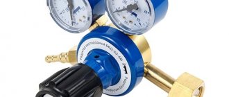
Increased functionality (compared to gearboxes) is provided by carbon dioxide flow regulators with a rotameter. Unlike traditional pressure gauges, for which the flow rate must be set depending on the current pressure, rotameters show the flow rate immediately. Universal flow regulators, which include rotameters, greatly facilitate the work of the welder and allow optimizing the consumption of carbon dioxide during welding. The issue price is from 1800 to 2000 rubles. The technical characteristics of the regulators - flow, pressure, temperature range of use - must correspond to the required welding modes.
Regulators differ from conventional gearboxes in the following ways:
If in gearboxes the outlet fitting is connected directly to the main line, then the regulator is equipped with a special damper that throttles the flow of CO2, depending on the gas pressure in the cylinder. The hole in the throttle is calibrated, which increases the accuracy of flow adjustment. Therefore, most models of regulators are equipped with one pressure gauge, the readings of which are set not in pressure units, but in flow units. Some regulators provide built-in electric gas heating. This allows welding to be carried out at subzero temperatures, and increases the accuracy of determining the actual gas flow rate (in gearboxes, the flow rate, as a rule, cannot be adjusted to a different value). Regulators for semi-automatic machines can be installed not only on a cylinder with liquefied carbon dioxide, but also on so-called mixed cylinders, which contain a mixture of carbon dioxide with an inert gas, in particular argon (in a ratio of 1:4).
When choosing the standard size of a carbon dioxide gearbox, pay attention to such design features as the design of the adjusting screw and the presence of a captive thread on it (otherwise you can unscrew the seat), as well as the presence of an additional shut-off valve
The quality of the gas is also important: food-grade carbon dioxide has low humidity, so the inside of the cylinder does not rust
Design and principle of operation of an oxygen reducer
Reverse-acting devices have become widespread in practice. The reason for this is their minimal dimensions and the design simplicity of the product.
Oxygen reducer design
The body of this device contains two consecutive vessels. The first is a high-pressure container, it receives gas from a cylinder or from a gas supply line. A valve is mounted between the containers, controlled by two springs acting on the membrane. The valve stroke directly depends on the force developed by these springs.
The spring installed in the first chamber is adjusted using an adjusting screw. It adjusts the stroke of the control valve. To close it, just turn the screw all the way.
The low pressure chamber is directly connected to the burner (cutter), that is, the pressure level in the container determines the level of gas pressure on the burner (cutter). If the gas flow exceeds the volume supplied, the pressure in the first tank will drop. In this case, the spring will press on the membrane with great force and as a result the valve will open to a greater extent and the volume of gas supplied will increase. If the flow rate is reduced, the spring will return the valve to its place. Thus, automated regulation of operating parameters in the reduction device occurs.
Operating principle of the gearbox
The reverse-action oxygen reducer, which is more reliable in operation, has become widely used, as it is more compact and simpler in design. The reducer has two chambers - one with high oxygen pressure from a cylinder or line and a working chamber with low pressure. The oxygen pressure in the high-pressure chamber is equal to the oxygen pressure in the cylinder, since the chamber is directly connected to the cylinder. Between the chambers there is a valve, which, through a membrane, is acted upon by two springs, the opening of which depends on the compression ratio of these springs.
The spring tension of the low pressure chamber is adjusted by a screw, accordingly adjusting the degree of openness of the valve and thereby changing the pressure in the second chamber, with low pressure. To close the valve, it is necessary to loosen the spring, that is, unscrew the screw. The low pressure chamber is connected to the burner through a gas valve and hoses, and the gas pressure in the burner is equal to the pressure in the low pressure working chamber. If, at some position of the adjusting screw, the oxygen flow and its supply are equal, then the operating pressure always does not change.
When oxygen consumption is greater than its supply, the pressure in the low-pressure working chamber will decrease. In this case, the pressure spring will put pressure on the diaphragm and deform it, which will force the valve to open slightly more and the flow of oxygen into the working chamber will increase. As the oxygen flow rate decreases, the pressure in this chamber will increase, which causes compression of the spring and deformation of the diaphragm in the opposite direction. This causes the valve to close the passage hole and the flow of gas decreases. This ensures automatic maintenance of oxygen pressure at the outlet of the reducer.
There are two pressure gauges installed on the oxygen reducer: high and low pressure. The oxygen pressure gauge in the cylinder or line is monitored using a high pressure gauge, and the operating pressure of oxygen supplied to the burner is regulated using a low pressure gauge.
Oxygen reducer characteristics and design features
In addition to the key parameters in the form of flow and pressure, gearboxes have the following additional characteristics:
Oxygen reducer characteristics
- Number of pressure reduction stages. Manufacturers produce devices with one or two stages of regulation. In the first, the main role is played by the spring. In models with two stages, adjustment is carried out using intermediate air chambers. These products guarantee the operation of the gas welding workplace in conditions where the temperature is below zero. In addition, these reducers guarantee a stable gas supply. But they differ in design complexity and, accordingly, cost.
- All oxygen reducers are connected to the gas source using a union nut. Clamps and other fastening devices must not be used. This is caused primarily by the explosive properties of oxygen, which require high-quality sealing of the connection.
- Another parameter of oxygen reducing devices is the climatic design. This indicator is important. The fact is that a drop in pressure leads to an increase in its volume. This leads to overcooling of the reducer and gas, which can lead to damage to the device.
Oxygen reducer device features
The two-stage oxygen reducer is distinguished by a valve manufactured with high precision and a membrane assembled from two layers of material... Synthetic rubbers are used for its manufacture. This allows the device to remain operational at temperatures below 0 and pressures up to 200 atm.
What is a gearbox, and what types of gearboxes are there?
The gearbox is designed to reduce the received power, pressure or number of revolutions to the required value that is necessary for the operation of the equipment. These can be gearboxes for the drive wheels of a car, a gearbox for an electric drill or screwdriver, a gas reducer or an oxygen reducer. Gearboxes have different designs, but perform their task, which comes from the name of the device. To reduce this means to lower the pressure.
By design, it can consist of bevel, cylindrical gears, it can consist of a worm and a wheel, it can have a central gear, carrier and satellites, which are located around the central sun gear, it can have two high and low pressure chambers and a membrane between them.
Oxygen reducer and its features
Let's remember what oxygen is. This element is a chemically active non-metal, tasteless, odorless and colorless, and can be in a gaseous, liquid or solid state. Moreover, oxygen turns into a liquid state at a temperature of -183 degrees Celsius, into a solid state, dark blue crystals, at a temperature of -218 degrees Celsius. In the gas state, it dissolves very weakly in water, heavier than air.
How to work with an oxygen reducer
When working with oxygen reducers, it is necessary to carry out several preparatory operations.
- Check the serviceability and integrity of the pressure sensors. The arrows must be set to zero and not change their position when turning the gearbox.
- Before connecting the gas supply hoses, it is necessary to check whether the operating screw that regulates the closing of the valve is turned out.
- After connecting the hoses, it is necessary to configure the device to supply the pressure necessary to perform the work.
Working with an oxygen reducer
In addition to the above operations, it is necessary to check the gearbox for leaks. To do this, the screw must be unscrewed completely.
Check the threaded connection for traces of oil and grease; if found, they must be removed immediately using a solvent.
By the way, you can check the tightness by applying soap foam to the threaded connections. If bubbles appear, work must be stopped and the gearbox must be sent in for repair.
What else you should know when working with a gearbox
As you know from a school chemistry course, oxygen is a strong oxidizing agent and therefore work with it must be carried out in strict accordance with the requirements of safety and labor protection rules. In particular, oxygen and oils must not be allowed to come into contact; such contact will result in an explosion.
Gas is often delivered to workplaces in cylinders with a pressure of 14.7 MPa. Therefore, when handling them, certain safety rules must be observed. In addition, the cylinder must not be dropped, hit, stored from fire, etc. The oxygen reducer installed on it must be covered with a durable casing.
How to choose for home use?
Household reducers for propane cylinders are not regulated
To determine the pressure at which the stove or other equipment operates, you should look at the technical data sheet. The adapter is marked on the cover, where, in addition to the pressure output, the date of manufacture and testing is indicated, and there is a manufacturer's stamp.
When installing gas equipment yourself, you should select a frog reducer for a gas cylinder based on the operating value of the gas pressure of the stove or boiler and flow rate. The reduction model got its name from the slightly convex shape of the round body, which gives it a resemblance to amphibians.
A universal adjustable adapter designed for propane can be installed on household equipment. It should be selected according to the pressure or gas flow rate at the outlet. If the equipment is designed for a higher flow rate, it will interrupt operation and the flame will constantly go out.
The reducer for the carbon dioxide cylinder has a different design and is not suitable for long-term operation. Its parts, including gaskets, are made of material that breaks down upon contact with propane.
Causes of gearbox failures
Like any technical device, the oxygen reducer is susceptible to problems that arise during operation. Thus, oxygen leakage may occur due to the fact that the seal between the valve and the chambers is broken. This may be because the hard rubber seat seal has worn out, or because foreign particles have entered the valve mechanism.
When operating in winter, the oxygen reducer may freeze. To prevent this phenomenon, the valve of the cylinder must be closed and blown with warm air. This will remove both ice and excess moisture. By the way, it is strictly prohibited to use fire to heat the gearbox.
There are frequent cases when the gearbox becomes clogged with foreign particles. To prevent this, the filter must be periodically blown or washed.
Application area
Gearboxes of this type are used in almost all sectors of the national economy. In industry - for assembling and cutting metal structures, in medicine, for organizing the supply of gas to wards and operating rooms.
Performing gas-flame work
Oxygen reducers are used in various industries. In particular, when performing gas-flame work. The reducer ensures a constant supply of gas. In medicine, reducers are installed in the oxygen supply system throughout the wards. Air supply systems in aviation and maritime transport cannot do without such devices.
If you find an error, please select a piece of text and press Ctrl+Enter.
Carbon dioxide reducer, features
A device that automatically reduces the pressure of carbon dioxide inside and regulates the correct supply and stable pressure at the outlet is called a carbon dioxide reducer. This device is designed for installation on gas cylinders. The gearbox can close the release valve shutter in case of termination of work.
Carbon dioxide reducer
The carbon dioxide gearbox structurally consists of:
- Valve and seat with sealing elements.
- A membrane with a solid center in a special chamber.
- A spring element acting on the inlet and outlet valve.
Carbon dioxide gearboxes have many applications:
- Welding processes are carried out in the presence of a carbon dioxide reducer, if the cylinders are filled with carbon dioxide.
- Production direction of synthetic products.
- Chemical production.
- In the food industry, in the production of fizzy (carbonated) drinks.
- In the medical field, during certain types of surgical interventions.
- In the water supply system, carbon dioxide removes alkaline deposits.
- In agricultural practice to provide additional heat in greenhouse structures.
- In the production of paper and pulp, where it is necessary to replace sulfuric acid as a binder component.
Reducers are needed almost everywhere where cylinder equipment with carbon dioxide is used. The purpose of the reducer is to control the gas supply process and stabilize possible pressure drops.