Definition, purpose and types of telephone sewer
Telephone cable duct
I would like to start with the fact that telephone sewers are buried structures, which are organized by laying pipes and installing wells.
To be more precise, this is a whole system of underground structures designed to carry cables through them.
The most important purpose of this type of sewer network is to properly protect wires (lead and plastic types) from mechanical damage.
The most important feature of such a pipeline is that there is no need to dig up the soil to protect or repair cables.
Moreover, modern wires laid in telephone sewers are simpler than those located directly in the ground (they are armored).
There are two types of telephone sewer:
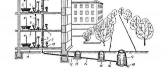
- distribution - channels are attached directly to racks, buildings, distribution cabinets, as well as to cable poles. In order for the installation to be competent and there is the possibility of further repairs on the site, special wells are made;
Distribution cable duct
- main - is that a stationary well is installed, and from it there is a branching in different directions. Moreover, each of them must be attached to the distribution cabinet. This type usually includes pulling additional and main cables.
Main cable drainage
Cable duct functions
- Protection of wires from atmospheric agents, soil and road loads, etc.
- Possibility of replacing, repairing, branching electrical or telephone networks without opening the soil or destroying the road surface.
Types of cable sewer systems
The most common classification of cable sewers is based on the method of laying sewer pipelines.
- Installation of pipes can be carried out in pre-prepared trenches. In this case, the soil is removed.
- Trenchless installation allows, when running the cable underground, not to violate the integrity of the soil surface. This installation is carried out using horizontal drilling.
Cable sewers also differ in the shape and cross-sectional size of the wells and pipes themselves, as well as the material from which the sewer elements are made.
You may be interested in information - inspection well
Wells can be reinforced concrete, brick or plastic. Pipes made of plastic, asbestos, concrete, fiberglass, pitch fiber and steel are used for cable ducting. The most common are asbestos or plastic. Sometimes, instead of pipes, special plastic blocks with several sections are used - multichannels.
Multichannels connected to each other
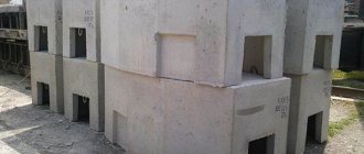
Which well is better
While reinforced concrete wells with asbestos-cement pipes can work reliably and for a long time in harsh conditions, plastic wells do not always withstand them. The main reasons are unreliable pipe connections.
The SKTB-TOMASS company tried to introduce innovative ideas for the introduction of plastic wells in 2005. She developed the design of the PKK-2U-M1 brand made of polyethylene, documentation and mastered its own production. The device contains an internal steel frame and must be closed from above with a concrete slab with a hatch resting on the ground. Only in this case can the structure be a substitute for concrete.
Modern manufacturers of plastic wells know practically nothing about this design and more than ten years of experience in its operation. In all the lines of manufactured models it is impossible to find a single design that continues the work of the PKK well. Outwardly they seem convenient, but in fact they sell barrels, septic tanks and tanks, etc. containers made of plastic. The instructions say nothing about their flammability, the effect of hot asphalt, or the possibility of repair when the neck is demolished by a bulldozer. We are not impressed by the modest size of plastic containers, which cannot compete with concrete products for multi-pair sewers. The lightness of the structure has become a disadvantage since it requires support and anchor plates and specially fitted molds. All this increases the cost of the well.
Plastic consoles and brackets glued to the walls are not nearly as reliable as elements of reinforced concrete wells made of metal. It is impossible to install couplings in many plastic wells, and if they do manage to be “stuffed”, the bending radii of the cables become completely unacceptable.
When installing a lightweight polymer container, for greater reliability, you have to mount a sarcophagus made of a concrete slab with a cast-iron hatch on top, and install another one below as an anchor.
Communication cable wells
These structures are installed at intervals of 25 to 150 meters from one another. There are KKS (communication cable wells) made of bricks or reinforced concrete. Their size depends on the number of channels carried through them. Typically, standard prefabricated or reinforced concrete solid structures are installed. KKS come in standard or standard design. According to their design features they are divided into:
- walk-through (also called straight) - they are installed in areas where the installation of cable ducts is implemented without turns or when the angle of deviation of the route from the center is no more than 30 degrees;
- corner;
- branching - they are placed in the places of inlet or outlet of channels;
- station - they are located near buildings where cable equipment is located.
KKS are distinguished regarding the load on them:
- for roadways - 80 tons;
- for pedestrian areas - 10 tons.
Wells can also be rectangular, have many sides, etc. According to the sizes they are made small, medium and large.
Calculation of the force required to lay a power cable in a trench
The question of calculating traction force is asked by designers and specialists of installation teams when choosing equipment such as a cable winch, a cable for it, a cable stocking, an ultrasonic clamp, etc.
The applied force required to move the cable depends on the following parameters:
- Linear weight of cable M (kg/m);
This parameter is indicated in the cable passport, or in the cable characteristics on the website of its manufacturer. Due to the fact that the cable is usually laid in sections of several hundred meters, it will be more convenient to use the weight of one meter of cable.
- Installation section length L;
Parameters 1 and 2 allow you to determine the total mass of the cable being moved.
- Friction coefficient Kt;
During the installation process, the power cable comes into contact with various objects. These can be cable rollers or soil surfaces along which it moves if the latter are not in use (earth, ice, etc.). Each of these elements has its own coefficient, presented in Table 1, which must be taken into account in the calculation.
Table 1 - Friction coefficients of various materials
| Material | Friction coefficient (Kt) |
| Polyethylene | 0,29 |
| Asbestos cement (for example, city cable drainage pipe) | 0,32 |
| Concrete | 0,38 |
| Polyvinyl chloride | 0,3 |
| Polymer with a layer of solid lubricant | 0,1 |
| Earth (in a trench) | 0,8 |
| When laying on rollers, when sliding on the ground is excluded, since the number of rollers is set in sufficient quantity | 0,25 |
| When laying on rollers, when sliding on the ground between the rollers is possible | 0,35 |
| On the ice | 0,03—0,04 |
To reduce the coefficient of friction, special lubricants can be used.
In the simplest case, when the power cable is laid along a straight path in a horizontal plane in a trench or collector, the traction force can be calculated using the formula:
Fg (kN) = m (kg) * L (m) * Kt
Where:
- Fg (kN) - traction force required to pull a straight section of cable in a horizontal plane
- m (kg) - weight of 1 meter of cable
- L (m) - length of the installation section (construction length)
- Kt is the friction coefficient, selected depending on the material, the values are given in Table 1.
Example. If the power cable is pulled in a trench, it is worth considering the coefficient of 0.8; 0.25 or 0.35 depending on the number of linear cable rollers used. If the power cable is pulled in a collector without rollers, then a coefficient of 0.38 must be taken into account - for concrete.
- Route inclination angle
If the power cable is not laid in a horizontal plane, but has some rise or fall, then a component is added to the formula depending on the angle of inclination Kn.
Fsp (kN) = m (kg) * L (m) * (Kt*cos a + sin a)
Where
- Fsp (kN) - traction force required to pull a cable in a straight section with ascent or descent
- m (kg) - weight of 1 meter of cable
- L (m) - length of the installation section (construction length)
- Kt is the friction coefficient, selected depending on the material, the values are given in Table 1.
- a is the angle of inclination. The values of the sines and cosines of the slope angles are given in Table 2
Table 2. Cosines and sines of the slope angles of the route
| Route inclination angle (a, degrees) | cos a | sin a |
| 30 degrees | 0,866 | 0,5 |
| 45 degrees | 0,7071 | 0,7071 |
| 60 degrees | 0,5 | 0,866 |
| 90 degrees | 0 | 1 |
| 120 degrees | -0,5 | 0,866 |
| 0 degrees | 1 | 0 |
| 135 degrees | -0,7071 | 0,7071 |
| 150 degrees | -0,866 | 0,5 |
- Cable route turns
If the installation site has a turn, then another coefficient is added to the formula, taking into account the additional force that is necessary to overcome it.
Coefficient to take into account the force required to overcome the turn of the cable route:
Kug = e (Kt*a)
Where:
- Kug - coefficient showing the effort to overcome the bend of the channel when pulling the cable
- e is the base of the natural logarithm
- Kt - friction coefficient
- a - bending angle (if a = 0, then Kug = 1)
- The force of unwinding the power cable from the cable drum. This parameter is difficult to calculate, but can be easily minimized by using specialized devices - cable jacks. These devices will be described in more detail below.
Based on what was described above, the general formula for calculating the total traction force of laying a power cable in a section with ascent/descent and turns will be equal to:
Kp = (Fg + Fsp)*Kug * N
Where:
- Kp - total traction force of laying the power cable
- Fg (kN) - traction force required to pull a straight section of power cable in a horizontal plane
- Fsp (kN) - traction force required to pull a power cable in a straight section with ascent or descent
- Kug - coefficient showing the effort to overcome the bend of the channel when pulling the power cable
- N – number of turns of the cable route
Cable inspection wells
The design solution of the KKS assumes the presence of two compartments - lower and upper. Straight wells have through holes at the ends for placing packages. Before installing the well in the desired location, a pit is prepared. When the device is mounted, proceed to placing the hatch. Typically, the kit includes two covers: the top one is made of cast iron, and the bottom one is made of steel with shut-off fittings for a padlock. From the inside, on the walls of the KKS there are consoles, thanks to which the cable is laid in the sewer. When arranging cable ducts in an open version, passages through the tracks are made by puncture or using horizontal drilling. In the second case, a drill is used to make a hole for the sewer network, which, during the return process, pulls the pipe into the finished space. In some cases, in large populated areas, tunnels and sewers are built underground specifically for laying utilities. The personnel serving them have convenient access. These facilities are equipped with ventilation systems and stationary lighting fixtures.
Reinforced concrete wells
The products consist of two parts - upper and lower. There is a window at the top for installing a hatch. The shape of the wells is made round, square or in the form of a prism.
Concrete is prepared with fine aggregates to ensure water resistance and water resistance. The product may contain a hydrophobic coating to protect against groundwater. The structure is reinforced with a frame made of steel mesh or reinforcement, which is assembled by spot welding.
The container is equipped with pipes for cable entry. They are connected to cable sleeves using compression couplings, rubber cuffs or extrusion welding.
What do you need to know about telephone sewer design?
Designing a telephone sewer system is, perhaps, the first stage of the construction of a KKS.
The document must contain the following information:
Cable duct project
- the location of the route for laying the pipeline on the site;
- minimum number of obstacles;
- estimated costs for protecting pipes from electricity;
- the number of mechanisms that are planned to be used during installation.
The design documentation also specifies the minimum distance from railways.
Design of cable ducts near roads
SNiP provides certain requirements for the installation of telephone sewerage.
Here are some of them:
- the surface of the cable must be smooth, and the pipeline itself must be durable, frost-resistant and resistant to groundwater;
Groundwater resistant cable with smooth surface
- for small-channel blocks, polyethylene pipes with a diameter of 55-58 mm are used. For other types of cable, reinforced concrete and asbestos-cement pipes with an internal cross-section of 90-100 mm are used. The pipeline must not have a harmful effect on the cable sheath;
PVC pipes 55 and 100 mm in diameter
- more than 6 optical cables of the same type are not allowed in one communication channel;
- installation of wire cores in a lead sheath should not be carried out at air temperatures below -20 degrees Celsius, and the use of material in a polyethylene sheath is allowed up to -10 degrees;
Cable duct diagram
- The input of city telephone and coaxial trunk cables is organized in the lower rows of the cable duct . In collectors, wires can be arranged in two rows, but their specific sequence must be observed. On the one hand - wire broadcasting, communications, heat pipes, and on the other - power, wire broadcasting, communications and water pipes.
Laying cable ducts
Cable laying in cable ducts can be carried out in different ways, which depend on its weight.
For example, if it is less than 1500 kg/km, then the installation can be done manually; with a weight of up to 6 thousand kg/km, a cable machine/hand winch is required; if a cable of more than 6000 kg/km is used, there is no need for a winch.
Layout of cables
7.1 Optical cables are laid out in the shape of transit wells, starting from the middle of the span in both directions, using the reserve stretched out in the last well (20–25 m), laid them on the console of the corresponding row in the streams closest to the bracket (preferably in the first console place) and secured dressing. The laid out cable should not intersect with other cables running in the same row or obscure the channel openings.
7.2 Since optical cables are not very rigid and can sag when laid on consoles, it is advisable to place them in halves of polyethylene pipes or polyvinyl chloride tubes pre-laid on consoles.
7.3 The cable reserve left in the well for mounting the coupling is rolled up into rings with a diameter of at least 1 m, laid against the wall and attached to the brackets. The cable reserve required for installation of the coupling must be 8 m from the channel at both ends of the cable.
7.4 After laying out the cable, remove all guide funnels and other devices. Then control measurements are made of the attenuation of the optical fiber, which must be within the established kilometer norm. After checking the laid length of the cable, the polyethylene caps at its ends must be restored.
Features of installation of a cable sewer system
- The depth of the cable channels depends on the material of the pipes and the installation location and can range from 40 to 200 cm. Concrete pipes are installed the deepest, while plastic pipes are laid at the smallest depth. In addition, pipelines passing under tram tracks are buried as deep as possible, under pedestrian areas at a minimum, and under highways at an average depth.
- When laying pipes, it is necessary to maintain a slope of 4 mm per meter. This allows water trapped in the channels to drain out.
- Pipes and cables in them between wells must be laid in a straight line. Only a small displacement is allowed, which should be no more than 10 mm per meter of pipe.
- Depending on the resulting cable laying pattern, inspection wells are installed every 25-150 meters.
Cable in tunnel
- Inside the basements of buildings, large sewers, etc. It is not advisable to lay cables in pipes; here the wires are pulled through special consoles.
- If several pipes are laid in a trench, then those of them in which the wires with the lowest voltage will be stretched should be closest to the surface of the earth.
- The optimal diameter of cable drainage pipes is considered to be 100 mm. In previously used pipes with a cross-section of 15 cm, cable pulling was more difficult.
- Electrical and telephone wires cannot be laid in the same pipe.
- It is necessary to choose the right manhole in terms of volume and depending on the location and function performed.
Don't miss: Patchwork style tiles for the kitchen: photo of a kitchen with patchwork tiles
Cable cutting
8.1 Cable cutting must be carried out by trained and certified personnel. It is necessary to use only a special set of tools for installing optical cables.
8.2 The length of the groove is indicated in the special instructions for installing couplings. To carry out incoming inspection, the length of the cutting section is no more than 300 mm.
8.3 The cutting of DPL brand cable must be carried out in the manner described below.
8.3.1 Using a roller knife (or stripper), perform a transverse opening of the outer sheath of the cable along with the tape armor.
8.3.2 From the point of transverse opening to the end of the cable, using a plow knife, make a longitudinal cut of the sheath and armor (preferably two oppositely located).
8.3.3 Using pliers, remove the outer sheath of the cable along with the armor.
8.3.4 To carry out grounding, make a transverse and longitudinal cut of the shell at the required length, spray it with a flame or a stream of hot air so that the shell comes unstuck from the armor, and remove the shell from the armor with pliers.
8.3.5 Using a roller knife, perform a transverse opening of the inner cable sheath.
8.3.6 From the point of transverse opening to the end of the cable, use a plow knife to make a longitudinal cut of the inner sheath (preferably two oppositely located).
8.3.7 Use pliers to remove the inner sheath of the cable.
8.3.8 Remove the winding thread from the section of the cable free of sheaths.
8.3.9 Using gasoline or special liquid D-Gel, remove the intermodular hydrophobic filler.
8.3.10 Unwind the optical modules.
8.3.11 Remove the central power element, leaving the length necessary for installing the cable into the coupling.
8.3.12 Opening optical modules in order to remove optical fibers should only be done using a precision tool that prevents damage to the optical fibers, for example, a special stripper. Make a cut on each optical module.
8.3.13 Carefully pull off the module shell.
8.3.14 Remove the hydrophobic filler with a special liquid D-Gel.
8.3.15 Wipe the fibers with isopropyl alcohol.
Design rules: norms and requirements, SP
When designing and constructing cable ducts, certain norms and rules must be observed.
Construction standards provide for the following protection methods:
- from electrochemical corrosion,
- from water and gas getting into pipelines and wells,
- from mechanical influences of the soil and ground shifts.
If possible, an impassable part of the road is selected for laying cables to avoid intersections with rail tracks and streets.
A set of design and construction rules has been developed for telecommunication systems of buildings and structures. It regulates all the necessary requirements for laying cables. The Ministry of Communications issued document VSN 116-93 to regulate departmental building standards.
Requirements for installing inspection wells:
- The distance between wells should not be more than 150 m.
- Reinforced concrete wells, prefabricated and fully prefabricated structures are used. Wells made of other materials are used if their use is justified. Recently, ready-made plastic wells with stiffening ribs are often used, especially with a light load.
- To increase the volume, it is allowed to build new wells next to existing ones.
Requirements for laying pipelines:
- The inner surface of the pipeline must be smooth.
- The pipeline must be resistant to frost, physical stress, and waterproof.
- For distribution and main networks, polyethylene pipes with an internal diameter of 55-58 mm are used. In other cases - concrete and asbestos-cement pipes 90-100 mm, or from recycled polyethylene with an outer diameter of 63 and 110 mm.
General norms for laying cables in pipelines:
- Cables of various types can be laid in cable ducts. But no more than 5-6 cables of the same type in one pipe, and they should not occupy more than 0.75 of the channel diameter.
- Armored cables can be laid without polyethylene pipes. Unarmored ones are laid in small cross-section collectors.
- Cables of wired broadcasting networks can be laid together with communication cables if their combined voltage does not exceed 240 V, and the length of the section is controlled.
Temperature requirements:
- Work related to laying cables in a lead sheath in the open air is carried out at a temperature not lower than -20°C.
- The cable is laid in a polyethylene sheath at a temperature of -10°C.
Requirements for placement and method of laying cables:
- If the cables are located in two rows from the passage, then their sequence from top to bottom is as follows: 1 row - wire broadcast cables, communication cables, heat pipes; Row 2 - power cables, wire broadcast cables, communication cables, water pipes.
- When arranged in one row, the sequence from top to bottom is as follows: power cables, wire broadcast cables, communication cables, heat pipes, water pipes.
- Depending on the weight of the cable, a different pulling element is used: steel rope, steel wire, synthetic rope.
Application of cable with copper conductors
The use of a cable with copper conductors requires installation of a galvanic steel stocking on the sealed end of the cable.
It is made to fix the wire workpiece. The copper cable is laid using a certain technology and attached to a drum like a jack.
The cable is fed into the upper part of the drum, and there are polyethylene bushings at the entrance to the channel. The cable tension is constantly monitored.
When installation is completed, the ends are checked for leaks.
Differences between double-wall pipes and conventional pipes
On difficult sections of the route, double-walled pipes are used. They have many advantages over conventional ones.
- High ring rigidity allows it to withstand significant loads (especially for corrugated pipes).
- Despite their rigidity, double-wall pipes are flexible enough to bend around obstacles.
- Withstands temperature changes while maintaining elasticity.
- They have a nylon broach, the length of pipes in coils is from 35 to 150 m.
- The minimum bending radius is 8 diameters.
Basic requirements for transportation and storage
4.1 During transportation, drums should not lie on the cheek and should be securely fastened. When fastening drums, it is prohibited to pierce the cheek boards and drum casing with nails and staples.
4.2 The optical cable must be transported only on the manufacturer's drum.
4.3 When loading (unloading) drums, it is necessary to use special equipment to prevent impacts and mechanical damage to the drums. It is prohibited to throw drums off the vehicle or roll them down hills.
4.4 After transportation, drums must be checked for damage and integrity of protective devices.
4.5 During storage, drums must be protected from mechanical influences, as well as from sunlight, precipitation and dust. The drums should not rest on the cheek. It is not allowed to install drums on top of each other (Fig. 1). Storage temperature: from minus 60 ºС to 70 ºС. The ends of the optical cable during storage must be protected using special sealing heat-shrinkable caps.
4.6 The drum casing is removed only after the start of work, after installing the drum on the device for winding the cable from the drum, with the permission of the responsible work manager.
Rice. 1. Storing optical cable reels
Construction of trenches
To carry out excavation work, special equipment is usually used, and in places where communications pass close, pits or trenches are dug manually, and only in the presence of employees of the organizations whose utility networks are marked on the drawings. If the soil crumbles into trenches, their walls are strengthened with spacers or special shields. The bottom of the ditches is arranged so that the pipes laid in a package are located with an inclination in the direction of the wells, which should be approximately 3-4 millimeters per meter.
Trench characteristics and maximum number of power cables in a trench
This section provides basic reference data, which are described in more detail in PUE 7.
Figure 1. Trench characteristics
The distance between power cables with a voltage of 10 kV in the ground in a trench must be at least 100 mm, between cables with a voltage of 20 - 35 kV - 250 mm (requirements clause 2.3.86. PUE). The distance between control cables in a trench is not standardized. Depending on the width of the trench and the type of cables being laid, their number in the trench (ground) will differ slightly. However, it cannot exceed 6 cables. If it is necessary to lay more than 6 cables, it is recommended to use two or more trenches.
If it is necessary to stretch more than 20 power cables in one direction, it is recommended to place them in tunnels or on overpasses (requirements clause 2.3.25. PUE).
Table 3. Depth of power cable in the ground and trench parameters: standards
| Trench type | Trench width, mm | Trench depth | Depth of power cables |
| T-1 | 200 | 900 | 700 |
| T-2 | 300 | ||
| T-3 | 400 | ||
| T-4 | 500 | ||
| T-5 | 600 | ||
| T-6 | 700 | ||
| T-7 | 800 | ||
| T-8 | 900 | ||
| T-9 | 1000 | ||
| T-10 | 300 | 1250 | 900 |
| T-11 | 500 | ||
| T-12 | 600 | ||
| T-13 | 800 | ||
| T-14 | 900 | ||
| T-15 | 1000 |
Table 4. Maximum number of power cables in a trench: standards
| Trench type | Cable Type | Number of cables in the trench, pcs. Diameter, mm | |||||||
| To 10 | Up to 20 | Up to 30 | Up to 40 | Up to 50 | Up to 60 | Up to 70 | Up to 80 | ||
| T-1 | Tests | 1 – 10 | 1 — 5 | 1 — 3 | 1 — 2 | 2 | |||
| T-2 | 11 — 20 | 6 — 10 | 4 — 6 | 3 — 5 | 3, 4 | ||||
| T-3 | 21 — 30 | 11 — 15 | 7 — 10 | 6, 7 | 5, 6 | ||||
| T-4 | 31 — 40 | 16 — 20 | 1 — 13 | 8 — 10 | 7, 8 | ||||
| T-5 | 41 — 50 | 21 — 25 | 14 — 16 | 11 — 12 | 9, 10 | ||||
| T-6 | 51 — 60 | 26 — 30 | 17 – 20 | 13 — 15 | 11, 12 | ||||
| T-7 | 61 — 70 | 31 — 35 | 21 — 23 | 16 — 17 | 13, 14 | ||||
| T-8 | 71 — 80 | 36 — 40 | 24 — 26 | 18 — 20 | 15, 16 | ||||
| T-9 | 81 — 90 | 41 — 45 | 27 — 30 | 21, 22 | 17, 18 | ||||
| T-1 | Power, voltage up to 20 kV | 1, 2 | 1 | 1 | 1 | 1 | 1 | 1 | 1 |
| T-2 | 2 | 2 | 2 | 2 | 2 | ||||
| T-3 | 3 | 3 | 3 | 3 | 2 | 2 | |||
| T-4 | 4 | 4 | 4 | 3 | 3 | 3 | |||
| T-5 | 5 | 5 | 4 | 4 | 3 | ||||
| T-6 | 6 | 6 | 5 | 5 | 4 | ||||
| T-7 | 6 | 5 | 5 | 4 | 4 | ||||
| T-8 | 6 | 6 | 5 | 5 | |||||
| T-9 | 6 | 6 | |||||||
| T-1 | Power, voltage 20 kV | 1 | 1 | 1 | 1 | 1 | 1 | 1 | 1 |
| T-3 | 2 | ||||||||
| T-4 | 2 | 2 | 2 | 2 | 2 | ||||
| T-5 | 2 | 2 | |||||||
| T-6 | 3 | ||||||||
| T-7 | 3 | 3 | 3 | 3 | |||||
| T-8 | 3 | 3 | 3 | ||||||
| T-9 | 4 | 4 | |||||||
| T-10 | Power, voltage 35 kV | 1 | 1 | 1 | 1 | 1 | 1 | 1 | |
| T-11 | 2 | 2 | 2 | 2 | 2 | ||||
| T-12 | 2 | 2 | |||||||
| T-13 | 3 | 3 | 3 | 3 | |||||
| T-14 | 3 | 3 | 3 | ||||||
| T-15 | 4 | ||||||||
Laying the pipe package
When there is a natural difference in height in the area, then the pipe package is placed at the same depth along the entire length between the inspection structures, but at a distance of ten meters from the inspection devices, the laying is done with a slope. This is necessary to insert the pipes into the well at the required height. Align the package relative to the horizon using a cord that is pulled along the side border of the ditch.
When laying the package, the pipes are placed along the trench, maintaining a distance of 20-25 millimeters between them. This free space is covered with earth and compacted. The rows of channels in the package must be separated by layers of poured and then compacted soil at least 25 millimeters thick.
The ends of asbestos-cement pipes between the devices are combined using heated polyethylene couplings or cuffs fixed with cement mortar. There is another way of joining, when a metal cuff and resin tapes are used.
If a flexible double-wall pipe for cable ducting is used, it is connected into a package by welding the joints.
Laying copper cable
Cables with a small capacity (such as distribution or intrazone copper cables) with a quantity of no more than 100 pairs are usually tightened manually. In this case, a so-called “stocking” made of galvanic steel is placed on the sealed end of the cable. The workpiece wire is attached to the sleeve or loop at the end. Cable laying is carried out in the following sequence:
- The drum with the cable to be laid must be secured on the side of the receiving device to devices (this can be trestles, carts, etc.). It is fed from the top of the drum.
- At the entrance to the hole, split polyethylene bushings or cable elbows are placed to protect the cable covering from scuffing.
- Having received the appropriate signal from the work performer, the workpiece with the cable connected to it is pulled out in the receiving structure, and at the feeding device they begin to adjust the tension of the cable coming from the drum. After completing installation in the span, the ends of the cable are checked for leaks and laid on the console. Its ends are marked with tags marked A or B.
- It is permissible to lay the cable in the sewer in winter in a polyethylene hose at a temperature of at least 10 degrees below zero, and in a lead sheath - at least minus 20.
Don't miss: How to lay ceramic tiles: advice from professionals on laying chord cerama marazzi
Laying fiber optic cable
The optical cable is laid in the sewer in the same way as is done with a copper cable. True, there are a number of technological nuances associated with the design of the optical fiber; as a result, it can be stretched over a kilometer-long segment, and in sections with turns, up to half a kilometer long. Since optical fiber is poorly affected by external mechanical loads, it is customary to protect it in sewers with polyethylene tubes with a diameter of 25-63 millimeters. They are pulled into the channel and the cable is placed directly into them. In this case, laying a fiber-optic cable in a sewer is always done using a swivel and with a device for gripping the fiber-optic cable, compensating for its stretching.
Before laying
5.1 Preparation of cable ducts for laying optical cable includes: installation of fences, preparation of wells, preparation of cable ducts, preparation and cleaning of cable ducts and, if necessary, laying of an auxiliary pipeline (polyethylene pipes).
5.2 Work in cable ducts for laying cables must be carried out in strict compliance with the requirements of the current “Occupational Safety and Health Rules when working on cable communication lines and wire broadcasting”, the main of which are: fencing open wells and work areas, checking wells for the presence of hazardous gases, ventilation of wells, taking precautions in the presence of cables with remote power supply voltage and wire broadcasting cables in wells. Personnel who have completed a training course in technological rules and work methods are allowed to carry out work.
5.3 In accordance with safety requirements, fences - barriers - are installed near the wells being opened on both sides. On the roadway, fences should be installed on the side of traffic at a distance of at least 2 m from the well hatch. In addition, warning signs must be installed at a distance of 10–15 m from the fence facing traffic. In case of poor visibility, additional light signals must be installed. Before starting work in wells located on the roadway, it is necessary to notify the local traffic police authorities about the place and time of the work.
5.4 To prevent accidents and damage, wells must be opened using appropriate devices, for example, lid lifters, lifting pliers. Under no circumstances should picks, shovels, hammers, crowbars, files or other metal tools be used. Firmly frozen lids can only be dislodged using wooden tampers without metal edging or a hot defrost device. The use of metal tools to remove snow and ice from manholes on wells is permitted only if this does not create a spark. Due to the risk of gas explosion, defrosting using an open flame is prohibited.
5.5 Before workers lower into the well, it is properly ventilated. To determine the presence of gas in the sewer, it is necessary to use a gas analyzer. No work should begin until the sewer is free of gas. If gas is detected, the work manager must be notified immediately. In the wells in which you are going to work, it is necessary to check the absence of gases: methane, propane and carbon dioxide. At least one channel (preferably the upper one) is temporarily opened, and after 10–15 minutes, a check is made again for the absence of harmful gases. If the well is being descended for the first time, a worker must remain outside, even if no gas was detected. A worker descending into a well should be secured with a rescue rope. When descending, do not step on cables, couplings or cable fastenings.
5.6 Channel selection
5.6.1 Laying optical cables in cable ducts should be carried out, as a rule, in free channels and located, if possible, in the middle of the block vertically and at the edge horizontally. No more than six optical cables can be laid in a free channel. It is not allowed to use a channel occupied by unarmored optical cables laid without protective polymer pipes for laying armored optical cables. The laying of unarmored optical cables in a cable duct occupied by cables with metal conductors and optical armored cables must be provided in pre-laid protective polyethylene tubes. Optical cables with armor made of fiberglass rods, steel wires and tapes with a protective polyethylene sheath on top of the armor can be laid both through free and occupied channels without being pulled into a polyethylene pipe.
5.6.2 It is allowed to lay several cables or protective polyethylene tubes in one channel, provided that the total cross-sectional area of the cables and (or) pipes does not exceed 0.6 of the channel area.
5.6.3 When laying optical cables in cable structures together with power cables, optical cables and power cables must be laid in separate channels; in the case when the cable structure does not have a dedicated channel for laying optical cables, the placement should be made only under or only above the power cables; however, they should be separated by a partition.
Dividing partitions must have a fire resistance rating of at least 0.25 hours.
5.7 Cleaning the channel.
5.7.1 If, as a result of penetration of groundwater into the canal, the canals in some places are filled with sand, clay, silt, etc., the canals must be cleaned. For cleaning, special steel scoops should be used.
5.7.2 It is recommended to remove ice formed in the channel using steam from a mobile steam generator. If cleaning the channels does not give positive results, then this section of the sewer should be opened and repaired. If necessary, inserts are made from sections of new solid or split pipes.
5.7.3 In the process of preparing the cable duct for cable laying, the permeability of the channels is checked. To do this, the test cylinder is connected with a carabiner to a special brush. The diameter of the test cylinder should be: 92 mm - for asbestos-cement and concrete pipes with a diameter of 100 mm, 82 mm - for asbestos-cement and concrete pipes with a diameter of 90 mm, as well as polyethylene pipes with a diameter of 100 mm.
5.7.4 If the test cylinder and brush pass through the channel with great difficulty, then they should be removed from the channel. It is advisable to replace the blank wire with a rope. The rope is attached on one side to a test cylinder, on the other side to a special brush. By dragging the cylinder and brush several times back and forth through a difficult place, the channel is cleared of contaminants.
Instead of a metal brush, a sand trap, a scraper on a steel tube, or a brush can be used.
Channels made of plastic pipes must not be cleaned with sharp-edged tools (such as steel wire brushes).
Cleaning tools and cable pulls are usually pulled through the duct manually by several people. If the cleaning device gets stuck, it is pulled back with a winch. If contamination is very high, multiple passes may be required and possibly flushing of the cable duct.
It is recommended to carry out comprehensive cleaning using a steel scoop. After cleaning the channel, the cylinder and brush are removed from the initial well. A blank wire is attached to the brush and again pulled through the channel along with the wire.
5.7.5 Cleaning of occupied cable channels should be carried out in ways that prevent damage to previously laid cables.
5.7.6 If subsidence of asbestos-cement pipes is detected at the joints (displacement of centers), then under no circumstances should a cable be laid in them. It is necessary to take measures to eliminate pipe subsidence and only then begin laying the cable.
5.8 Preparation of the channel when laying without protective pipes.
5.8.1 To lay a cable in a cable duct channel, you must first lay a steel wire with a diameter of 3 mm in it - make a channel blank. The channel is prepared in three ways: with metal sticks 1 m long, screwed together into a whip; polyethylene tube, up to 150 m long; glass rod, enclosed in a polyethylene shell, with an outer diameter of 11 mm and a length of up to 150 m, wound on a special vestibule, which ensures ease of working with the rods, preventing its spontaneous unwinding.
5.8.2 Preparing channels with metal sticks is done by pushing them into the channel, increasing them by screwing. When the first stick comes out of the adjacent well, a blank steel wire with a diameter of 3 mm is attached to its tail tip and the sticks are pulled out, unscrewing one at a time. On straight sections of the route or when preparing free channels, it is recommended to pass the sticks without unscrewing them through several wells while this movement is possible.
Sticks are recommended for use when preparing difficult-to-pass channels. When working with sticks, you should avoid spinning them in the channel. If unwinding has occurred, then to remove the string of sticks, you should use a special funnel to catch and screw the loose string into the channel.
5.8.3 Preparation of channels with a polyethylene tube is carried out by pushing, if possible, through all transit wells. In difficult sections of the route, workers provide auxiliary tightening of the tube. The blank wire should be attached to the tail tip and pulled along with the tube. If advancing the tube becomes impossible due to obstacles in the canal, it is recommended to turn the tube clockwise and counterclockwise several times while simultaneously pushing it into the canal.
5.8.4 The most effective way is to prepare channels using ultrasonic testing devices. In this case, the glass rod is pushed into the channel, unwinding it from the vestibule through the transit wells together with the blank wire attached to the tail tip (with the rod being tightened in the transit wells). If the mass of the optical cable is less than 0.3 kg/m, it is allowed to pull it into the channel with a glass rod.
5.9 Preparation of the channel when laying in protective pipes.
5.9.1 The protective polyethylene tube is laid from a coil installed at the well on a mobile vestibule, or from a coil manually. The end of the tube, equipped with a tip, is inserted into the channel and pushed forward along it along the entire length of the span(s). If there are transit wells, the tube is tightened.
If advancement of the tube becomes impossible due to obstacles in the channel, the tube must be rotated several times around its axis while simultaneously pushing.
5.9.2 In each well, the polyethylene tube is cut with a hacksaw, leaving a margin of 25 cm from the end of the channel. They do it as follows. At the entrance of the last well, an anti-theft device is installed on the tube, which is a stop that prevents the tube from moving when it is wired and laid (taking into account its direction).
Next, the pipe is fed back through the channel, cut off at the inlet of the next well and pushed back through the channel. Next, the tube is cut off at the outlet of the previous well and again pushed through the channel. This is done in every transit well.
5.9.3 If it is possible to lay the cable through transit wells without tightening, it is allowed not to cut the tube in these wells. In this case, it is necessary to provide a supply of pipe for laying it on the console.
5.9.4 Simultaneously with cutting the tube, one anti-theft device is installed at the channel inlet and outlet for the period of cable laying. In cases where the preparation of a laid polyethylene tube and laying of a cable are not carried out immediately, but after some time, during which the wells can be filled with water, to prevent sand, clay, and silt from entering the laid tubes, they are temporarily protected in each well with polyethylene caps with a winding around them joint with 5-7 layers of adhesive plastic tape.
5.9.5 The polyethylene tube is prepared using galvanized steel wire with a diameter of 3 mm or steel cable. If the inner surface of the tube is coated with a solid lubricant, then such a pipe must be prepared using means that will prevent damage to the solid lubricant. This is done in two ways - with a steleplastic rod or with a pneumatic drill. When laying a cable weighing up to 0.3 kg/m, it is allowed to prepare the tube with fiberglass rod.
5.9.6 Preparing a protective pipe with a pneumatic boring machine is recommended for spans from 80 to 150 m. This method can be used for preparing only clean, free channels and auxiliary pipelines from polyethylene tubes. Harvesting work using a pneumatic device is carried out by two workers. A rope winch and a charged cylinder of compressed air are installed at the head well (a compressor can be used). A torsion compensator is connected to the rope, and then the piston of the pneumatic harvesting device is attached. The piston is inserted into the prepared channel. An end plug is installed at the channel entrance, through which a rope is passed and a pneumatic line is connected. The assembled device is inserted all the way and the rubber seal is manually compressed to the maximum. Open the cylinder valve and set the operating pressure to 0.4–0.8 MPa using the pressure gauge. Then the lever of the pneumatic valve is sharply pressed, while air is supplied into the channel through a flexible hose. Under the influence of compressed air, the piston moves, pulling the rope into the channel. The end of the shot is determined by the weakening of the rope. After this, the pneumatic valve lever is released and the valve is closed. Then, using a rope, a wire or cable is pulled into the pipe.
Cable tightening technique
The technology for laying cables in cable ducts depends on its type. If a tunnel type of network is used, the wires are laid on brackets attached to the walls. The simplest method consists of two steps:
- a steel rope is pushed into the pipe;
- hook the cable and pull the rope, thereby pulling the cable into the pipe.
In this way, not only installation is carried out, but also cable replacement in the cable duct.
The first action is input control. This is receiving the cable, checking its parameters, measuring the length. The second step is to group the cables according to their parameters. This is necessary to combine them into a bun for styling together. Using a separate pipe for one cable is not economically viable, so they are connected in threes (this is the maximum).
Tightening is carried out using ultrasonic testing (installation of a channel blank). The connection to the rope is made so that the load falls only on the sheath and the power central element (steel conductor intended for reinforcing the wire). When tightening, torsion compensators are used to keep the cable in working condition.
Cable duct installation
Cable drainage has nothing to do with drainage systems. This is a utility network that provides placement and protection of cables and wires for power supply, communication, and information transfer.
It is customary to use two methods of underground lines:
- laying in a pipe;
- use of cable duct.
The pipe gasket is used for one, separate wire. Typically, this method is used when it is necessary to lay an additional or temporary line. Sometimes several wires are placed in a pipe at once if they perform the same tasks and do not interfere with each other.
Cable drainage is an underground communications system for housing multiple connecting lines. Laying cables in cable ducts is a complex and expensive undertaking, so it is not practical to build a system for individual wires. Most often, telephone wiring is done in this way. There are a lot of them, so the construction of trenches and canals is economically justified.
Cable duct design may vary. It depends on the type and purpose of the wires. For example, laying a telephone cable in a sewer requires tightening a bundle of pairs into relatively small pipes. If it is necessary to lay a power line, tunnels with wall-mounted cable mounts are used. The method of installation or maintenance depends on the type of installation.
Based on the construction method, there are two types:
- trenchless. Special horizontal drilling techniques are used. This method allows you to preserve the landscaped surface of the earth;
- trench. They build in the usual way, using earth-moving equipment. At the same time, the earth's surface suffers serious interference, and the improvement of the line is disrupted.
The cable duct includes;
- trenches or sections of underground pipelines;
- inspection wells.
The former are used for placing wires, the latter are necessary for connecting, repairing or replacing failed sections of the line.
The main feature of cable ducting is the absence of liquids involved in the operation of the system. this allows you to significantly reduce the depth of the trenches, which reduces costs and increases the speed of installation work.
The procedure for installing cable ducts: step-by-step instructions
Cable laying work includes the following:
- The necessary calculations are made and a design drawing is drawn up. It is imperative to take into account the presence of other communications and coordinate the digging of trenches with their owners.
- After carefully marking the area, you can begin digging a pit. In this case, the width of the pit should be 40 cm greater than the width of the well. A 15 cm thick sand cushion is poured onto the bottom. If the soil in this area is characterized by a high groundwater level, the bottom is concreted.
- Special equipment is used to dig trenches, but in the case of nearby external communications, the digging is done manually. The width and length of the trenches depends on the number and material of pipes. If the soil crumbles, the walls are reinforced with sheets of wood. Pipes are laid taking into account the slope from the center of the pipe to the wells.
- Wells are installed. They must stand level on a concrete base. Wells must be freely connected to cable pipes. If there is a loading chamber, it is filled with cement.
- Pipes are laid in prepared channels. Most often these are pipe packages, which should be located at a distance of 20-25 cm from each other. The same distance should be between the underlying layers. Free spaces are filled with clean soil.
- The well is connected to the pipes, all joints are checked and sealed. Backfilling is carried out and compacted every 0.2 m.
Installation of communication cable ducting is not an easy task, and not only installation and laying of cables, but also design. Therefore, it is best if professionals do this.
Construction of a manhole
Cable wells are no different in appearance from waste wells, which are containers with a bottom and a hatch on top. The hatch can be with or without a neck. For pipes with cables, holes are provided during manufacture or holes are made in the walls of the housing. Most designs contain double hatches, where the inner one is equipped with a special secret lock.
The type of well depends on the position in the network:
- pass-through - installed on straight sections or in other places where deviations reach 30°;
- station - located next to buildings;
- rotary – placed at the point where the network turns;
- dividing – in places where a line branches into several lines.
The dimensions of the well must make it possible to work with the cable and install equipment. The material is often plastic with stiffeners.
Sewer TV inspection
Once installation work has been completed and the sewer is in safe use, internal monitoring may become necessary.
For this purpose, special equipment is used in the form of mini-chambers that can move freely inside the pipes.
The image transmitted to the operator's monitor is saved and can be viewed at any time.
Sewer TV inspection
You may need to look at the telephone sewer system to identify any blockages that have formed, identify cracks and damage. You may also need to control illegal cutting into pipes or a banal assessment of completed construction work. Using special equipment, you can always assess the current state of the telephone sewer system and, if necessary, provide technical support without negative consequences.
Installation work
The construction of a telephone sewer begins with marking the route in accordance with the project.
The device can be carried out either in an open way or without disturbing the soil layer.
Before you begin, you need to decide on the boundaries of the trenches and pits for the wells.
By the way, excavation work is carried out by mechanization, and where it is planned to cross communications - manually.
The dimensions of the trench are determined by the number of ditches and the depth of the backfill.
In order for the water that gets into the pipes to drain safely, the bottom of the trench is made at a slope of 3-4 mm/m.
Construction of telephone sewer
Temperature requirements for laying communication cables
Work related to laying communication cables in a lead sheath must be carried out at an ambient temperature of at least minus 20ºС. And for laying cables in a polyethylene sheath, the ambient air temperature should not be lower than minus 10ºС.
If the ambient temperature is below these indicators, then before starting work the cable must be heated on a drum or 48 hours before the start of pulling, place and keep the coil in a closed heated room at a temperature of 20 to 22.
Cable pulling
6.1 Laying of a cable with a polyethylene sheath is carried out at an ambient temperature of not lower than –30 0C. Laying a cable with a flame retardant sheath during group or single installation, at an ambient temperature not lower than –10 0C. When laying, it is critical to maintain the minimum bend radius of the cable. When laying the cable, the tension should not exceed the maximum permissible tension. The axial twist of the cable should be no more than 3600 over a length of 4 m.
6.2 Depending on the topography of the route, determine the first well from which to begin laying the cable. If the route is straight, has no more than one or two corner wells, and there are no bends or declines, then in one pull you can tighten the entire construction length of the cable in one direction. If the route is not straight, has more than two corner wells, etc., it is necessary to determine the first well and lay the cable from this well in two directions. It is desirable that this be a corner well.
6.3 The kit for laying an optical cable in a sewer must necessarily include the following main devices and accessories that ensure high-quality installation:
- universal winch for preparing channels, tightening cables with an adjustable tensile force limiter;
- device for unwinding cable from a drum;
- flexible guide pipe for introducing cables through the well hatch from the drum to the sewer channel;
- a set of devices for directing the passage of the workpiece (cable, wire) and cable through the manhole hatch (hatch bending rollers);
- internal horizontal spacer and cable block for internal rotation of the cable in the corner well (according to the number of corner wells);
- funnels directed into the cable drainage pipe to prevent damage to the cable and ensure the required bending radius at the inlet and outlet of the channel (two pieces per well);
- cable stocking with a tip or a tip for pulling the cable by the central power element and the polymer sheath of the optical cable;
- torsion compensator to prevent axial twisting of the cable being laid;
- intermediate winch with a force limiter for auxiliary cable tightening in transit wells.
6.4 When laying OK in auxiliary polymer pipes, an anti-theft device is also required to prevent the auxiliary tube from moving when preparing it and laying the cable.
6.5 The end of the optical cable is sealed using a cable stocking with a tip or a cable lug for pulling on the central power element and the polymer sheath.
Before work, you need to check the integrity of the twisted lines in the stockings, and also whether there is dirt in the tip.
6.6 The quality of work on laying optical cables in sewers significantly depends on the winch with which the cables are tightened. The following requirements apply to a driven winch:
- it should be possible to smoothly control the speed of cable extension, usually from 0 to 30 m/min;
- the winch must have a dynamometer and a cable tension recorder;
- the winch must be equipped with a cable tension limiter, which automatically turns off the drive when a predetermined traction force is reached.
6.7 Before leaving for the cable laying route, preparatory work is carried out: they check the completeness and functionality of the mechanisms and devices. The end winch must be adjusted to a force less than the maximum permissible tension established for the cable. Adjust the intermediate winches to a force not exceeding 700 N. It is advisable to check and adjust the winches in the presence of a customer representative with a protocol drawn up. Before laying the optical cable, all mechanisms, devices, cable drums, fences, ladders, etc., are transported along the route and installation begins.
In Fig. Figure 2 shows a schematic diagram of laying a cable in a cable duct.
Rice. 2. Schematic diagram of laying an optical cable into a cable duct. 1 — device for winding cable from a drum, 2 — flexible guide pipe, 3 — guide funnels, 4 — cable block, 5 — optical cable, 6 — cable lug with torsion compensator, 7 — billet wire (cable), 8 — hatch bending rollers , 9 - end winch.
6.8 The device for unwinding the cable from the drum is installed at a distance of 1.5–2.0 m from the hatch of the first well, from which cable laying begins. A frame with a corrugated pipe is installed on the well hatch to enter the cable into the sewer channel. The drum with the cable (after removing the casing) is placed on the side of the laying route so that the cable comes out from above. The drum should rotate freely by hand. The end of the cable is freed from the attachment to the drum, as well as from the protective cap.
On the opposite side, hatch-bending rollers are installed on the exit well hatch, and an end winch is installed 2–3 m from the hatch.
Always ensure the stability of the winch and cable reel. An unstable surface needs to be strengthened, for example, installing a winch on a wooden flooring made of boards.
In all transit wells, one anti-theft device and one safety funnel are installed on a polyethylene pipe laid in a channel at the inlet and outlet of the channel. If the installation will be carried out without a polyethylene pipe, then funnels are installed in the channel, the diameter of which corresponds to the diameter of the channel.
In all corner wells, a horizontal spacer and a cable block are installed.
6.9 The end of the cable from which installation begins is cleaned by sealing it in a cable stocking with a cable lug or cable lug. In each case, the cable is pulled by the central strength element and the sheath. The connection of the torsion compensator with the cable (wire) is carried out using ordinary twisting, on which a winding of 3-4 layers of adhesive plastic tape is applied. The twist should not protrude beyond the dimensions of the tip and the torsion compensator.
6.10 The cable is laid using a winch with a tension limiter, rotating it evenly without jerking. The winch pull must not exceed the maximum permissible tensile load specified in the cable specification. On the opposite side, the cable is unwound from the drum manually. Unwinding of the drum by cable tension is unacceptable. If, due to the complex terrain of the route, the traction force of the winch is not enough to pull the cable, then tightening is done in the transit wells.
6.11 During installation, it is necessary to ensure that the cable passes through the corner wells; the cable must pass through the center of the rotary wheel and be fixed with pressure rollers. It is necessary to monitor the operation of intermediate traction winches in transit wells; in the absence of intermediate winches, auxiliary lifting should be done manually with a force of no more than 700 N. It is recommended to prepare workers in advance to perform this work. When pulling the cable by hand, it is forbidden to rest your feet against the walls of the well or its fittings. The cable must not be kinked. It is also necessary to ensure that a loop does not form in front and that the cable goes evenly into the opposite channel. To ensure synchronization of optical cable tightening, service radio communication is required to issue commands.
6.12 On difficult sections of the route and in the presence of large construction lengths of the cable, its laying is carried out in two directions from one of the transit wells, located approximately on a third of the span length. It is desirable that this be a corner well. First, it is advisable to lay a large length in one direction, then unwind the remaining cable on the drum, lay it in a figure eight near the well and then lay it in the other direction. If possible, the cable can be unwound in large loops along the route and then laid. The cable should not be dragged along the ground.
6.13 When a cable appears in the last receiving well, move the end winch to a distance of 20–25 m and continue to pull the cable out of the well along the hatch bending rollers, thereby ensuring a supply of cable for laying out and installation.
6.14 After laying the cable, its end near the tip (stocking) is cut off and sealed with a polyethylene cap.
Installation
Installation of cable ducts is carried out on the basis of a previously created, calculated and approved project. The work is performed in a certain sequence, where each stage is a direct consequence of the previous one. It is impossible to break this sequence. Let's consider the main stages of system installation:
- Preparation . A project is created, materials, trench design and cable laying method are selected. An estimate for the work and specifications for all materials and equipment are created. The terrain is marked using geodetic instruments and techniques;
- excavation . They are carried out based on the type of network, size and specifics of cable installation. In addition, it is necessary to take into account distances, hydrogeological conditions of the site, the presence of other systems and the possibility of expanding the network during subsequent operation. First, they dig a pit for a well, after which they dig trenches;
- cabling . It is either pulled into pipes using special installations, or placed on special brackets on the vertical surfaces of the channel. Direct laying on the ground is possible, but this method is used only in local areas of the system;
- connection, sealing of all parts, backfilling of the trench and sinuses of the well;
- check , system commissioning.
To perform installation work, it is necessary to involve employees of specialized organizations with clearance and appropriate qualifications. It is extremely rare to build a cable network on your own. Because it requires special equipment and knowledge of the technology for performing the work.