Construction of reinforced concrete cable wells
Cable wells are monolithic or prefabricated bunkers of a certain volume (depending on the standard size), made of reinforced concrete and installed in the ground to the depth of the networks laid through them. They have a reinforced inspection hatch closed with a special cover, openings for entering and connecting communications and internal devices for installing cables and equipment.
KKS wells are manufactured in two versions - monolithic and prefabricated. The parts of the prefabricated well are connected to each other at the construction site using electric arc welding. Elements of reinforced concrete wells can be treated during manufacturing with a special compound that prevents the penetration of moisture. Concrete may also contain fractions that improve the thermal insulation characteristics of cable wells.
The shape of reinforced concrete cable wells is round, rectangular and square. According to the type of design and load, they are divided into light (with a vertical load of up to 10 tons) and heavy (with a load of up to 80 tons). Heavy ones have a reinforced structure and high strength indicators and are installed in places with increased vertical load on the upper plane - roadways and the like. Light wells are installed in places with light load - sidewalks, lawns, pedestrian areas, bicycle paths and so on.
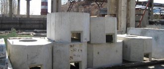
Typical designs of prefabricated reinforced concrete wells
In accordance with nomenclature requirements, the standard classification of KKS has been approved
| Classification by standard size (number or full name) | Maximum load weight, tons | Pass-through type | Corner type | Branch type | Number of input channels |
| 5 | 80 | KKS-5-80 | KKSu 5-80 | KKSr 5-80r | 24 inputs |
| 5 | 10 | KKS 5-10 | KKSu 5-10 | KKSr 5-10r | 24 inputs |
| 4 | 80 | KKS 4-80 | KKSu 4-80 | KKSr 4-80r | 12 inputs |
| 4 | 10 | KKS 4-10 | KKSu 4-10 | KKSr 4-10r | 12 inputs |
| 3 | 80 | KKS 3-80 | KKSu 3-80 | KKSr 3-80r | 6 inputs |
| 3 | 10 | KKS 3-10 | KKSu 3-10 | KKSr 3-10r | 6 inputs |
| 2 | 80 | KKS 2-80 | Not provided | Not provided | 2 inputs |
| 2 | 10 | KKS 2-10 | Not provided | Not provided | 2 inputs |
| 1 | 10 | KKS 1-10 | Not provided | Not provided | 1 input |
| I special | 80 | KKSS – 1-80 | KKSSu-1-80 | KKSSR-1-80 | 36 inputs |
| I special for existing sewer system | 80 | KKSS-1-1-80 | KKSSu-1-1-80 | KKSSr-1-1-80 | 36 inputs |
| II special | 80 | KKSS – 2-80 | KKSSu-2-80 | KKSSR-2-80 | 48 inputs |
| II special for existing sewer system | 80 | KKSS-2-1-80 | KKSSu-2-1-80 | KKSSr-2-1-80 | 48 inputs |
| V for container type NRP | 80 | KKS – 5M-80 | Not provided | Not provided | 24 inputs |
- Please note that in the standard table, the KKS 1-10 series well is not considered.
- Please note that previously sizes from 1 to 5 had a different name according to GOST - small box, large box, small type, medium type, large type.
- Please note that all stationary wells are developed taking into account the technical data for the arrangement of the automatic telephone exchange.
Cable Manhole Configurations
Depending on the direction and number of incoming cable pipeline blocks, wells are divided into the following types:
- Stationary cable wells. Devices of this configuration are most often used for installing cable lines and communications; they are installed directly near stations, points and other nodes for connecting to them with a short section. They are mainly monolithic;
- Walk-through wells are intended for installation in linear sections of laying communications and in areas with a slight angular deviation in the horizontal (within 15 degrees);
- Branching cable wells. This type of cable wells is installed at points where the route of laid communications branches into several directions. Prefabricated branching devices are assembled from standard walk-through and corner reinforced concrete cable wells and represent a complex large-sized structure;
- Corner cable wells. Cable wells of this configuration are installed in places where communications rotate by 90 degrees. When the angular rotation differs from the value of 90 degrees, non-standard design solutions are used with a deviation of the reception of the channel axis on the side of the change in the laying direction.
All reinforced concrete cable wells have mandatory structural reinforcement. It is made of steel reinforcement or mesh, connected using resistance spot welding. All metal elements are coated with an anti-corrosion compound. Reinforcement imparts the overall strength characteristics of the structure and forms the main frame of the product.
Regulatory documentation
Since in recent years there have been changes in the production technology of cable communication wells, regulations have been approved that regulate both the production of CCS and the procedure for installation and operation.
- The main regulations are TU 45.1418-89.
- It is allowed to use the following TU and GOST for previously installed structures - TU-5855-001-92718053-2012.
- The regulatory document allowing the use of the name and other terms for the production of KKS is GOST R 50889-96. In accordance with these regulations, the full name of the KKS is “cable sewer well.”
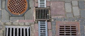
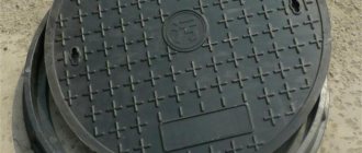
- For the production of KKS hatches, the regulation used is GOST 8591 76.
- To install wells in sewer, gas and water supply networks, the regulation used is GOST 8020 90.
No other technical documentation is provided for the production and operation of sewer wells.
Models of reinforced concrete cable wells
Reinforced concrete cable wells have five varieties and are designated KKS. The first model (KKS-1) has the smallest overall dimensions and weight, KKS-5 is the largest in the series. Models KKS-1 and KKS-2 have a tetrahedral shape, the rest (KKS-3,4,5) have an octagonal configuration. All models are produced both with the installation of internal devices (ruffs and brackets for installing communications and equipment) and without them. The buyer can purchase these structural elements separately (according to the required configuration of communications passing through the cable well) and install them independently.
Reinforced concrete wells KKS - production and application
For the production and technological application of reinforced concrete cable communication wells (CCCs), the unified technical regulations TU No. 45 are used. 1418-83. This regulation determines the standards for the production of KKS, conditions of storage, transportation, installation, etc.
For each type of product, a mandatory labeling condition is provided. The marking indicates the type of product, its structure, size and reinforcement option. In addition, the marking must also indicate the name of the manufacturer, the weight of 1 product, and the date of production.
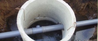
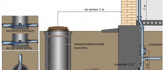
According to typical drawings, a reinforced concrete well has two sections, called the upper and lower sections. Each section has horizontal overlaps. The top section has a hole for mounting a hatch, as well as built-in halves of the side sections. In most cases. There is a requirement for the production of a hatch - the hole must always be exclusively 600 mm in diameter.
On the walls of the structure there are so-called mounting earrings, used for pulling cables and fixing blocks, as well as ruffs used for fastening under equipment.
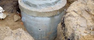
Installation of reinforced concrete cable well
Installation of a cable well (KKS) is carried out in the following order:
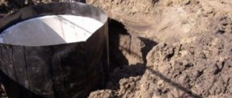
- Excavation and preparation of the excavation for the device;
- Making the basis for installing a sand well, compacting it (manually or mechanically;
- Delivery and unloading of the well (or its elements in the case of a prefabricated structure) into the pit using unloading equipment due to the significant weight of the structure;
- Connecting components using electric arc welding;
- Leveling and fixing the general structure in the pit (depending on the zero level of the top cover of the well);
- Backfilling and compaction of free spaces in the pit;
- Performing the top coating of the well.
About types of wells
As mentioned above, wells are marked KKS from 1 to 5, and each parameter has its own values.
- Type KKS-1, the well has the form of a rectangular slab, size 1030*1050mm. The working height of the well is 78 cm. The upper and lower parts are connected by welding. The upper compartment has a hole for a hatch.
- Type KKS-2, sometimes marked BTK. In assembled version. The well has the shape of an octahedron, having two parts that are hermetically connected to each other. The lower part of KKS-2 is the working bottom of a reinforced concrete structure. There is a hole in the upper part, which is used for mounting the hatch of the LC-GTS series. The total height of the structure of this model range is 1410 mm, the width is 1070 mm, and the working length is 1470 mm.
- Type KKS-3. Sometimes you can find MTK markings. The design has identical similarities with the KKS-2 series. The height of the structure is 1810 mm, length – 2010 mm, width – 1170 mm.
- Type KKS-4. The STK marking is sometimes found in documents. In terms of visual characteristics, the well has similar properties to KKS-2 and KKS-3, but differs in its impressive size. Well height – 2010 mm, width – 1300 mm, height – 1560 mm.
- Type KKS-5. Sometimes the marking TKB is found. The largest type of well, which has dimensions of height - 2010 mm, length - 3030 mm, width - 1560 mm.
Polymer cable manholes
At the present stage of construction of communication routes, plastic cable wells are becoming increasingly popular. In many areas, they began to actively displace their competitors - reinforced concrete cable wells. They have a lot of advantages and advantages:
- Tightness of the cable well chamber;
- Insignificant weight - tens of kilograms, which is significantly less than the weight of reinforced concrete structures;
- Long service life - if the maximum temperature exposure values are observed (no fire, high temperatures, etc.);
- Simplicity and ease of installation - no need to use equipment;
- Low cost;
- Environmental safety of the well material – it does not emit harmful substances into the atmosphere.
Structurally, a polymer (plastic) cable well consists of a polymer shell (chamber) with radial stiffeners, an inspection hole (hatch) and connecting pipes for communications. There are two types of hatch - removable and folding. There are three main types of plastic cable manholes:
- Online access cable well (designated KOD) - most often used when laying fiber-optic telecommunication networks, locating technological connections in the wells, for switching and equipment maintenance. The design of this type of well is made of high-strength polyethylene, is not influenced by negative external factors (corrosion, etc.), and can withstand a temperature range from minus 50 to sixty degrees Celsius above zero without compromising its strength characteristics. It has low weight - only about 17 kg, overall dimensions 1000x800x500 mm;
- Compact cable well for low-pair communications (KKT-1). Mostly used in private housing construction. It has increased strength characteristics due to the presence of stiffeners and can be installed in any area (both on pedestrian sidewalks and roadways). It has overall dimensions of 1920x620x700 mm and a weight of about 25 kg;
- Small-sized wells (KKTM) are intended for installation of cable ducts and are divided into two types: KKTM-1 (overall dimensions are 470x470x450 mm, structure weight 7 kg) and KKTM-2 (product dimensions 600x600x620 mm, weight about 9 kg).
Installation of a plastic cable well
The main stages of installation of a polymer cable well installation:
- The separation of the pit according to the overall dimensions of the well structure installed in it, the volume reserve should be 200 mm in all directions;
- Preparing the base. As a rule, to prevent soil erosion under the well, a concrete foundation is poured rather than sand bedding. In case of installation in places with high vertical loads, the foundation base can be reinforced with steel reinforcement or mesh;
- The well structure is installed and leveled in the pit. These operations can be performed manually, without the use of special equipment;
- The cable well is fixed, backfilled and the free gaps in the pit are compacted;
- The outer surface of the well is covered - either a protective sand-cement blind area is poured, or a concrete road slab is installed.
Telephone wells and equipment for laying communications
The laying of communications, an integral part of which are telephone wells, is carried out using special devices designed to ensure the durability of the structure and the reliability of its operation. The ZHBI-4 plant produces the following components for laying communications:
- Ruffs
- Bolts,
- Consoles,
- Brackets KKP-60 and KKP-130.
You can get acquainted with the prices for telephone wells and components for laying communications on the company’s website, where a detailed price list for products is presented, equipped with detailed images of each item. The above components are used in all models of cable manholes.
Employees of the ZhBI-4 plant will always tell you which components should be chosen for a particular well model and in what quantities. To do this, just contact ]by phone or send a request by email[/anchor].