What is cable ducting?
Among the most used Cable Communications Act terms is not. At the same time, there are valuable clarifications in the Rules for the design, construction and operation of fiber-optic communication lines on overhead power lines, approved by the Ministry of Energy of Russia on December 27, 2002, and the Ministry of Communications of Russia on April 24, 2003. They say that cable drainage is a set of underground pipelines and wells (inspection devices) intended for laying, installation and maintenance of communication cables. There is also such a term as a cable block - this is a cable structure with pipes (channels) for laying cables in them with related wells. The cable block, in fact, is a special case of cable ducting and is also used for laying, installation and maintenance of communication cables. At the same time, you can sometimes hear the phrase “cable structure” - such a structure is specifically designed to accommodate cables and cable couplings. Cable drainage differs from it in that it runs (is laid) underground.
Another document worth noting here is the Regulation on the peculiarities of state registration of ownership and other proprietary rights to line-cable communication structures, approved by Decree of the Government of the Russian Federation of February 11, 2005 N 68. In it, cable sewerage is named as part of line-cable communication structures (LCS ), related to real estate objects, the rights to which are subject to state registration. Moreover, the document allows for the registration of rights not only for each LCS, but also for their totality (association). Taking into account the fact that the legislation contains a new object of civil rights - a unified real estate complex (UNK), the right to cable sewerage as an object of real estate can be registered as part of a larger asset (communication line or even an entire communication network). Therefore, in the documents, the ownership right to the cable duct may not be separately listed, but this does not mean that the operator does not have the right to use and (or) dispose of the property in question.
On a note. Cable sewerage is a complex technical structure (a set of pipelines and wells), inextricably linked with a land plot, and is a real estate object, the rights to which are subject to state registration (Resolution of the Federal Antimonopoly Service of the North-West District dated 02.06.2014 N A21-7123/2012).
Sometimes one of the reasons for the lack of a documented right to use and dispose of cable sewerage is the insufficiently clearly carried out privatization of the property of communication enterprises. Simply put, cable sewerage may not go through the registration procedure in the state property register, that is, it may not end up as a separate item in this register. But the operator has a chance in court to prove his right to cable ducting, which is intended to perform a single production function (providing communication services) - it cannot function separately from the production complex of the enterprise. If the cable duct has not been excluded from the privatized enterprise, then the operator has the right to demand from the Federal Property Management Agency recognition of its ownership rights to this object (Resolution of the Federal Antimonopoly Service of Ukraine dated 04/03/2013 N F09-1219/13).
To make it easier to identify the cable duct, a technical passport of the LKS is filled out for it. It lists the general characteristics of the linear cable communication structure (length or area, number of unattended regeneration and amplification points, number of cable crossings through water barriers, length of cable ducts in kilometers, number of cable inspection devices (telephone wells)). Plus, the owner of the cable duct needs to have at his disposal design and executive accounting and technical documentation (in particular, commissioning acts or other documents indicating the creation (construction) of a line-cable communication structure). An important characteristic will be the location of the cable duct on the territory of a constituent entity (several constituent entities) of the Russian Federation. If a cable duct runs through the territory of several regions, then to identify it, you also need a share (as a percentage) of the total length (length) of the LCS falling on the territory of the corresponding subject of the Russian Federation. The technical passport as an official document also includes information about the state technical registration of LKS. All this is stated in the Instructions for filling out the technical passport of a line-cable communication structure, approved by Order of the Ministry of Information and Communications of Russia dated August 2, 2005 N 90.
Why does an accountant need all this? Then, to have all the necessary information to qualify the cable duct for accounting and tax purposes.
From an accounting perspective
In order to reflect this or that object (asset) in accounting, you need to understand what it includes and how it is used in the organization’s activities. Cable ducting, as indicated above, is one of the types of LCS and is used for the functioning of the communication line as an integral element of the communication network. However, such an element is not provided for by the accounting methodology PBU 6/01 “Accounting for Fixed Assets”. The object of depreciable property can be either a separate cable (telephone sewer), or this sewer with the cable in it, which is already part of the communication line, which can also act as a separate OS object.
Which option should you prefer? According to the author, everything depends on the specific situation. If an organization has laid its own cable in the telephone sewer, then it is advisable to consider them as a single object; if the cable duct provides space for partners’ cables, this indicates that the cable duct should be allocated to a separate inventory facility. After all, what is placed in the cable duct may not belong to the operator and therefore not be reflected on its balance sheet. In addition, if there are your own and someone else’s cables in the sewer at the same time, the operator needs to show this separation in the accounting. Let's explain what was said.
Example 1 . Let’s assume that an organization has put into operation a cable sewer system, having received all the title documents, based on which the cost of the object is 350,000 rubles. The sewer has its own cable, the cost of which is 100,000 rubles. Work on installing (laying) cables into the sewer system is estimated at 50,000 rubles. Let’s say the useful life of a cable duct is 20 years, and that of a cable is 10 years. For the sake of simplicity and clarity, all cost calculations are given without VAT.
The commissioned cable duct and the laid cable are included in the inventory object - a section of the communication line based at the LCS facility. The initial assessment of the object, taking into account installation, is RUB 500,000. (350,000 + 100,000 + 50,000).
It remains to determine the useful life. It is selected based on the indicator of the most durable property - cable duct (20 years), since it is this that constitutes a significant share of the cost of the OS object - part of the communication line. The amount of annual depreciation (if choosing the linear method) will be 25,000 rubles. (RUB 500,000 / 20 years). RUB 2,083 will be depreciated monthly. (RUB 25,000 / 12 months).
How do such systems work?
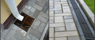
Cable drainage is a kind of buried channels.
Moreover, their depth directly depends on several factors. So, first of all, this is the installation site located at the base of the pipes, as well as the material from which they are made. On average, the laying depth can range from 40 cm to 2 meters.
If these are plastic options, then it is advisable to place them as close to the surface as possible, while concrete ones can be installed even deeper than 2 meters. In this case, the pipes must have a minimum slope. On average, at 10 meters it is no more than 4 cm. This makes it possible to create a natural flow of water if it gets into the channels.
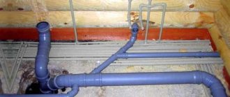
There should be inspection wells every 25-100 meters. Communication between them must go strictly in a straight line. If we talk about the transition to large collectors, as well as the basements of buildings, then in such cases the cables are laid in them along consoles.
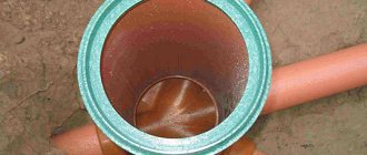
In such a system there can be 2-3 pipes in one trench at the same time. Previously, options with a diameter of 15 cm were used, but now models with a size of 10 cm are considered more optimal. The cable itself is laid directly into them.
Specialist's note: the greater the tension of the pipe, the deeper from the surface it should be located.
https://youtu.be/pD23scnVIgw
Definition, purpose and types of telephone sewer
Telephone cable duct
I would like to start with the fact that telephone sewers are buried structures, which are organized by laying pipes and installing wells.
To be more precise, this is a whole system of underground structures designed to carry cables through them.
The most important purpose of this type of sewer network is to properly protect wires (lead and plastic types) from mechanical damage.
The most important feature of such a pipeline is that there is no need to dig up the soil to protect or repair cables.
Moreover, modern wires laid in telephone sewers are simpler than those located directly in the ground (they are armored).
There are two types of telephone sewer:
- distribution - channels are attached directly to racks, buildings, distribution cabinets, as well as to cable poles. In order for the installation to be competent and there is the possibility of further repairs on the site, special wells are made;
Distribution cable duct
Main cable drainage
What do you need to know about telephone sewer design?
Designing a telephone sewer system is, perhaps, the first stage of the construction of a KKS.
The document must contain the following information:
Cable duct project
- the location of the route for laying the pipeline on the site;
- minimum number of obstacles;
- estimated costs for protecting pipes from electricity;
- the number of mechanisms that are planned to be used during installation.
Design of cable ducts near roads
SNiP provides certain requirements for the installation of telephone sewerage.
Here are some of them:
- the surface of the cable must be smooth, and the pipeline itself must be durable, frost-resistant and resistant to groundwater;
Groundwater resistant cable with smooth surface
PVC pipes 55 and 100 mm in diameter
Cable duct diagram
Laying cable ducts
Cable laying in cable ducts can be carried out in different ways, which depend on its weight.
For example, if it is less than 1500 kg/km, then the installation can be done manually; with a weight of up to 6 thousand kg/km, a cable machine/hand winch is required; if a cable of more than 6000 kg/km is used, there is no need for a winch.
Design rules: norms and requirements, SP
When designing and constructing cable ducts, certain norms and rules must be observed.
Construction standards provide for the following protection methods:
- from electrochemical corrosion,
- from water and gas getting into pipelines and wells,
- from mechanical influences of the soil and ground shifts.
If possible, an impassable part of the road is selected for laying cables to avoid intersections with rail tracks and streets.
A set of design and construction rules has been developed for telecommunication systems of buildings and structures. It regulates all the necessary requirements for laying cables. The Ministry of Communications issued document VSN 116-93 to regulate departmental building standards.
Requirements for installing inspection wells:
- The distance between wells should not be more than 150 m.
- Reinforced concrete wells, prefabricated and fully prefabricated structures are used. Wells made of other materials are used if their use is justified. Recently, ready-made plastic wells with stiffening ribs are often used, especially with a light load.
- To increase the volume, it is allowed to build new wells next to existing ones.
Requirements for laying pipelines:
- The inner surface of the pipeline must be smooth.
- The pipeline must be resistant to frost, physical stress, and waterproof.
- For distribution and main networks, polyethylene pipes with an internal diameter of 55-58 mm are used. In other cases - concrete and asbestos-cement pipes 90-100 mm, or from recycled polyethylene with an outer diameter of 63 and 110 mm.
General norms for laying cables in pipelines:
- Cables of various types can be laid in cable ducts. But no more than 5-6 cables of the same type in one pipe, and they should not occupy more than 0.75 of the channel diameter.
- Armored cables can be laid without polyethylene pipes. Unarmored ones are laid in small cross-section collectors.
- Cables of wired broadcasting networks can be laid together with communication cables if their combined voltage does not exceed 240 V, and the length of the section is controlled.
Temperature requirements:
- Work related to laying cables in a lead sheath in the open air is carried out at a temperature not lower than -20°C.
- The cable is laid in a polyethylene sheath at a temperature of -10°C.
Requirements for placement and method of laying cables:
- If the cables are located in two rows from the passage, then their sequence from top to bottom is as follows: 1 row - wire broadcast cables, communication cables, heat pipes; Row 2 - power cables, wire broadcast cables, communication cables, water pipes.
- When arranged in one row, the sequence from top to bottom is as follows: power cables, wire broadcast cables, communication cables, heat pipes, water pipes.
- Depending on the weight of the cable, a different pulling element is used: steel rope, steel wire, synthetic rope.
Application of cable with copper conductors
The use of a cable with copper conductors requires installation of a galvanic steel stocking on the sealed end of the cable.
It is made to fix the wire workpiece. The copper cable is laid using a certain technology and attached to a drum like a jack.
The cable is fed into the upper part of the drum, and there are polyethylene bushings at the entrance to the channel. The cable tension is constantly monitored.
When installation is completed, the ends are checked for leaks.
Differences between double-wall pipes and conventional pipes
On difficult sections of the route, double-walled pipes are used. They have many advantages over conventional ones.
- High ring rigidity allows it to withstand significant loads (especially for corrugated pipes).
- Despite their rigidity, double-wall pipes are flexible enough to bend around obstacles.
- Withstands temperature changes while maintaining elasticity.
- They have a nylon broach, the length of pipes in coils is from 35 to 150 m.
- The minimum bending radius is 8 diameters.
Installation work
The construction of a telephone sewer begins with marking the route in accordance with the project.
The device can be carried out either in an open way or without disturbing the soil layer.
Before you begin, you need to decide on the boundaries of the trenches and pits for the wells.
By the way, excavation work is carried out by mechanization, and where it is planned to cross communications - manually.
The dimensions of the trench are determined by the number of ditches and the depth of the backfill.
In order for the water that gets into the pipes to drain safely, the bottom of the trench is made at a slope of 3-4 mm/m.
Construction of telephone sewer
Sewer TV inspection
Once installation work has been completed and the sewer is in safe use, internal monitoring may become necessary.
For this purpose, special equipment is used in the form of mini-chambers that can move freely inside the pipes.
The image transmitted to the operator's monitor is saved and can be viewed at any time.
You may need to look at the telephone sewer system to identify any blockages that have formed, identify cracks and damage. You may also need to control illegal cutting into pipes or a banal assessment of completed construction work. Using special equipment, you can always assess the current state of the telephone sewer system and, if necessary, provide technical support without negative consequences.
Telephone sewerage: features of construction and operation
In a large and medium-sized city, communication cables have to be replaced or added quite often. If this was done with excavation of the soil, then the asphalt surface in city centers would have to be changed several times a year. Therefore, communication cables have their own type of sewerage. Despite the unpleasant association, the connected sewer system is in no way connected with the waste sewer system, although it sometimes unwittingly plays the role of a storm drain.
Inconspicuous and incomprehensible to ordinary people, a serviceable connected sewer allows you to tighten the cable without excavation into any multi-storey part of the city. For the last 50 years, the construction project of any apartment building or industrial facility has not been accepted without cable sewerage. Therefore, a connected sewer can be located in places that are quite unexpected for strangers. Over time, it may become unusable due to washout or breaks in canals and wells.
It consists of channels and viewing devices. Channels, for the most part, are built from asbestos-cement pipes with a diameter of 100 mm connected by cuffs, but sometimes you can find block and other types of pipes. In places where it is not possible to lay channels deep enough, steel pipes are used.
Depending on the need, the number of channels also varies. On the outskirts, the sewerage system may contain only 1 channel-pipe, and the exit from a large station may contain 40-50 channels.
Inspection devices are wells, described in more detail in the “SLSMSS Manual” - 3.10 Communication cable duct wells. Usually they are placed at a distance of 50 - 100 meters from each other (acceptable 150 m). In accordance with the sizes, there are 5 main types, according to size: KKS-1, KKS-2, KKS-3, KKS-4, KKS-5. Plus, a well near a large station is usually larger than KKS-5 and is called a station well.
In practice, you can also find “exotics” that cannot be classified under any type; for example, in operation they can install a reinforced concrete ring with a corresponding cover at a channel break
For clarity, I am posting a picture of a cable duct in the center of a small town. The diagram is not drawn according to GOST standards, but it is quite clear. By the way, the scheme is not entirely optimal, but everything is like in life. In a real city, the sewer system is completed at intervals of several years, and some branches are sometimes moved. As a result, parallel directions and dead ends that are incomprehensible to the uninitiated often appear → Funny on the topic.
Approximate layout of communication sewer wells in the center of a small town or microdistrict. Types of wells are indicated in brown. Blue - number of cable channels
Tightening the cable is preceded by pulling a steel wire (usually 3 mm in diameter) into the channel - a workpiece
.
The workpiece is tightened using a device popularly called a molting
(in the “Manual”
channel preparation device
- UZK). In essence, the action of the molting is similar to the cable used to break through blockages in the drain, but it is made more seriously. Instead of a cable, there is a sheathed fiberglass rod up to 150 meters long, which is wound onto a machine reel in the transport position. Tightening of the workpiece is carried out by 3-4 workers, two or three push the line into the channel, one is on duty at the adjacent well and, after the line has passed, feeds the wire.
Laying the pipe package
When there is a natural difference in height in the area, then the pipe package is placed at the same depth along the entire length between the inspection structures, but at a distance of ten meters from the inspection devices, the laying is done with a slope. This is necessary to insert the pipes into the well at the required height. Align the package relative to the horizon using a cord that is pulled along the side border of the ditch.
When laying the package, the pipes are placed along the trench, maintaining a distance of 20-25 millimeters between them. This free space is covered with earth and compacted. The rows of channels in the package must be separated by layers of poured and then compacted soil at least 25 millimeters thick.
The ends of asbestos-cement pipes between the devices are combined using heated polyethylene couplings or cuffs fixed with cement mortar. There is another way of joining, when a metal cuff and resin tapes are used.
If a flexible double-wall pipe for cable ducting is used, it is connected into a package by welding the joints.
Laying copper cable
Cables with a small capacity (such as distribution or intrazone copper cables) with a quantity of no more than 100 pairs are usually tightened manually. In this case, a so-called “stocking” made of galvanic steel is placed on the sealed end of the cable. The workpiece wire is attached to the sleeve or loop at the end. Cable laying is carried out in the following sequence:
- The drum with the cable to be laid must be secured on the side of the receiving device to devices (this can be trestles, carts, etc.). It is fed from the top of the drum.
- At the entrance to the hole, split polyethylene bushings or cable elbows are placed to protect the cable covering from scuffing.
- Having received the appropriate signal from the work performer, the workpiece with the cable connected to it is pulled out in the receiving structure, and at the feeding device they begin to adjust the tension of the cable coming from the drum. After completing installation in the span, the ends of the cable are checked for leaks and laid on the console. Its ends are marked with tags marked A or B.
- It is permissible to lay the cable in the sewer in winter in a polyethylene hose at a temperature of at least 10 degrees below zero, and in a lead sheath - at least minus 20.
Don't miss: Leveling walls with plaster
Laying fiber optic cable
The optical cable is laid in the sewer in the same way as is done with a copper cable. True, there are a number of technological nuances associated with the design of the optical fiber; as a result, it can be stretched over a kilometer-long segment, and in sections with turns, up to half a kilometer long. Since optical fiber is poorly affected by external mechanical loads, it is customary to protect it in sewers with polyethylene tubes with a diameter of 25-63 millimeters. They are pulled into the channel and the cable is placed directly into them. In this case, laying a fiber-optic cable in a sewer is always done using a swivel and with a device for gripping the fiber-optic cable, compensating for its stretching.
What is cable ducting
The network of channels in which cables are laid is equipped with inspection wells that provide access for technical personnel. For cable laying the following can be used:
- pipes;
- trenches;
- tunnels;
- collectors, etc.
The difference between cable ducts and other types is that they are absolutely static, with no movement of liquids or dense particles. Moreover, moisture in any form is dangerous and unacceptable in a cable network trench. This makes it possible to lay the route at shallow depths, without reference to the level of soil freezing. In addition, all requirements for the slope of the trenches are removed, since it does not affect the performance of the cable. The installation of cable ducts and the technology for laying wires depends on their type, purpose, need for maintenance or inspection, and other specific operating features.
Such networks are necessary to protect cables from damage, theft, temperature or atmospheric influences. In addition, the construction of underground trenches makes it possible to free city streets from a huge number of wires that clutter up space and interfere with radio and mobile communications. The canals are constructed in accordance with regulatory requirements, GOST, SNiP and other documents.
Viewing devices
Inspection wells should be installed from each other at a distance of 25-150 m. Wells can be constructed from reinforced concrete rings or bricks. Typically, ready-made reinforced concrete wells are used, which can be either solid or prefabricated. Their sizes and shapes depend on the number of channels passing through the well.
According to their design, inspection wells are divided into the following:
- Walkthroughs. They are installed on straight sections of the sewer system.
- Angular. Wells installed at turns of the sewer route.
- Branching. The well is installed in the approach/outlet areas of the canals.
At buildings where cable equipment is located, station viewing devices must be installed. They are usually made of brick.
Types of cable ducts and their features
The most common type is cable communication, which is used in most areas of human activity:
- government communications;
- warfare;
- Emergency Situations Ministry systems, rescue services, meteorological and synoptic stations;
- scientific and technical organizations, etc.
A communication cable duct is, as a rule, a network of underground communications for laying and servicing telephone wires. Despite the widespread development of wireless technologies, traditional methods have not yet been canceled anywhere, since they are reliable and cannot be destroyed so easily. A telephone channel is a network designed to perform a single task. Unlike other types, where one trench can accommodate different types of cables, telephone networks are low-current and react too strongly to the presence of other wires nearby.
In addition, there are channels for laying fiber optic cable. They are used for high-quality high-frequency communications, high-speed Internet and other types of communications. The cable network is also used to accommodate power lines of different capacities with voltages up to 100 kV. Separate networks can be used to ensure security - trenches with cables for surveillance systems, alarms, warnings, etc.
From a technological point of view, the most common are channels with cables placed in pipes. Such a network allows the development of communication systems without the need for constant excavation work. The cable is pulled into pre-installed pipes, which facilitates maintenance and protects against vibration, mechanical stress, and reduces temperature changes. All cable telephone ducts have such a device. When creating it, the block laying method is widely used, when sequentially connected blocks of several asbestos-cement pipes are laid in a prepared trench and covered with earth. At transitions, changes in direction or height, wells with hatches are installed, from which the network is laid and maintained.
Mounting on brackets
In addition, there are channels where the cable is laid on special brackets located on the side walls. The cross-section must allow movement of technicians performing installation, inspection and maintenance.
Direct laying of cables in the ground is also used, but to a limited extent. As a rule, small subsystems are created in this way in areas where it is impossible to build full-fledged cable channels:
- high groundwater level;
- a large number of other communications, the crossing of which is expressly prohibited;
- it is necessary to ensure passage through water barriers, highways, etc.
All types of cable networks must be created taking into account the standards of water and gas tightness, however, in practice they cannot always be properly observed.
Laying the cable in a trench is cheaper and allows you to operate the system with a higher current load. But there is a constant threat of flooding of areas during a seasonal rise in the level of soil water, with active snow melting or due to heavy rainfall.
Design
The construction of cable ducts, norms, requirements and rules are clearly regulated in the relevant technical documentation. The design of the system should be entrusted to experienced specialists with appropriate qualifications and training. There are specialized organizations that carry out similar work, which are contacted when the need arises to draw up a project for a new network or reconstruction of an existing system.
Creating a project is a very difficult task. In addition to complying with all technology and safety requirements, it is necessary to take into account the possibility of the existence of other communications laid along the route of the trench. In any cases when cable ducting is calculated, design standards require a preliminary survey of the site and the availability of a layout diagram of other underground structures of a similar type.
The calculation is made with some power reserve. The existing system may require an increase in capacity or expansion, which again will require excavation and other activities. This is not always possible and means new labor costs and financial losses, so an increase in capacity is planned immediately, at the design stage. When performing work, they are guided by the requirements of SNiP, relevant joint ventures and other standards. Independent creation of a trench layout, choice of depth and other parameters is fraught with the destruction of other systems with subsequent compensation for damage and the obligation to restore functionality.
Features of double-wall pipes
Double-walled cable duct pipes have high annular rigidity; they are able to withstand impressive mechanical loads, which is especially true for corrugated products. The pipes have good flexibility; with their help you can bypass obstacles along the route.
They can be operated at a wide range of temperatures, and the presence of special accessories allows you to create routes of any complexity. Such pipes for cable ducting can have a length from 35 to 150 m, they are supplied in coils and have a nylon broach. Even at low temperatures they retain elasticity, and the minimum bending radius is 8 diameters.
Installation
Installation of cable ducts is carried out on the basis of a previously created, calculated and approved project. The work is performed in a certain sequence, where each stage is a direct consequence of the previous one. It is impossible to break this sequence. Let's consider the main stages of system installation:
- Preparation . A project is created, materials, trench design and cable laying method are selected. An estimate for the work and specifications for all materials and equipment are created. The terrain is marked using geodetic instruments and techniques;
- excavation . They are carried out based on the type of network, size and specifics of cable installation. In addition, it is necessary to take into account distances, hydrogeological conditions of the site, the presence of other systems and the possibility of expanding the network during subsequent operation. First, they dig a pit for a well, after which they dig trenches;
- cabling . It is either pulled into pipes using special installations, or placed on special brackets on the vertical surfaces of the channel. Direct laying on the ground is possible, but this method is used only in local areas of the system;
- connection, sealing of all parts, backfilling of the trench and sinuses of the well;
- check , system commissioning.
To perform installation work, it is necessary to involve employees of specialized organizations with clearance and appropriate qualifications. It is extremely rare to build a cable network on your own. Because it requires special equipment and knowledge of the technology for performing the work.
Description
The described system is an underground network of containers and channels in which telephone and electrical cables are laid. Such a system may include pipes as well as wells. The former are used for laying wires, while the latter are necessary for inspection, replacement, repair and increasing power.
Cables can be laid openly, without using pipelines; they are replaced by building basements, tunnels and sewers. In this case, the lines are strengthened using special devices.