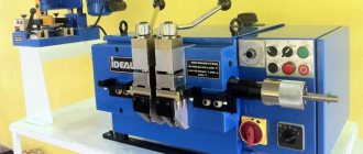
Maintenance of a homemade welding inverter
Drawing of a welding inverter for DIY assembly.
In order for a simple homemade welding inverter to work for a long time, it requires proper care. If the welding equipment breaks down, you need to remove the housing and carefully clean the mechanism with a vacuum cleaner. In parts where it cannot be reached, you can use a brush and a dry cloth.
First of all, for homemade inverters, you need to diagnose all welding equipment - check the voltage, its input and flow. If there is no voltage, it is necessary to monitor the functionality of the power supply.
The problem may also be burnt fuses in the structure. The sensor that measures the temperature, which is not repaired but replaced, is also considered a weak point.
After diagnostics, it is necessary to pay attention to the quality of the connection of the electronic systems of the equipment. Then identify poor-quality fastening by eye or using a special tester
When these problems are identified, they are eliminated immediately using available parts, so as not to provoke overheating and breakdown of all welding equipment.
How the technology works
The method is based on the strong bonding of parts with 2 conductors to which an electrical impulse is applied. This process creates an arc that melts the metal. After the impulse, compression of objects under load is observed.
The welding process proceeds as follows:
- capacitors accumulate the required amount of energy supplied through the primary circuit;
- the electrode contacts the metal, transmitting to it a stream of particles that promote heating and melting;
- the pulse is sent again, the next connection point is formed.
Capacitor welding technology.
The method is effective when working with elements with a thickness of no more than 1.5 mm.
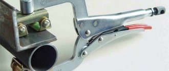
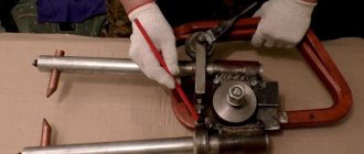
Block design
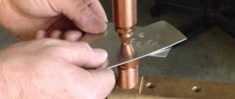
The contact unit is responsible for fixing and moving the rods. The design of a simple block involves attaching a manual sample. More complex options fix the lower one and leave the upper rod movable. The finished structure resembles a vice. A short thin copper rod is fixed here. It should move freely in a vertical plane. Therefore, a screw regulator is installed in the upper part, changing the pressure.
The moving platform and the base of the power unit are isolated from each other. For ease of operation, the device is equipped with a flashlight.
Features of the point method
When using this method, the welding process includes the following steps:
- Preparation of parts. Surfaces are cleaned of dust, rust, and oils.
- Comparison of elements. The parts are installed between the contacts and fixed with them.
- Start the device using the key. The first weld point is formed. Finish the work by removing the electrodes.
- Installation of the rod, supply of an electrical impulse, connection of parts at the next point. Work continues until the desired result is obtained.
Spot welding is a high-tech method of welding parts.
Homemade devices and circuits
DIY devices are often used in home workshops. A minimum area of space is sufficient to carry out the work.
Recommended reading: How to use ultrasonic welding
To assemble devices, 2 types of circuits are used:
- Simple. The device is capable of connecting elements with a thickness of no more than 0.5 mm. In other cases, he fails to cope with the task. The device can be assembled in a home workshop. The principle of operation is based on the issuance of a pulse by a transformer. One end of the winding is connected to the electrode, the other to the workpiece being processed.
- Complex. An electrical circuit includes a large number of functional elements. Assembly will require a lot of time and materials. The finished machine allows you to weld parts with a thickness of 1-1.5 mm.
Further customization
All power elements of the circuit must have high-quality cooling. Transistor switches must be “seated” on thermal paste and a heatsink. It is advisable to use radiators from powerful microprocessors (Athlon). The presence of a fan for cooling in the case is mandatory. The power supply circuit can be modified by placing a capacitor block in front of the transformer. You need to use K78−2 or SVV-81, since other options are unacceptable.
After the preparatory work, you need to start setting up the welding inverter. To do this you need:
- Connect 15V to the PWM, supplying power to the PWM and to the cooling system. Relay K1 acts as a key for closing R11 - with the first response time being about 10 seconds. In addition, C9-C12 is charged, which are discharged through R11. The presence of R11 is mandatory, as it will protect the capacitors from explosion due to a current surge when mains power is supplied.
- Using an oscilloscope, check the board for the presence of rectangular pulses going to the HCPL3120 after K1 and K2 are triggered. In addition, relay K1 must be connected after charging the capacitors. When the inverter is operating without load (idling), the current should be less than 100 mA.
- The correct phase setting of the high-frequency transformer is checked with a 2-beam oscilloscope. To do this, you need to set the PWM frequency to 50..55 Hz and measure the value of U, which should be less than 330 V. The bridge consumption should be 120..150 mA. When the welding inverter is operating, the transformers should not make much noise, and if this happens, you need to figure it out. The noise often occurs due to poorly clamped magnetic circuit plates. Look at the oscilloscope and smoothly turn the variable resistor knob.
- U parameters should not exceed 540 V (345 V is the optimal U value). After measurements, you need to disconnect the oscilloscope and start welding the metal. The welding time should start at 10 seconds and gradually increase it to 5 minutes. If everything is done correctly, there should be no noise.
Thus, knowing the structure and operating principle of an inverter-type welding machine, assembling it with your own hands does not seem to be an impossible task. The homemade version is practically not inferior to the factory one and even surpasses some of its characteristics.
Aluminum electrolytic capacitors in welding inverters
The main components of welding inverters are semiconductor components, a step-down transformer and capacitors. Today, the quality of semiconductor components is so high that if they are used correctly, no problems arise. Due to the fact that the device operates at high frequencies and fairly high currents, special attention should be paid to the stability of the device - the quality of the welding work directly depends on it. The most critical components in this context are electrolytic capacitors, the quality of which greatly affects the reliability of the device and the level of interference introduced into the electrical network.
The most common are aluminum electrolytic capacitors. They are best suited for use in the primary network IP source. Electrolytic capacitors have high capacitance, high rated voltage, small dimensions, and are capable of operating at audio frequencies. Such characteristics are among the undoubted advantages of aluminum electrolytes.
All aluminum electrolytic capacitors are composed of sequential layers of aluminum foil (the anode of the capacitor), a paper spacer, another layer of aluminum foil (the cathode of the capacitor) and another layer of paper. All this is rolled up and placed in an airtight container. Conductors are brought out from the anode and cathode layers for inclusion in the circuit. Also, the aluminum layers are additionally etched in order to increase their surface area and, accordingly, the capacitance of the capacitor. At the same time, the capacity of high-voltage capacitors increases by about 20 times, and low-voltage ones by 100. In addition, this entire structure is treated with chemicals to achieve the required parameters.
Electrolytic capacitors have a rather complex structure, which makes them difficult to manufacture and operate. The characteristics of capacitors can vary greatly under different operating modes and operating climatic conditions. With increasing frequency and temperature, the capacitance of the capacitor and ESR decreases. As the temperature decreases, the capacitance also drops, and the ESR can increase up to 100 times, which, in turn, reduces the maximum permissible ripple current of the capacitor. The reliability of pulse and input network filter capacitors, first of all, depends on their maximum permissible ripple current. Flowing ripple currents can heat up the capacitor, which causes its early failure.
In inverters, the main purposes of electrolytic capacitors are to increase the voltage in the input rectifier and smooth out possible ripples.
Significant problems in the operation of inverters are created by large currents through transistors, high requirements for the shape of control pulses, which implies the use of powerful drivers to control power switches, high requirements for the installation of power circuits, and large pulse currents. All this largely depends on the quality factor of the input filter capacitors, so for inverter welding machines you need to carefully select the parameters of electrolytic capacitors. Thus, in the preliminary rectification unit of a welding inverter, the most critical element is the filtering electrolytic capacitor installed after the diode bridge. It is recommended to install the capacitor in close proximity to the IGBT and diodes, which eliminates the influence of the inductance of the wires connecting the device to the power source on the operation of the inverter. Also, installing capacitors near consumers reduces the internal resistance to alternating current of the power supply, which prevents excitation of the amplifier stages.
Typically, the filter capacitor in full-wave converters is chosen so that the ripple of the rectified voltage does not exceed 5...10 V. It should also be taken into account that the voltage on the filter capacitors will be 1.41 times greater than at the output of the diode bridge. Thus, if after the diode bridge we get 220 V pulsating voltage, then the capacitors will already have 310 V DC voltage. Typically, the operating voltage in the network is limited to 250 V, therefore, the voltage at the filter output will be 350 V. In rare cases, the mains voltage can rise even higher, so capacitors should be selected for an operating voltage of at least 400 V. Capacitors can have additional heating due to high operating currents. The recommended upper temperature range is at least 85...105°C. Input capacitors for smoothing out rectified voltage ripples are selected with a capacity of 470...2500 µF, depending on the power of the device. With a constant gap in the resonant choke, increasing the capacitance of the input capacitor proportionally increases the power supplied to the arc.
There are capacitors on sale, for example, of 1500 and 2200 µF, but, as a rule, instead of one, a bank of capacitors is used - several components of the same capacity connected in parallel. Thanks to parallel connection, internal resistance and inductance are reduced, which improves voltage filtering. Also, at the beginning of the charge, a very large charging current flows through the capacitors, close to the short circuit current. Parallel connection allows you to reduce the current flowing through each capacitor individually, which increases the service life.
What it is
Capacitor contact welding appeared in the 30s of the twentieth century. And since then it has gained wide popularity in various fields of production. During the technology, components from a metal base are seamlessly welded. It occurs due to short-term pulses of electrical energy.
Currently, it is often used in enterprises for welding various small metal elements. Due to the fact that it has a simple technology, craftsmen resort to it at home.
This welding method is often used in repair shops where vehicle body parts are manufactured and repaired. During capacitor welding, during the creation of a seam, there is no burning or deformation of the thin walls of sheets of metal blanks. In the subsequent period, the parts will not require additional straightening.
Capacitor spot welding is used in radio electronics to connect elements that cannot be soldered using conventional fluxes. The equipment is used in the jewelry field for the production and repair of small jewelry elements.
This technology has found application in factories for the production of communication type cabinets. This method is also used in production:
- instruments used in laboratories;
- elements of medical equipment;
- components of equipment used in the food industry.
Varieties
DIY spot welding for batteries
Each of the considered types of CS is used depending on what result is needed.
Capacitor spot welding
The connection of workpieces is carried out at certain points (individual places), this is regulated by GOST 15878-79.
The structure and boundaries of such a point depend on the following parameters:
- geometric surface characteristics of electrodes;
- strength and time of current passed through the point;
- degree of compression of the connected surfaces and their condition.
This type of KS is excellent for working with sheet or profile workpieces, where they overlap each other.
Types of point connections
Roller capacitor welding
Its other name is suture. It is a continuous series of overlapping points. Conductive electrodes in the form of rollers make a seam when overlapping workpieces are rolled through them.
Similar welding is used for the production of various containers: tanks, canisters, vessels, etc.
Diagram of roller welding with a seam section
Capacitor butt welding
Reflow welding with this method is obtained by slowly approaching parts to which current is supplied. When two surfaces come into contact in microcontact zones, explosive melting occurs due to the occurrence of high current density in these places.
Important! The magnetic field pushes the boiling metal out, and squeezing the workpieces promotes the formation of a seam. In this way, parts of complex configurations made of various types of metals are welded together: copper, aluminum, carbon steel
In this way, parts of complex configurations made of various types of metals are welded together: copper, aluminum, carbon steel.
Simple workpieces are spliced using the resistance method, pressing them against each other and passing current through them. As a result, the metals at the point of contact become plastic and sedimentation occurs. Preliminary preparation of contact points is required.
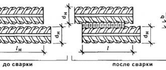
How to weld strips to batteries and connect them together
To connect 18650 batteries to each other, you need to take a metal strip and place it on the battery. In this case, it is better to first tape the batteries to each other with electrical tape or install them in holders. After this, we place the metal tape on the batteries, press the electrodes against it and start the current.
When welding, it should be taken into account that when using a device that delivers high current, it is easy to burn through the metal strip.
Nickel tape comes in different sizes. It is selected according to the current that the load from the batteries will consume. Below we attach a table for selecting the width and thickness of the current tape.
| Width, mm | Thickness, mm | Current value, A |
| 5 | 0,127 | 6 |
| 5 | 0,15 | 8 |
| 6 | 0,2 | 11 |
| 8 | 0,2 | 15 |
| 10 | 0,2 | 18 |
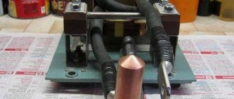
DIY unit assembly diagram
The primary winding is passed through a diode bridge (rectifier) and then connected to a voltage source. The thyristor sends a signal to the bridge diagonal. The thyristor is controlled by a special button to start. The capacitor is connected to the thyristor, or more precisely to its network, to the diode bridge, then it is connected to the winding (primary). To charge the capacitor, an auxiliary circuit with a diode bridge and a transformer is turned on.
A capacitor is used as a pulse source; its capacity should be 1000-2000 µF. To design the system, a transformer is made from a Sh40 type core, the required size is 7 cm. To make the primary winding, you need a wire with a diameter of 8 mm, which is wound 300 times. The secondary winding involves the use of a copper bus with 10 windings. Almost any capacitors are used for the input, the only requirement is a power of 10 V, a voltage of 15.
When the work requires connecting workpieces up to 0.5 cm, it is worth applying some adjustments to the design diagram. For more convenient signal control, use the MTT4K series trigger; it includes parallel thyristors, diodes and a resistor. An additional relay will allow you to adjust the working time.
This homemade capacitor welding works using the following sequence of actions:
- Press the start button, it will start the temporary relay;
- The transformer is turned on using thyristors, then the relay is turned off;
- A resistor is used to determine the pulse duration.
How does the welding process take place?
After the capacitor welding has been assembled with our own hands, we are ready to begin work. First, you should prepare the parts by cleaning them from rust and other dirt. Before placing the workpieces between the electrodes, they are connected in the position in which they need to be welded. Then the device starts. Now you can squeeze the electrodes and wait 1-2 minutes. The charge that accumulates in the high-capacity capacitor will pass through the welded fasteners and the surface of the material. As a result, it melts. Once these steps have been completed, you can proceed to the next steps and weld the remaining parts of the metal.
Before welding work at home, it is worth preparing materials such as sandpaper, grinder, knife, screwdriver, any clamp or pliers.
Carrying out capacitor spot welding
Everything is done in a few simple steps:
- Preparation of products. High-quality riveting will be possible with perfectly clean surfaces. They should be free of dirt, corrosion, foreign mixtures, etc.
- Connecting parts. Here the alloys are placed in the required manner, installed between two contacts and compressed by them. After pressing the start button, the welding procedure begins, and upon completion the electrodes are disconnected.
- Repeat. The second point is repeated until the entire area is securely welded.
The welder will also need auxiliary construction tools: chisel, hammer, compass, knife, emery board, etc. They carry out preparation, alignment and marking of metal. Despite the simplicity of the entire process, the employee is obliged to strictly adhere to safety precautions. Failure to do so may result in electric shock or fire.
Existing types of spot welding
Design of transformers for spot welding.
Sometimes a connection without transformers is used. Capacitors in this case will discharge energy to the connected base. The following charging schemes are allowed:
- 1000 µF devices will accumulate energy for voltages up to 1000 V through a step-up transformer, while the welding time will be 0.005 s. The welding current is in the range from 10 to 100 A. This method is dangerous for humans due to the high voltage.
- 40000-400000 uF devices will accumulate energy at voltages up to 60 V through a step-down transformer. Welding time can reach 0.6 s. in this case, the welding current is in the range from 1000 to 2000 A.
In other cases, welding using transformers is used. In this case, the capacitor will discharge the energy charge to the primary winding of the transformer device.
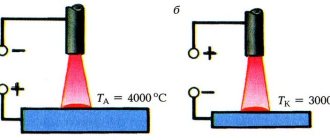
Types of resistance welding: a – butt; b – point; c – roller; 1 – welding seam; 2 – electrode; 3 – parts to be welded; 4 – movable plate with a moving part; 5 – welding transformer; 6 – fixed plate.
The parts to be connected are placed in a welding circuit, which is connected to the secondary winding of the transformer. This connection method is used as microwelding with the following parameters:
- charging voltage – 1000 V;
- welding time – 0.001 s.;
- welding current – 6000 A;
- capacitor capacity – 1000 µF.
The capacitor will accumulate energy to a specific amount when the lever is placed to the left. With the right one, the heat exchangers are discharged onto the primary winding of the transformer structure. The capacitor connection method in the secondary winding is induced by an electromotive force. This force determines the current strength in the welding chain.
Spot welding from capacitors
A simple resistance welder for 18650 batteries can be assembled in an hour. For this we need:
- a transformer, the voltage at the output of the secondary winding is in the range from 15 to 25 V;
- 4 capacitors of 2200 uF rated at 35 V;
- button;
- connecting wires;
- thick copper wire for electrodes;
- 4 diodes for rectifier assembly or diode bridge.
We will assemble the spot welding machine according to the following scheme:
To start working with this device, click on the button. When the capacitors are charged, release the button. After this, we place the strip on the battery and press them with a welding fork. In this case, a short circuit will occur, a large current will flow between the contacts and the metals will be welded to each other.
Step-by-step instructions on how to assemble this device:
- solder the capacitors in parallel to each other;
- We solder the wires coming from the capacitors to two copper wires;
- We put a plastic plug on the wires and glue it so that the wires do not dangle;
- install the plastic tube and place it on the glue.
To make a welding machine more powerful, you need to increase the total capacitance of the capacitors.
Features of application
The welding process using stored energy is recommended for connecting thin rods or wires of different thicknesses.
The spot capacitor welding method is used in the creation of devices and the manufacture of electrical equipment. This type of joint is suitable for joining thick workpieces to thin parts.
In industry, the following work is carried out using the spot welding method:
- fastening bolts, hook-shaped elements, studs of different diameters, and so on;
- connection of elements of clock mechanisms, film and photographic equipment;
- welding of various alloys;
- production of light and optical equipment.
The seam method, which is roller welding, is used to connect vacuum-type electronic devices with membranes. The method allows you to obtain a sealed seam with a continuous structure. This can be achieved by producing a connection with an overlap.
The difference between the spot welding method and other existing ones
Capacitor welding with capacitor discharge through the primary winding of a transformer: a—process diagram; b—current diagram.
We advise you to study Safety precautions when handling electric current
The main difference between this connection method is environmental friendliness. The standard capacitor welding device operates at high currents, making it possible to obtain a seam of excellent quality with low power consumption.
The capacitor welding method, as well as devices for it, are most often used in cases where it is necessary to perform microwelding or connect workpieces of large sections and thicknesses. is as follows:
- Capacitors accumulate energy in the required quantity.
- The charges are converted into heat, which is used for welding.
You should know that spot welding is environmentally friendly, as it has virtually no impact on the environment. The devices used do not require liquid for cooling, since no heat is generated from them. This significant advantage makes it possible to increase the life cycle of the entire device to obtain permanent connections.
Instead of typical cylinders, the designs use special servos, and therefore there is no need for pneumatic connections. Built-in components allow you to accumulate welding force quite quickly and efficiently. The electrodes will act delicately on the base.
Capacitor welding has the following advantages:
- the ability to weld at high speed;
- accuracy of connection of elements;
- high level of environmental friendliness;
- connection reliability;
- durability of welding devices.
Capacitor welding scheme.
Due to the high speed, spot welding will not deform or melt the metal. The devices act on various workpieces in a gentle manner. Excellent quality indicators can be obtained using the contact or impact method of joining workpieces. For example, the shock-capacitor method is best used for joining non-ferrous metals and alloys based on them. As a result, the seam will be aesthetic, reliable, and the process of obtaining permanent connections will take a small amount of time.
Capacitor welding is quite often used in industrial environments due to its combination of performance characteristics. A technological phenomenon is formed during which inseparable contact of metal workpieces occurs due to the release of heat. At the same time, dirt, oxide films, various inclusions and bulges will be removed from the welding site by compression force. As a result, connections will appear between the atoms of the coatings being connected.
Energy charges will be accumulated when charging from a generator or rectifier. Energy can be adjusted by changing the voltage and charging capacity.
Distinctive features
Standard welding involves the use of complex equipment that uses special electrodes. They are applied to the surface being processed, which creates ignition of the winding, leading to melting of the rolled metal. Next, the molten metal flows into the bath, where, after solidification, it holds the elements together. Only an experienced person can handle such a thing, and the gas and ultraviolet radiation released will have a negative effect on the body. It should be noted that this system cannot weld small components.
Capacitor welding does not harm the environment, and after manipulation there are practically no traces of external influences left on the plane. This approach will also save electricity, and the process requires minimal personal protective equipment. The device does not require cooling, and everything will take a minimum of time. A special feature is the high precision and accuracy of the connection. The equipment is compact, and its scope of application is micro-welding and electric welding of large sections.
Varieties
The riveting of both sections occurs due to the strong electrical influence that accumulates in the two-terminal networks, and the process itself is divided into three categories:
- contact implies tight pressing of both workpieces and contact of the electrodes to the required place. As a result of touching, electricity is supplied to a small area of the object, the temperature of which promotes melting and future attachment. Regarding the voltage, it is equal to 15 kA, and lasts for 0.3 seconds;
- impact technology is also designed to connect both elements, however, the supply of electricity is carried out using a short-term impact. The operation time is reduced to 1.5 m/s, which reduces the melting area;
- point technique. In this situation, you will need two copper contacts that touch the object on two sides. The current intensity reaches 10 kA, and the products are bonded at the point of contact.
In the first case, the effect of electric current is applied to the plane of the workpiece, and riveting is carried out by applying a pulse with a force of up to 100 A, and within 0.005 seconds. In certain circumstances, the current can reach 1.2 kA even at a voltage of 60 V. Here the duration is 0.6 seconds.
In the second option, the discharge is produced on the secondary winding, and from it is transmitted to the communication site. Regarding the influence parameters, we can say that it is 1 kV (on the secondary coil 6 kA). The length of all changes is 0.001 s.
Choice of electrolytes from Hitachi, Samwha, Yageo
On the electronics market today you can find a large number of suitable capacitors from well-known and little-known manufacturers. When choosing equipment, one should not forget that with similar parameters, capacitors differ greatly in quality and reliability. The most well-proven products are from such world-famous manufacturers of high-quality aluminum capacitors as Hitachi, Samwha and Yageo. Companies are actively developing new technologies for the production of capacitors, so their products have better characteristics compared to competitors' products.
Aluminum electrolytic capacitors are available in several form factors:
- for mounting on a printed circuit board;
- with reinforced snap-in pins (Snap-In);
- with bolted terminals (Screw Terminal).
Tables 1, 2 and 3 present the series of the above manufacturers that are most optimal for use in the pre-rectification unit, and their appearance is shown in Figures 2, 3 and 4, respectively. The given series have a maximum service life (within the family of a particular manufacturer) and an extended temperature range.
Table 1. Electrolytic capacitors manufactured by Yageo
| Name | Capacity, µF | Voltage, V | Ripple current, A | Dimensions, mm | Form factor | Service life, h/°C |
| LV | 470, 560, 680 | 400, 450 | 1,70; 1,90; 2,10 | 35×40, 35×45, 35×50 | Snap-In | 3000/105 |
| L.C. | 470 | 400, 450 | 1,90; 2,10 | 35×45, 35×50 | Snap-In | 5000/105 |
| N.H. | 470…22000 | 400, 450, 500 | 2,4…39,4 | 51×80…89×270 | Screw Terminal | 5000/105 |
Table 2. Electrolytic capacitors manufactured by Samwha
| Name | Capacity, µF | Voltage, V | Ripple current, A | Dimensions, mm | Form factor | Service life, h/°C |
| HY | 470, 560 | 400, 450 | 1,91; 2,14 | 35×45; 35×50 | Snap-In | 7000/105 |
| JY | 470 | 400, 450 | 1,88 | 35×45 | Snap-In | 10000/105 |
| EY | 1500…10000 | 400, 450 | 6,1…24,3 | 51×110…89×160 | Screw Terminal | 7000/105 |
Table 3. Electrolytic capacitors manufactured by Hitachi
| Name | Capacity, µF | Voltage, V | Ripple current, A | Dimensions, mm | Form factor | Service life, h/°C |
| HP3 | 470…2100 | 400, 420, 450, 500 | 2,75…9,58 | 30×40, 35×35…40×110 | Snap-In | 6000/85 |
| HU3 | 470…1500 | 400, 420, 450, 500 | 2,17…4,32 | 35×45, 40×41…40×101 | Snap-In | 6000/105 |
| HL2 | 470…1000 | 400, 420, 450, 500 | 1,92…3,48 | 35×40, 30×50…35×80 | Snap-In | 12000/105 |
| GXA | 1000…12000 | 400, 450 | 4,5…29,7 | 51×75…90×236 | Screw Terminal | 12000/105 |
| GXR | 2700…11000 | 400, 450 | 8,3…34,2 | 64×100…90×178 | Screw Terminal | 12000/105 |
As can be seen from Tables 1, 2 and 3, the product range is quite wide, and the user has the opportunity to assemble a capacitor bank, the parameters of which will fully meet the requirements of the future welding inverter. The most reliable are Hitachi capacitors with a guaranteed service life of up to 12,000 hours, while competitors have this parameter up to 10,000 hours in Samwha JY series capacitors and up to 5,000 hours in Yageo LC, NF, NH series capacitors. True, this parameter does not indicate a guaranteed failure of the capacitor after the specified line. Here we mean only the time of use at maximum load and temperature. When used in a smaller temperature range, the service life will increase accordingly. After the specified period, it is also possible to reduce the capacity by 10% and increase losses by 10...13% when operating at maximum temperature.
Rice. 2. Yageo electrolytic capacitors
Rice. 3. Samwha electrolytic capacitors
Rice. 4. Hitachi electrolytic capacitors
It is noteworthy that in each series you can find a different configuration of capacitor leads - with reinforced snap-in terminals or bolted terminals. Bolted terminals provide guaranteed reliability of the assembly, and capacitors with latched terminals add to the reliability and ease of installation on a printed circuit board.
Areas of application
Capacitor welding is used not only for welding battery elements, welding fittings, but also for many other works. This is an economical process, which is why it is often used at home. This technology is considered especially in demand when repairing transport bodies.
This type of welding has also found its application in radio electronics when connecting products that cannot be soldered with conventional flux or fail during overheating. Active use of these types of devices is observed during welding and repair of jewelry. An enterprise that sells communication cabinets, equipment for laboratories, the food and medical industries cannot do without capacitors. This type of welding is often used during the construction of buildings, bridges and utilities.
Capacitor type spot welding is used in industry in the following cases.
- When welding bolts, nuts, hooks.
- Connection of metals, not excluding non-ferrous ones.
- Welding elements from watches and photographic equipment.
- The manufacturing process of lighting and optical equipment.
- When assembling electrical equipment.
Technological features
The technology in which the place of contact of two metals being joined is subjected to a mechanical compression force and subsequent heating as a result of passing an electric current is called resistance welding.
contact welding
Capacitor welding (CS) is one of the varieties of such technology using accumulated energy. Its main difference is the short-term supply of current to the junction, due to the discharge time of the capacitors.
Attention! The source of energy for the electric current passing through the contact point is capacitors with a large capacity. Discharging through the welding zone, they melt metals
The time of current exposure to the seam is minimized (up to 3 ms), thereby heating is dosed and maximally targeted at the point of contact. This ensures stable quality of connection of parts at the joints.
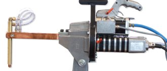
Equipment used
There is a division of installations into transformer and transformerless models. The presence of a transformer allows you to regulate the charge voltage and discharge current. The use of a step-down transformer during discharge increases the welding current.
Transformer-free equipment has its advantages: design simplicity and the possibility of forming a thermal field directly in the contact resistance zone (on the plane). In this case, a current pulse reaching up to 100 A acts on the workpiece for 0.005 s. If necessary, the currents are increased to 1.2 kA (at U = 60 V) and act on the parts for up to 0.6 s.
We advise you to study What voltage should be on the battery
Transformer and transformerless CS circuits
Basic Techniques
The connection of two metals using KS can be done in several ways. These include the following categories of similar technology:
- point - used for mating elements that have a large difference in the thickness of the material (sheet and pin), and is also used for the manufacture of vacuum electronic products and in precision instrument making;
- suture or roller - using this technology, membranes and bellows are connected, rollers serve as contact electrodes, and the connection point is a continuous seam;
- butt - the discharge first melts the ends of the workpieces, then they are pressed (melting method), or current is applied at the moment the surfaces touch (resistance method).
Information. The reflow method requires the presence of a protrusion on the parts being welded. This is a cylinder with a diameter of 0.6-0.8 mm and a height of 0.55-0.75 mm. Such a protrusion allows you to accurately position the welding site and guarantee a stable combustion arc over the entire surface when the capacitor is discharged.
Main advantages
The advantages of CS include the following points:
- strength of the joint;
- low power consumption of units;
- possibility of work automation;
- high productivity with simplicity of the process;
- narrow sector of temperature influence;
- no load surges in the power supply in the presence of high welding currents.
Some disadvantages
The presence of special welding devices and additional equipment, the limit on the use of large sections may well be considered disadvantages of such technology.
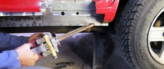
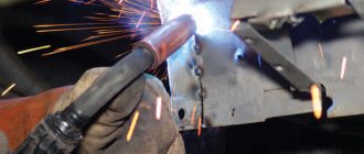
Semi-automatic welding from an inverter
To convert an inverter into a semi-automatic welding machine, you will need three main modules. Electric, providing current from the inverter and welding mode, a mechanism for supplying wire and a torch with a nozzle. The burner creates a gaseous environment in the form of a cloud of protective inert gas that prevents oxidation of the molten metal. For this, a carbon dioxide cylinder is used, which is connected to the device using a hose and an inlet fitting. If you use filler material with a special coating that forms a protective environment, you can do without a cylinder. This method is common among craftsmen.
The torch replaces the electrode holder familiar to welders. Externally, it looks like a pistol grip with a key that provides wire feeding.
It moves along a thin channel passing inside the rubberized sleeve connecting the semiautomatic device to the burner. The channel for supplying gas during welding is located in the same sleeve and ends with a nozzle at the end of the torch.
For high-quality welding, a semi-automatic inverter must maintain a constant voltage at the output, like factory equipment.
Required tools and materials
To create a semi-automatic machine from an inverter with your own hands, you will need to prepare the necessary components and equipment.
List of tools and materials:
- Inverter with output current from 150 A.
- A wire feed mechanism that moves it without jerking or slowing down.
- Gas burner for melting the bath.
- A supply hose that will serve as a guide sleeve for the wire moving towards the work area.
- A gas hose that supplies protective carbon dioxide to the welding site.
- Spool of filler wire.
- Electronics unit for controlling the operation of a semi-automatic welding machine. Here the current strength, voltage and operating speed are adjusted.
- Semi-automatic welding circuit diagram.
Most of the components are used without significant changes. The wire feed mechanism will require modifications so that the process matches the melting speed. The device must be adjustable, because the speed varies depending on the type of materials being welded, the type and diameter of the wire.
Inverter conversion process
In a finished inverter, you first need to remake the transformer included in it. It is covered with an additional layer consisting of copper strip and thermal paper.
Ordinary copper wire cannot be used for a welding transformer. When welding, it overheats greatly and can stop the operation of the entire semi-automatic welding machine.
The secondary winding of the transformer will also require intervention. It is covered in three layers of tin, insulated with fluoroplastic tape. The ends of the applied winding are soldered. As a result of manipulation, the conductivity increases significantly.
An important element is a fan that will cool the device, protecting it from overheating.
An inverter for manual welding can easily be converted into a power source for a semi-automatic machine. A functioning device does not need to be disassembled, but all additional equipment is placed in a separate housing. It houses a freely rotating spool of welding wire and a pulling mechanism. The side panel displays a wire speed regulator and a socket for connecting a hose.
An old computer system case will do just fine. It turns out compact and neat.
The current parameters can be adjusted on the inverter, then the “positive” terminal is connected to the workpiece from it.
The “negative” contact is removed from the inverter and goes into the new housing. Here it is connected to the sleeve terminal. It is important that the welding wire is connected to this potential.
The gas hose running from the cylinder to the burner is also attached to the housing. If you use the valve from a car windshield wiper, the gas supply will be adjusted.
The above arrangement is simple to implement, and the inverter can be simultaneously used for manual arc welding and as a power source for a home-made semi-automatic machine.
Wire feeder assembly
The feed mechanism is necessary for the uniform flow of electrode wire at the required speed into the welding zone.
Consumables are selected based on the type of metal and the purpose of welding work. Material and size may vary. Therefore, the device must be adjustable to suit different types of wire and welding conditions. Running wire diameters: 0.8; 1; 1.2 and 1.6 mm.
The wire drawing mechanism is purchased ready-made in the electrical goods department or made from improvised materials. For assembly you will need a motor from car windshield wipers, three bearings, a pressure spring and a roller mounted on the electric motor shaft. And also plates at least 1 cm thick of a suitable size on which the bearings are mounted.
The components are placed on a textolite plate with a thickness of at least 5 mm. The wire is inserted between the bearing and the roller. The exit location should coincide with the fastening of the end of the supply hose into which it is pulled. The wire is wound evenly and carefully onto the reel, because the quality of the future connecting seam depends on this. The coil is installed on a homemade support and fixed. During operation, the wire will unwind and flow to the joint to be welded. With the help of the feeding mechanism, it is possible to simplify and speed up welding work and make it more productive.
Burner assembly design
A welding torch is a welder’s working tool for making a weld in a protective gas environment. It lasts no more than six months and is considered a consumable item.
The burners operate on the same principle, although they differ in size, materials, maximum temperature, power and gas supply mechanism.
- base with handle;
- nozzle;
- holder;
- tip;
- insulating sleeve.
Welding is accompanied by overheating of the torch elements. The nozzle and current carrying tip suffer the most. The duration of operation will depend on the material of the tip. Copper is widely used, and in more expensive versions, tungsten. The average tip life is 200 hours. They are made quick-change because they have to be changed frequently.
The handle is made of heat-resistant insulating material, which reliably protects the welder from electric shock. On the torch handle, a button controls the on and off supply of consumables and protective gas. A feeding sleeve with a standard length of 2.5–7 m extends from the handle. The choice of sleeve length depends on the type of work performed.
It is not recommended to allow excess sleeves folded into rings. The output coil voltage causes them to become very hot, which can cause a short circuit.
There is a wide selection of gas burners on the market. The models are characterized by the following parameters:
- load current;
- cooling method: air or water;
- the length of the sleeve;
- connection with a plug or Euro connector;
- control method: universal, push-button or valve.
The burner should be compact and lightweight. For a homemade device, a plug connector is sufficient. The plastic case must be durable and ergonomic. The burner is selected according to current parameters that are lower than those of a semiautomatic device.
To ignite the arc, it is necessary that the wire extends beyond the edge of the burner by 10–15 cm.
The supply of consumables is turned on by pressing a button on the torch, which is in the hands of the welder. The toggle switch on the body opens and closes the gas supply to the welding zone.
Control and Power
The semi-automatic device is controlled by a microcontroller. It is also responsible for converting and stabilizing current.
The power supply to the wire pulling mechanism and the valve that turns off the gas is supplied with a voltage of 12 V. To do this, you will need to install a small transformer with a rectifier. Switching between the motor and the valve occurs through a 12 V intermediate auto relay.
Assembly of the unit
The assembly instructions will help you make a quality semi-automatic welding machine. The work is carried out in the following sequence:
- Connect the inverter to power and control devices.
- Thread the wire into the feed mechanism and check for smooth movement.
- Set the required wire feed speed.
- Connect the burner to a hose, which is connected to the feeder.
- Connect a gas cylinder with a reducer and a pressure gauge to the burner.
- Turn on the inverter and feeder.
- Check the flow of gas and wire. After gas supply, the delay in wire movement should be 1–2 s. It enters a ready-made protective environment, otherwise it will stick.
When preparing a home-made semi-automatic machine for the first start-up, you need to take care of cooling the assembled semi-automatic welding machine so that it does not overheat. For this purpose, input and output rectifiers and power switches are mounted on radiators. On the inverter body where the radiator is located, that is, in the most heated zone, it is recommended to install a temperature sensor that will de-energize the device if it overheats.
After this, connect the power part to the control unit, and then turn on the semi-automatic device to the power supply. When the mains lights come on, the inverter needs to be tested. At the output of the device, a current is measured, which should not exceed 120 A. If its value is less, this means that a voltage below 100 V is supplied to the equipment through the wires. In this case, the current is changed and the voltage is controlled, achieving the desired parameters. In this case, the inverter should not overheat.
Under load, the semi-automatic device is checked as follows. The welding wires are connected to a rheostat designed for a current of 60 A and a resistance of at least 0.5 Ohm. The current supplied to the burner is controlled with an ammeter. If the current strength differs from the norm, change the resistance value.
After turning on the assembled semi-automatic device, the indicator should show a current strength of 120 A. This figure confirms the correctness of the work. If eights are displayed, then the reason is insufficient voltage in the supply wires. Welding inverters operate in the operating current adjustment range of 20–160 A.
Control during work
The performance and service life of the semi-automatic device depends on compliance with the temperature regime. The normal temperature on radiators is 75 °C. When overheating, breakdown or short circuit occurs, a sound signal appears. The electronic control unit will automatically reduce the operating current to 20 A, the sound signal will remain until the situation stabilizes. An error in the system is accompanied by the Err code on the indicator.
How to make a device for spot welding with your own hands?
Seam welding diagram.
You can easily assemble a device for welding copper wire yourself. To do this, you should purchase a 450 W transformer. The transformer is needed of a standard type, with a primary copper winding 0.75x2 mm thick and a secondary winding with a 6 mm aluminum power cable. In this case, you will also need a carbon electrode.
The device for welding copper wires operates on alternating current from 35 to 40 A. The highest voltage point is 15 V. Several clamps can be used as an electrode holder. The conductor for the manufactured device can be a carbon electrode, which is made from a trolleybus contact brush.
If you use this device carefully, it can last for several years. You need to monitor the contacts and also ensure that the battery does not discharge. The welding scheme for copper wires does not imply the use of devices with high resources. A homemade device can perfectly cope with significant amounts of work.
It should be noted: welding work in this case can be automated, which is a significant advantage.
Semi-automatic welding transformer
An old welding transformer that has been gathering dust in the garage for a long time can be turned into a working semi-automatic welding machine.
An old device with a rectifier and a direct current output does not need to be modified. If the transformer was used for AC welding, it will have to be improved.
Current conversion block
Installing a filter and a diode bridge will help convert the transformer into a direct current source. The diode assembly serves to rectify the secondary voltage, and the filter ensures a stable arc by smoothing out ripples.
After rectification, the voltage takes the form of a sinusoid and is a pulsating voltage with a frequency of 100 Hz. A zero value is noted twice during the period. If it is used in its existing form, the arc will burn unstably, which will negatively affect the welding process. Connecting a filter will smooth out existing voltage dips.
Filter connection
The filter includes a series choke in the welding circuit and a parallel capacitor. This combination of capacitance and inductance is called an L-shaped filter, which is associated with the representation of the connection of the elements in the diagram.
The capacitor for the semi-automatic device is polar, electrolytic. The capacity must be at least 10 thousand microfarads, and more is only better. To ensure a reserve, the capacitor voltage must be from 100 V. The capacitance of capacitors soldered in parallel is summed up, so you can take existing ones with a lower rating.
Throttle assembly
The choke is obtained by winding an old transformer of suitable dimensions. For these purposes, a supply transformer with a power of at least 250 W, removed from an old tube color TV, is suitable. It typically has two coils on a closed, two-piece oval core. The structure should be disassembled, the leads removed and the coils removed.
For winding you will need a flat copper busbar of a suitable cross-section. Instead of the removed wire, a tire is manually wound onto each of the coils in two layers. The result should be 15–20 turns. The core halves are folded, and a 1.5 mm thick PCB gasket is inserted between them. The coils are returned to their place and connected in series.
To carry out welding work, the assembled semi-automatic machine will require a torch, a wire moving device, a wire feeding hose and carbon dioxide.
The order of further actions for the manufacture of a welding machine
We remove all secondary winding from the coils
It is important not to damage the primary. We number each coil we create.
You need wires for a DIY welding machine. To do this, we wrap the middle coil with a wire taken from the winding. For every 30 laps we perform a dozen taps. We fill both coils, which are located at the edges, with a multi-core cable.
Let's make a terminal. We use a copper pipe with a diameter of 10 millimeters - one side is compressed. The second one needs to be flattened and drilled. It will be needed for fastening.
We replace the fasteners on the transformer with more powerful ones and fasten the terminals. We make a board for the software. It is made of textolite. There should be ten holes, and fasteners are inserted into each.
The resulting welding machine can be powered by 220 volts. To do this, at the end of the process, the windings from the edges are connected in parallel. The middle one is also connected to this circuit in series. The taps are installed in the terminals of the manufactured board. The current is controlled by terminals.
You can make a welding machine in other ways. For example, it is well known that a welding machine is made from car batteries. To do this, take several batteries and connect them in series.
When combining batteries, you need to use very reliable clamps.
This type of welding machine will come in handy in field conditions. You can quickly create it yourself. Even used batteries (inoperative) can be used.
You need to remember that batteries heat up quickly, so you won’t be able to use them for very long. In addition, we must not forget that under increased loads, electrolyte and liquid quickly evaporate from them.
Due to the rechargeable batteries, a rather practical feature is that such a device can be charged overnight. In the morning it will be ready for use.
Soyer condenser mount
The heat into which the energy stored in the capacitor bank is converted is released during the welding process through the protruding tip of the base of the welding fastener, while the tip of the hardware melts and quickly evaporates, creating a cloud of plasma between the fastener and the material to which it is welded.
Thus, a distinctive feature of fasteners for capacitor discharge welding is the presence of a precisely calibrated ignition tip, the correct geometry of which largely determines the result of welding hardware.
First-class hardware for capacitor discharge welding, as well as equipment for working using this technology, is produced by Heinz Soyer Bolzenschweisstecnik GmbH. Soyer's own production facilities allow it to produce a full range of fasteners that comply with the European standard DIN EN ISO 13918.
All stages of the hardware production process are subject to strict control, so the entire range of threaded and non-threaded studs, threaded bushings, insulating nails, grounding contacts and other Soyer products meet the highest quality standards.