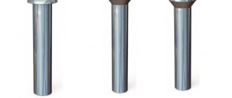
A bolt is a connecting element that has a head, a rod, part of which is smooth, and the other has a thread for screwing on a nut. The smooth part of the “correct” bolt should have a length 2-3 mm shorter than the thickness of the metal structures being connected. Also, washers are used in the connections to ensure better fixation of the nut.
To connect building metal structures, bolts of coarse, normal and high precision, as well as high-strength, self-tapping and foundation or anchor bolts are used.
Connections in metal structures
Connections in structures serve to transfer forces from one element to another. For example, load-bearing steel structures use welded, bolted and riveted connections. In the early periods of the use of steel structures in construction, the main fasteners were rivets. It has long been known that rivets that were installed hot tended to introduce compressive axial forces into the joint. However, this axial force could not be controlled and its magnitude could vary significantly from rivet to rivet. Therefore, this axial force could not be assessed and regulated during design.
In the 1930s, it was first proposed to use high-strength steel bolts in load-bearing steel structures instead of rivets. It was found that such bolts could be tightened sufficiently to prevent slippage in structural joints—something that "hot" steel rivets provided. In the 1970s, the use of preloaded high-strength bolts in non-slip steel connections instead of rivets became widely used throughout the world [1].
In aluminum structures, the limited strength and ductility of structural aluminum alloys must be taken into account when designing connections. For bolted connections involving frictional forces, the transmission of forces through the connection can be negatively affected by the relaxation processes that occur in aluminum. In addition, aluminum structures typically use stainless steel bolts rather than high-strength carbon and alloy steel bolts to avoid the risk of corrosion [2].
Connections of thin-walled structures—steel and aluminum—have their own characteristics compared to thick-walled ones [3].
Bolted connections in steel load-bearing structures
Connections in structures serve to transfer forces from one element to another. For example, in steel structures, welded, bolted and riveted connections can be used in connections, but bolted connections are most often used. The main advantages of bolted connections are:
- simplicity and ease of connection;
- ease of use in construction conditions;
- the ability to adjust and align structural elements.
Assessing the effectiveness of a bolted connection is quite difficult. The stress distribution in the connection and the forces in the bolt depend on both the stiffness of the bolt itself and the stiffness of adjacent steel elements. Therefore, it is believed that an accurate theoretical analysis cannot be performed for a bolted connection. The design of bolted connections is semi-empirical, namely, based on positive practical experience, but always with a confirmed statistical assessment of test results [2].
2.1. Main characteristics of bolts
The strength classes of bolts that are used in structural steel connections are shown in Table 1. All of these bolts are typically used in connections that are subject to static forces and moments. In connections that are subject to fatigue loading, high-strength bolts of strength classes 8.8 and 10.9 are used to ensure the necessary frictional adhesion.
Table 1 - Strength properties of construction bolts
The weakest section of any bolt is its threaded part. The strength of a bolt is usually calculated using the so-called tensile stress area, also called the resistant area. This area is determined by the diameter dres, which is the average of the minimum diameter of the thread at its bottom dn and the maximum diameter at the crest dm, as shown in Figure 1.
The dimensions of any bolt are determined by its nominal diameter, length under the head and thread length.
Figure 1 - Cross section of a bolt and area of tensile stresses
2.2. Three main types of bolted connections
The ultimate strength of bolted connections is assessed based on the adoption of certain simplifications for the redistribution of internal forces in them. It is therefore believed that when a load is transferred through a connection, a bolt may behave as:
1) The bolt takes the entire load on itself. This means that the movement of the plates being connected is limited primarily by the bolt shank;
2) Connection with friction clutch, which is provided by the frictional force created by the axial tension of high-strength bolts. This tension occurs when the bolts are tightened and is at least 70% of the yield strength of the bolt material.
3) Bolts under tensile load.
Figure 2 - Components of forces in various types of connections:
1) a connection in which the bolt takes the entire load,
2) connection with a given tightening of high-strength bolts,
3) axial tensile loading.
2.3. Bolt Load Connection
A bolt that is loaded primarily with static loads should simply be tightened with a spanner-tight. The tightening of such a bolt is achieved by an ordinary person using a regular wrench. This tightening is sufficient to produce a small frictional force between the connected parts and sufficient to transfer a small load without slipping in the connection. As the load on the connection increases, this friction is overcome and irreversible slippage occurs, which occurs due to the presence of a gap between the bolt and the plate. If the load is further increased, there will first be an elastic displacement until plastic deformation begins either along the bolt shaft or along the plate. In addition, plastic deformation can begin simultaneously in both the bolt and the plate.
2.4. Slip Resistant Connections
In the event of repeated loading, the high strength bolts in the connection should be tightened to at least 70% of their tensile strength. When this method of joining is used, the load is transferred through the joint primarily by friction between the fastened parts rather than by shear of the bolts. The strength of such connections depends on the coefficient of friction between adjacent surfaces and the pressing force provided by high-strength bolts. If, when tightening a high-strength bolt of strength class 8.8, the bolt head or washer slips, then one high-strength washer is placed under the slipping element (bolt or nut). In a similar case, for a bolt of strength class 10.9, high-strength washers are placed under both the bolt head and the washer.
The tensile force in a high-strength bolt during installation is controlled by one of the following methods:
1) Torque control method. A special device is used. 2) The “turn the nut” method. Rotate the nut through a certain angle after achieving normal hand tightening. Depends on the thickness of the connection package and washers. 3) Tension indication method, for example, with a special washer. 4) A combination of methods 1) and 2).
Bolted connections and welding of metal structures: which option is better for the installation of structures
Construction from metal structures has successfully proven itself in almost all areas of business, allowing you to quickly, efficiently and relatively inexpensively build reliable, durable areas for organizing activities. The installation of buildings from such structures is based on the method of bolting and welding of metal structures, thanks to which individual elements take the form of a full-fledged functional structure.
Despite the fact that in addition to welding and bolting of metal structures, fastening based on rivets and soldering also takes place, the presented options are still the most popular and most often used due to their advantages and connection technology.
Bolted connection of metal structures
A bolted connection is one of the best fastening options, which simplifies assembly and reduces the duration of installation work. Isn’t that why 95% comes from this type of connection?
Depending on the design solutions and the magnitude of the loads, connecting metal structures with bolts can be carried out using coarse, normal and high-precision hardware.
Bolt holes are made with a diameter larger than the diameter of the bolt by 2-3 mm.
But with this installation technology, the risk of deformation of the connections increases, which is why it is so important to ensure accurate alignment of the fastening holes of the metal structures.
The use of high-strength bolts for metal structures replaces rivets with great efficiency and can be used instead of high-precision bolts. In addition, this type of fastening combines ease of installation, low percentage of deformation and high level of load-bearing capacity.
Preparation for installation using the bolt method includes several stages:
- preparatory stage of joining surfaces;
- joining bolt holes;
- screeding of joint elements;
- drilling holes for installing bolts.
Before tightening the bolt, the structure is aligned. The length and diameter of the bolts are calculated taking into account the specifics of the project.
Types of bolted connections
For the installation of metal structures, several types of bolts are used, the main ones include:
- high-precision bolts made of high-strength galvanized steel;
- rough precision - made with a diameter of up to 20 mm from carbon steel;
- increased accuracy – hardware diameter up to 48 mm, length up to 300 mm.
Fastening metal structures with bolts can be divided according to manufacture:
- overlap;
- using an overlay.
For bolted connections, the most important parameters are:
- bolt accuracy class;
- type of execution;
- bolt parameters (thread pitch, material of manufacture, thickness, etc.).
Advantages of bolted metal structures
Element-by-element assembly of metal structures with bolts is applicable in cases where welding is impossible or the design features of the project do not require this installation method.
The main advantages of a bolted connection include the possibility of repeated assembly and disassembly without loss of performance qualities of the building frame. But besides this they also distinguish:
- low metal consumption and ease of assembly;
- simplified logistics, since prefabricated steel structures are easier to transport;
- the ability to quickly replace individual structures that have failed.
The disadvantage of this type of connection is its geometric limitation due to the fact that the surfaces of the structures being connected must coincide with the holes for the bolts.
Welded connection of metal structures
Manufacturing metal structures by welding is a cost-effective method used in working with metal products. It provides reliable connections of metal structures with a long service life.
The technology of welding metal structures largely affects strength, reliability and price, and therefore one or another welding option is used separately for a specific case.
Types of welding
For the manufacture of welded metal structures, the following types of welding are selected:
- semi-automatic welding;
- spot welding (one of the most financially expensive);
- multi-spot welding.
A significant difference between different types of welding of metal structures lies in the specifics of the current flow to the electrode.
With a point method, the current is supplied to each electrode separately, which requires the use of expensive equipment.
With multipoint, current is supplied to all electrodes using an energy distributor and requires highly qualified specialists.
Advantages of welding metal structures
The main advantages of this method include:
- seam tightness, eliminating the possibility of moisture penetration between the joints of metal structures;
- variability – the ability to connect elements of any shape and in different positions;
- low price of welding metal structures - one of the cheapest methods of fastening due to the absence of the need to use fasteners.
The disadvantages of welding metal structures include susceptibility to corrosion due to local heating. Also, welded structures cannot be dismantled for subsequent assembly, and their connection requires special tools and specialist experience.
Fasteners in load-bearing aluminum structures
3.1. Types of connections in aluminum structures
In load-bearing aluminum structures, the most common mechanical fasteners used are bolts, either aluminum or steel. Solid rivets may be used in some cases, but are now considered obsolete and uneconomical. At the same time, in thin-walled structures, steel and aluminum, special rivets of various designs are widely used, for example, the so-called blind rivets (see section 4).
Compared to welded joints, mechanical fasteners have the advantage that when used for aluminum structures there is no loss of strength due to heat. Moreover, mechanical fasteners are easily applied directly on the construction site, while welding is a factory operation. Therefore, for load-bearing aluminum structures, bolted connections are the main ones.
European rules for making connections in load-bearing aluminum structures are set out in Eurocode 9 (Eurocode 9: Design of aluminum structures - Part 1-1: General structural rules).
3.2. Aluminum bolts
Aluminum bolts have one advantage over steel bolts. They do not change the tightening of a bolted connection with changes in temperature due to thermal expansion, as can happen with steel bolts. The material of the aluminum bolts must match the material of the components being connected.
The following important points must be kept in mind when working with aluminum bolts on aluminum structures:
- Excessive pressure on the aluminum surface when tightening a bolted connection can be avoided by installing high-strength aluminum alloy washers under the head and nut.
- When bolts are loosened and tightened again, the threads in the aluminum component or the aluminum bolt itself quickly wear out. In such cases, it is recommended to use inserts, as shown in Figure 3.
- In connections that are exposed to moisture, the bolts must be sealed.
Figure 3 - Threaded inserts for thin-walled connections
3.3. Steel bolts in aluminum structures
Steel bolts in aluminum structures that are exposed to outdoor climates and other corrosive environments must be protected against corrosion. For example, steel bolts may be zinc coated, electroplated, or hot-dipped. However, any zinc coating has a very short service life. Therefore, it is becoming increasingly common to use stainless steel bolts in aluminum structures. To avoid excessive surface pressure, steel bolts are usually installed with steel washers, both under the bolt head and under the washer.
3.4. Aluminum solid rivets
When solid aluminum rivets are used in load-bearing aluminum structures (Figure 4), they are installed in a cold state. Unlike hot-set solid rivets, cold-set solid rivets do not shrink in size and therefore do not force the sheets or profiles being joined together. This means that cold set rivets are loaded in the joint in the same way as non-tension controlled bolts (see section 2).
Figure 4 - Shapes of solid rivet heads:
a - standard, b - hidden, c - round, d - flat
See more: Rivets in construction
buildingbook.ru
Steel structures on a construction site are almost always connected using a bolted connection and it has many advantages over other connection methods and, above all, welded connections - ease of installation and quality control of the connection.
Among the disadvantages, one can note a higher metal consumption compared to a welded joint because In most cases, overlays are needed. In addition, the bolt hole weakens the section.
There are a great many types of bolted connections, but in this article we will consider the classic connection used in building structures.
Regulatory documents and recommended literature on bolted connections
SNiP II-23-81 Steel structures
SP 16.13330.2011 Steel structures (Updated edition of SNiP II-23-81)
SNiP 3.03.01-87 Load-bearing and enclosing structures
SP 70.13330.2011 Load-bearing and enclosing structures (Updated edition of SNiP 3.03.01-87)
STO 0031-2004 Bolted connections. Range and areas of application
STO 0041-2004 Bolted connections. Design and calculation
STO 0051-2006 Bolted connections. Manufacturing and installation
Types of bolted connections
By number of bolts: single-bolt and multi-bolt. I think there is no need to explain the meaning.
According to the nature of the transfer of force from one element to another:
Not shear-resistant and shear-resistant (friction). To understand the meaning of this classification, let’s consider how a bolted connection generally works when working in shear.
As you can see, the bolt compresses the 2 plates and part of the force is perceived by friction forces. If the bolts do not compress the plates strongly enough, then the plates slip and force Q is perceived by the bolt.
The calculation of non-shear-resistant connections implies that the tightening force of the bolts is not controlled and the entire load is transmitted only through the bolt without taking into account the friction forces that arise. This type of connection is called a connection without controlled bolt tension.
Shear-resistant or friction joints use high-strength bolts that tighten the plates with such force that the load Q is transferred through frictional forces between the 2 plates. Such a connection can be frictional or friction-shear; in the first case, only friction forces are taken into account in the calculation; in the second, friction forces and the shear strength of the bolt are taken into account. Although the friction-shear connection is more economical, it is very difficult to practically implement it in a multi-bolt connection - there is no certainty that all the bolts will simultaneously be able to bear the shear load, so it is better to calculate the friction connection without taking into account the shear.
For high shear loads, a friction connection is more preferable because The metal consumption of this compound is less.
Types of bolts by accuracy class and their application
Bolts of accuracy class A - these bolts are installed in holes drilled to the design diameter (i.e. the bolt fits into the hole without clearance). Initially, the holes are made of a smaller diameter and gradually drilled out to the desired diameter. The diameter of the hole in such connections should not be more than 0.3 mm larger than the diameter of the bolt. It is extremely difficult to make such a connection, so they are practically not used in building structures.
Bolts of accuracy class B (normal accuracy) and C (rough accuracy) are installed in holes 2-3 mm larger than the bolt diameters. The difference between these bolts is the bolt diameter error. For bolts of accuracy class B, the actual diameter can deviate by no more than 0.52 mm, for bolts of accuracy class C up to 1 mm (for bolts with a diameter of up to 30 mm).
For building structures, bolts of accuracy class B are usually used because in the realities of installation on a construction site, achieving high accuracy is almost impossible.
Types of bolts by strength and their application
For carbon steels, the strength class is indicated by two numbers separated by a dot.
There are the following bolt strength classes: 3.6; 3.8; 4.6; 4.8; 5.6; 5.8; 6.6; 8.8; 9.8; 10.9; 12.9.
The first number in the bolt strength classification indicates the tensile strength of the bolt - one unit indicates a tensile strength of 100 MPa, i.e. the tensile strength of a bolt of strength class 9.8 is 9x100=900 MPa (90 kg/mm²).
The second digit in the classification of the strength class indicates the ratio of the yield strength to the ultimate strength in tens of percent - for a bolt of strength class 9.8, the yield strength is equal to 80% of the ultimate strength, i.e. the yield strength is 900 x 0.8 = 720 MPa.
What do these numbers mean? Let's look at the following diagram:
Here is a general case of tensile testing of steel. The horizontal axis indicates the change in the length of the test sample, and the vertical axis indicates the applied force. As we can see from the diagram, with increasing force, the length of the bolt changes linearly only in the area from 0 to point A, the stress at this point is the yield strength, then with a slight increase in load the bolt stretches more strongly, at point D the bolt breaks - this is the strength limit . In building structures, it is necessary to ensure that the bolted connection operates within the yield strength.
The strength class of the bolt must be indicated on the end or side surface of the bolt head
If there are no markings on the bolts, then most likely these are bolts of a strength class below 4.6 (their markings are not required by GOST). The use of bolts and nuts without markings is prohibited in accordance with SNiP 3.03.01.
On high-strength bolts, the symbol of the melt is additionally indicated.
For the bolts used, it is necessary to use nuts corresponding to their strength class: for bolts 4.6, 4.8, nuts of strength class 4 are used, for bolts 5.6, 5.8, nuts of strength class 5, etc. You can replace nuts of one strength class with higher ones (for example, if it is more convenient to assemble nuts of the same strength class for an object).
When bolts are used only for shearing, it is allowed to use the strength class of the nuts with the bolt strength class: 4 – at 5.6 and 5.8; 5 – at 8.8; 8 – at 10.9; 10 – at 12.9.
For stainless steel bolts, markings are also applied to the bolt head. Steel class - A2 or A4 and tensile strength in kg/mm² - 50, 70, 80. For example A4-80: steel grade A4, strength 80 kg/mm² = 800 MPa.
The strength class of bolts in building structures should be determined according to Table D.3 SP 16.13330.2011
It is recommended to use stronger bolts to reduce its diameter and, accordingly, weaken the section less.
Selecting a bolt steel grade
The steel grade of bolts should be assigned according to Table D.4 SP 16.13330.2011
Selection of bolt diameter for building structures
For connections of building metal structures, bolts with a hexagonal head of normal accuracy in accordance with GOST 7798 or increased accuracy in accordance with GOST 7805 with a large thread pitch of diameters from 12 to 48 mm should be used, strength classes 5.6, 5.8, 8.8 and 10.9 in accordance with GOST 1759.4, hex nuts of normal accuracy in accordance with GOST 5915 or increased accuracy according to GOST 5927 strength classes 5, 8 and 10 according to GOST 1759.5, round washers for them according to GOST 11371 version 1 accuracy class A, as well as high-strength bolts, nuts and washers according to GOST 22353 - GOST 22356 diameters 16, 20 , 22, 24, 27, 30, 36, 42 and 48 mm.
The diameter and number of bolts are selected to ensure the required strength of the assembly.
If significant loads are not transmitted through the connection, then M12 bolts can be used. To connect loaded elements, it is recommended to use bolts from M16, for foundations from M20.
It is not recommended to use connections in which the total thickness of the elements being connected exceeds:
for M12 bolts - 40 mm;
for M16 bolts - 50 mm;
for M20 bolts - 60 mm;
for M24 bolts - 100 mm;
for M27 bolts - 140 mm.
Bolt hole diameter
For bolts of accuracy class A, the holes are made without clearance, but it is not recommended to use such a connection due to the great complexity of its manufacture. In building structures, as a rule, bolts of accuracy class B are used.
For bolts of accuracy class B, the hole diameter can be determined using the following table:
Bolt spacing
Distances when placing bolts should be taken according to table 40 SP 16.13330.2011
At joints and assemblies, the bolts must be placed closer to each other, and the structural connecting bolts (which serve to connect parts without transferring significant loads) at maximum distances.
It is allowed to fasten parts with one bolt.
Selecting Bolt Length
We determine the length of the bolt as follows: add up the thicknesses of the elements being connected, the thicknesses of the washers and nuts, and add 0.3d (30% of the bolt diameter) and then look at the range and select the nearest length (rounded up). According to building codes, the bolt must protrude from the nut by at least one turn. It will not be possible to use a bolt that is too long because... There is thread only at the end of the bolt.
For convenience, you can use the following table (from the Soviet reference book)
In bolted shear connections, with a thickness of the outer element up to 8 mm, the thread must be located outside the package of elements being connected; in other cases, the bolt thread should not go deeper into the hole by more than half the thickness of the outer element on the nut side or more than 5 mm. If the selected bolt length does not meet this requirement, then the bolt length must be increased so that this requirement is met.
Here's an example:
The bolt works for shear, the thickness of the fastened elements is 2x12 mm, according to the calculation, a bolt with a diameter of 20 mm, a washer thickness of 3 mm, a spring washer thickness of 5 mm, and a nut thickness of 16 mm are assumed.
The minimum bolt length is: 2x12+3+5+16+0.3x20=54 mm, according to GOST 7798-70 we select an M20x55 bolt. The length of the threaded part of the bolt is 46 mm, i.e. the condition is not satisfied because the thread should go no more than 5 mm into the hole, so we increase the length of the bolt to 2x12+46-5=65 mm. According to the standards, you can accept an M20x65 bolt, but it is better to use an M20x70 bolt, then all the threads will be outside the hole. The spring washer can be replaced with a regular one and another nut can be added (this is very often done because the use of spring washers is limited).
Measures to prevent loosening of bolts
To ensure that the fastening does not loosen over time, it is necessary to use a second nut or lock washers to prevent the bolts and nuts from unscrewing. If the bolt is in tension, then a second bolt must be used.
There are also special nuts with a locking ring or flange.
It is prohibited to use spring washers for oval holes.
Installing washers
No more than one washer should be installed under the nut. It is also allowed to install one washer under the bolt head.
Strength calculation of a bolted connection
Bolted connection can be divided into the following categories:
1) tensile connection;
2) shear connection;
3) connection working in shear and tension;
4) friction connection (working on shear, but with strong tension on the bolts)
Calculation of a bolted connection in tension
In the first case, the strength of the bolt is checked using formula 188 SP 16.13330.2011
where Nbt is the tensile load-bearing capacity of one bolt;
Rbt is the design tensile strength of the bolt;
Abn is the net cross-sectional area (adopted according to Table D.9 SP 16.13330.2011);
γc is the operating condition coefficient adopted in accordance with Table 1 of SP 16.13330.2011.
Calculation of a bolted shear connection
If the connection works for shear, then it is necessary to check 2 conditions:
calculation for shear according to formula 186 SP 16.13330.2011
where Nbs is the shear load-bearing capacity of one bolt;
Rbs—design bolt shear resistance;
Ab is the gross cross-sectional area of the bolt (accepted according to Table G.9 SP 16.13330.2011);
ns is the number of cuts of one bolt (if the bolt connects 2 plates, then the number of cuts is equal to one, if there are 3, then 2, etc.);
γb is the coefficient of operating conditions of a bolted connection, adopted in accordance with Table 41 SP 16.13330.2011 (but not more than 1.0);
γc is the operating condition coefficient adopted in accordance with Table 1 of SP 16.13330.2011.
and calculation for crushing according to formula 187 SP 16.13330.2011
where Nbp is the bearing capacity of one bolt in crushing;
Rbp is the design resistance of the bolt in crushing;
db is the outer diameter of the bolt shaft;
∑t - the smallest total thickness of the connected elements, crushed in one direction (if a bolt connects 2 plates, then the thickness of one thinnest plate is taken, if a bolt connects 3 plates, then the sum of thicknesses for plates that transmit the load in one direction and is compared with the thickness of the plate transmitting the load in the other direction and the smallest value is taken);
γb - coefficient of operating conditions of a bolted connection, accepted according to table 41 SP 16.13330.2011 (but not more than 1.0)
γc is the operating condition coefficient adopted in accordance with Table 1 of SP 16.13330.2011.
The design resistance of the bolts can be determined from table D.5 SP 16.13330.2011
The calculated resistance Rbp can be determined from table D.6 SP 16.13330.2011
The calculated cross-sectional areas of the bolts can be determined from table D.9 SP 16.13330.2011
Calculation of shear and tension joints
When forces are simultaneously applied to a bolted connection, causing shearing and tension of the bolts, the most stressed bolt, along with checking using formula (188), should be checked using formula 190 SP 16.13330.2011
where Ns, Nt are the forces acting on the bolt, shearing and tensile, respectively;
Nbs, Nbt - design forces determined by formulas 186 and 188 SP 16.13330.2011
Calculation of friction connection
Friction joints, in which forces are transmitted through friction that occurs along the contacting surfaces of the connected elements due to the tension of high-strength bolts, should be used: in structures made of steel with a yield strength of over 375 N/mm² and directly bearing moving, vibration and other dynamic loads; in multi-bolt connections, which are subject to increased requirements in terms of limiting deformability.
The design force that can be absorbed by each friction plane of elements fastened with one high-strength bolt should be determined using the formula 191 SP 16.13330.2011
where Rbh is the calculated tensile strength of a high-strength bolt, determined in accordance with the requirements of 6.7 SP 16.13330.2011;
Abn is the net cross-sectional area (adopted according to Table D.9 SP 16.13330.2011);
μ is the coefficient of friction between the surfaces of the parts being connected (accepted according to table 42 SP 16.13330.2011);
γh - coefficient adopted according to table 42 SP 16.13330.2011
The number of bolts required for a friction connection can be determined using the formula 192 SP 16.13330.2011
where n is the required number of bolts;
N is the load acting on the connection;
Qbh is the design force that one bolt absorbs (calculated using formula 191 SP 16.13330.2011, described just above);
k - the number of friction planes of connected elements (usually 2 elements are connected through 2 overhead plates located on different sides, in this case k = 2);
γc is the operating condition coefficient adopted in accordance with Table 1 of SP 16.13330.2011;
γb is the operating conditions coefficient, taken depending on the number of bolts required to absorb the force and taken equal to:
0.8 for n < 5;
0.9 for 5 ≤ n < 10;
1.0 for n ≤ 10.
Designation of bolted connections in drawings
The symbol for a bolted connection in the drawings must be carried out in accordance with GOST 2.315-68
The basic symbols of a bolted connection are as follows:
Bolts in frictional connections are indicated by a triangle.
And finally, not much humor
Posted in Steel structures Tagged Strength calculation, Steel structures, Nodes
Mechanical fastening for thin-walled structures
4.1. Features of thin-walled connections
For thin-walled structures, special types of mechanical fasteners have been developed. Compared to thick-walled connections (for steel - more than 3 mm thick), the behavior of connections in thin-walled elements is characterized by low plane rigidity.
For thin-walled structures, special mechanical fasteners are used, such as screws, self-tapping and self-drilling screws, and blind rivets. Self-tapping screws are mainly used for “thin-to-thin” and “thin-to-thick” fastenings.
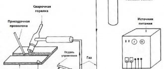
4.2. Self-tapping and self-drilling screws
Thread rolling or thread cutting screws are installed in a pre-drilled or punched hole, as well as in special grooves of extruded aluminum profiles. These screws can also be self-drilling, when they have a drill or a special point at their end (Figure 5).
Figure 5 - Self-tapping and self-drilling screws
See more: Self-tapping screws in construction
4.3. Blind rivets
When components need to be connected to each other, and there is no access to the rear side of the connection, the use of so-called “blind” rivets is often the solution. In domestic technical practice, one type of “blind” rivets is most often used, which are called blind rivets. To install these rivets, an appropriate tool is used - a “riveter”, which pulls out the rivet core, which with its thickened head forms the rear part of the rivet.
When installing a rivet, the riveter first presses the parts to be joined together with force, and then forms the rear head of the rivet. With a further increase in load, the tail of the core is torn off at a point specified by a special cut. Typically, the head of the core remains inside the body of the rivet and provides it with a certain seal (Figure 6).
Figure 6 - Blind rivet installation process
Blind rivets that are suitable for aluminum structures are made from austenitic stainless steel or aluminum-magnesium alloys. Typically, the rivet body and core are made from different aluminum alloys as they must perform different functions. The body of the rivet must be soft enough to form the head, while the core must be strong enough to be able to plastically deform the body of the rivet.
The shear stress of a blind rivet depends on the properties of the material in the shear plane. It is not possible to calculate this voltage. The fact is that the strength properties of the material of the rivet body and core, as well as their dimensions after plastic deformation during installation, differ from the properties of the material as delivered. Therefore, most often the strength of rivets is determined experimentally for each individual design solution.
Fastener materials
For the manufacture of fasteners, materials are used that have sufficient elastic properties to be able to elongate (stretch) under load and then return to their original shape after the load is removed.
The main materials for the manufacture of fasteners are various types of steel:
- low-carbon steels (“soft” steels);
- high-strength steels;
- stainless (corrosion-resistant) steels.
5.1. Low to medium strength bolts and screws
Manufactured from low carbon steels.
Increased strength due to:
— hardening during cold stamping.
5.2. High strength bolts
Manufactured from medium carbon steels. Ultimate strength is achieved through:
- hardening during cold stamping;
- thermal hardening.
5.3. Stainless steel fasteners
Austenitic stainless steels achieve varying levels of strength by:
- cold plastic processing.
Martensitic stainless steels achieve varying levels of strength by:
- cold plastic processing and
- thermal hardening.
5.4. Self-tapping/self-drilling screws
Manufactured from medium carbon steels. Strength properties are obtained due to:
- cold plastic processing;
- thermal hardening.
Strength classes of fasteners
6.1. Strength classes of bolts made of carbon and alloy steels:
4.6, 4.8, 5.6, 5.8, 6.8, 8.8, 10.9, 12.9
The strength class depends on the grade of steel and the method of manufacturing the bolts and is indicated by two numbers. The first number, multiplied by 100, means the value of the minimum tensile strength in MPa, the second, multiplied by 10, means the ratio of the yield strength to the tensile strength in percent.
Figure 8 — Marking of bolt strength class
6.2. Strength classes of nuts made of carbon and alloy steels:
4, 5, 6, 8, 10, 12
Here the number multiplied by 100 indicates the minimum tensile strength in MPa.
Figure 9 — Marking of nut strength class
6.3. Austenitic stainless steel bolts and nuts:
Bolts and nuts made of austenitic stainless steels have the same strength classes:
50, 70, 80
The number multiplied by 10 indicates the minimum tensile strength in MPa.
Figure 10 — Marking of bolts made of austenitic stainless steels
6.4. Washer hardness classes:
100 HV, 140 HV, 200 HV, 300 HV
6.5. Comparison of strength classes of bolts made of carbon and stainless steels
Figure 11 — Place of strength classes of stainless steels among the strength classes of carbon steels [3]
6.6. Combination of bolt and nut strength classes
Bolt strength
The required strength of connections when using high-strength bolts is achieved by friction that occurs between the surfaces of the fastened elements. To obtain a similar effect, as well as the necessary friction force, the bolts should be provided with increased tension.
Conventional bolts are unable to withstand such a load, so similar high-strength fasteners of classes 10.9 and 8.8 are used instead. It is usually made from steel grades 40X and 40HFA. Some other brands can also be used, but their resistance in any case should not be less than 800 MPa.