What is ultrasonic testing of welding joints
Ultrasonic testing of welded joints, which is often called flaw detection, is a non-destructive testing method, during which all internal mechanical defects present in the joint, as well as chemical deviations from current standards, are identified.
This technology diagnoses welded joints of various types. An effective technique is for detecting slag inclusions in metal, identifying air voids, the presence of non-metallic elements and chemically heterogeneous composition.
The essence of ultrasonic testing technology
Ultrasonic testing of welded joints is based on the emission of ultrasonic waves of the acoustic type, which, when passing through a homogeneous medium, do not change the straight trajectory.
The principle of the technology is based on the ability of high-frequency vibrations (above 20 kHz) to penetrate metal without disturbing its structure, and to be reflected from the surface of voids, scratches, irregularities or foreign inclusions. An artificially created wave penetrates inside the welding joint being tested and if there is a defect in it, then it deviates from its natural direction when it is detected.
All deviations are reflected on the screens of special devices. The signal to the monitor is transmitted using an amplifier. It helps to build a diagram according to which the operator can see all the defects and features of the butt joints. The size of the defect formation is determined by the amplitude of the reflected pulse, the distance to it is determined by the propagation time of the acoustic wave.
LECTURE 10 – Pulse echo testing method
One of the most common ultrasonic testing methods is the pulse echo method. This is explained by the fact that this method - unlike others - is applicable with one-sided access to the object under study, and at the same time allows one to determine the coordinates of the defect with high accuracy.
The echo method is based on emitting short pulses of elastic vibrations into the controlled product and recording the intensity (amplitude) and time of arrival of echo signals reflected from defects. The time interval between the probing pulse and the echo pulse is proportional to the depth of the defect, and the amplitude is proportional to the reflectivity of the defect.
The pulse echo method allows you to solve the following flaw detection problems : detection and determination of the coordinates of defects; determination of the size of defects and products; detection of coarse-grained zones in products and workpieces.
A distinctive feature of the echo method is that when testing products, almost all signals coming from the product after emitting probing oscillations are recorded and analyzed.
When testing materials and products using the echo method of ultrasonic flaw detection, interference . They are divided into several types:
– interference from the flaw detector amplifier. These interferences prevent an unlimited increase in the gain of the receiving path of the flaw detector and determine the limiting value of the signal recorded by the device. On the flaw detector screen at high magnification, an increase in thickness or blurring of the scan line is visible;
– noise of the converter that occurs when it operates according to a combined scheme (multiple reflections in the protector, the probe prism). Immediately after the radiation of the probing pulse, the sensitivity of the amplifier is sharply weakened due to the strong dynamic effect on it of the powerful signal of the probing pulse generator. As a result, pulses following the probing signal are visible in the zone closest to the probing signal. When the probe comes into contact with some product or a flaw detector's finger, the probe interference changes its amplitude, but maintains its position on the scan line. The amplitude of the interference is very high; the useful signal against the background of this interference can be distinguished by the fact that it moves along the scan line while the transducer is moving. These interferences are reduced by improving the design of the converter. For example, for RS probes this interference is minimal;
– false signals resulting from reflection from protrusions or recesses and other surface irregularities. These interferences interfere with the detection of defects in certain areas of the test object. The level of false signals is reduced by changing the control circuit, for example, by increasing the probe input angle. Interference from false signals is distinguished from useful signals by accurately measuring the coordinates of the reflector;
– interference associated with the scattering of ultrasound on structural inhomogeneities, grains of the material, i.e. interference due to structural reverberation. Signals from inhomogeneities weaken or strengthen each other depending on the phase. They are displayed on the screen in the form of a large number of pulses, randomly changing in amplitude and position on the scan line as the probe moves. Materials consisting of a large number of large grains that strongly reflect ultrasound give signals similar to signals from defects. Such materials are not subject to ultrasonic testing.
Thus, the advantages of the echo method include :
– one-way access to the product;
– relatively high sensitivity to internal defects;
– high accuracy in determining the coordinates of defects.
The disadvantages of the echo method include:
– low noise immunity to surface reflectors;
– sharp dependence of the amplitude of the echo signal on the orientation of the defect;
– the impossibility of monitoring the quality of acoustic contact during the movement of the probe, since in the absence of defects there are no signals at the output.
1 Features of the propagation of ultrasonic waves in a controlled object using the echo method
Since it was mentioned above that the echo method is very sensitive, when inspecting products it is possible not only to receive echo signals from defects, but also from the wall opposite to the ultrasound input, from structural reflectors, depressed marker marks, technological holes, etc.
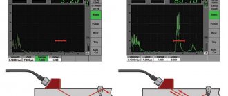
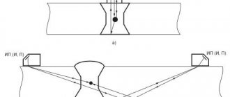
When inspecting products with plane-parallel surfaces using a direct probe switched on using the echo method, it is possible to simultaneously receive echo signals from both the defect and the surface opposite to the input (Figure 90). Moreover, the position on the scan line of echo signals from the reflectors relative to the probing pulse is proportional to the travel time of the pulse to a given reflector.
Figure 90 – Formation of echo and bottom signals
The signal from the opposite surface of the product when testing with a direct probe may be absent in the following situations:
– the bottom surface is not parallel to the ultrasonic testing input surface (Figure 91, a
);
– the defect has a significant size, completely covering the ultrasound beam in a given section (Figure 91, b
);
a) b)
Figure 91 – Features of the propagation of ultrasonic waves in the controlled product when working with a direct probe in the echo method
– the height (thickness) of the product is so great that, due to the attenuation of ultrasonic vibrations, the amplitude of the echo signal from the opposite surface is very small (Figure 92, a
).
Attenuation in this case depends on the dispersion of ultrasonic signals on the grains of the metal structure, as well as on the divergence of the beam of rays with distance from the excitation point. In order for the dispersion of ultrasonic testing on grains not to distort the flaw detection results, it is practically necessary to have λ˃(10...100 D
).
If this condition is met at the upper limit (λ≥100 D
), then it is usually possible to control the metal to a depth of 8–10 m or even more. The attenuation of the USV due to the divergence of the beam of rays is compensated by introducing additional gain in the far zone by adjusting the time-lapse frequency control, which increases the overall gain in this zone by a certain amount;
– when testing products of small thickness with a direct probe, it is possible to obtain a whole series of echo signals repeatedly reflected from the plane-parallel walls of the product (Figure 92, b
). Due to the attenuation of ultrasonic vibrations, multiple reflections successively decrease in amplitude. The distance between individual reflections is a constant value, depending on the thickness of the product. This property is used when adjusting the accuracy of the depth gauge of a flaw detector with a direct transducer.
a) b)
Figure 92 – Features of the propagation of ultrasonic waves in the controlled product when working with a direct probe in the echo method
When testing with an inclined probe, there is almost never a reflection from the surface opposite to the input surface of the object, since this surface is usually mirror-like (Figure 93, a
).
According to the laws of geometric optics, which are valid for smooth surfaces, the re-reflection of the ultrasound wave from this surface occurs with a change in the direction of propagation of the ultrasound wave. Such a wave does not return to the finder. When ultrasonic waves are reflected from rough surfaces, diffuse reflection occurs, accompanied by the dissipation of part of the energy in different directions. Naturally, in this case, part of the USV energy is returned to the finder, which means that a pulse appears on the scan line, the temporary position of which relative to the probing pulse is proportional to the distance to the reflecting surface (Figure 93, b
). Based on these examples, we can conclude that when monitoring using the echo method (especially with an inclined finder), tracking the acoustic contact is difficult.
| b) |
A)
Figure 93 – Features of the propagation of USV in the OC when working with an inclined probe in the echo method
Properties and production of ultrasonic vibrations
Almost all devices used for ultrasonic flaw detection of welds are designed according to a similar principle. A plate consisting of barium titanium or quartz is the main working element of the device. The piezoelectric sensor of the device is located in the prismatic head, which is responsible for searching for defects.
The head (probe) is placed along the connections and moves slowly through a reciprocating motion. A high-frequency current in the range of 0.8-2.5 MHz is supplied to the plate and, as a result, it begins to emit waves perpendicular to its length.
The outgoing waves are picked up by another receiving plate, where they are converted into electrical alternating current, which instantly rejects the wave on the oscilloscope monitor.
The sensor sends alternating oscillation pulses of different durations, dividing them into pauses with a longer duration from 1 to 5 μs. This process makes it possible to accurately carry out ultrasonic inspection of welds, determine the presence of defects, their type and depth.
Types of ultrasonic flaw detection
The ultrasonic method of testing welded joints is regulated by GOST 23829-79 and is carried out in several ways:
- shadowy _ The test is carried out using two devices, which are installed on opposite sides of the test area along a perpendicular plane. The first emits waves, the second receives them. If a blind zone appears when receiving reflections, this indicates the presence of a defect in this place;
- pulse echo. This method uses one ultrasonic flaw detector to control welded joints, the parameters of which determine the direction and reception of radiating pulses. Reflection occurs through its reflection from damaged areas. If the waves pass straight and without obstacles, then such a section of the welding joint is considered to be of high quality. When reflection occurs and the wave returns to the device, this section is designated as defective;
- echo-mirror . The control principle is almost the same as in the previous method. The difference is the presence of a reflector, which is installed at a right angle. Waves are sent to the connecting seam and reflected to the receiver if there are defects on it. This type of ultrasonic inspection of welds is usually used to detect vertical defects and cracks;
- mirror-shadow . The test is carried out by two devices installed on one side of the controlled area. The waves are oblique and reflected from the mesh of the base metal. With non-standard impulses, the place is considered damaged;
- delta method . Diagnostics of welds consists of re-radiation from the defect directed into the joint. This method is rarely used, since it is characterized by a rather lengthy decoding of the results, and also requires specific configuration of the equipment.
In most cases, ultrasonic quality control of welded joints is carried out by pulse-echo and shadow methods based on the reflection of an acoustic wave from a defect.
The essence of the ultrasonic method
The principle of ultrasonic flaw detection was first proposed in 1928: Soviet scientist Sergei Sokolov showed how to detect damage to metal and other materials through variations in ultrasonic energy. Sokolov invented the first flaw detector, in which he used ultrasonic vibrations to determine internal defects, cracks, foreign inclusions and the structure of materials. Subsequently, this experience was picked up by scientists from other countries, and the method spread, becoming mandatory for many industries.
The ultrasonic method of metal testing is based on the physical law of the invariability of the trajectory of sound waves, provided the medium is homogeneous. The essence is to identify damage to the material through the radiation and acceptance of ultrasonic vibrations when reflected from a defect, analyzing the amplitude of vibrations, return time, shape and other parameters.
For analysis, high-frequency oscillations (over 20 kHz) are created in the material using a flaw detector and transducers with a piezoelectric element. If there are no flaws, the vibrations do not encounter obstacles and are not reflected. If there are inhomogeneities (for example, cracks, voids or other inclusions), the receiver will register reflection signals from them.
The wave propagation time indicates the depth of the defect, and the pulse reflection amplitude indicates the size of the inhomogeneity.
Procedure for carrying out ultrasonic testing
There is a certain standard according to which ultrasonic testing of welded joints of pipelines or other metal structures must be carried out. The procedure for performing control operations is as follows:
- thorough cleaning of butt joints from rust and paint coatings of at least 50-70 mm on both sides of the seam;
- the surface of the joint and the metal near it is treated with machine, turbine, transformer oil, glycerin or grease. Such processing is necessary to obtain more accurate verification results;
- The testing device is configured in accordance with the parameters characteristic of a specific type of ultrasonic testing. When the thickness of the material under study is up to 2 cm, standard settings are used; DGS diagrams are adjusted if the thickness exceeds 2 cm. DGS or AVG diagrams are used to check quality;
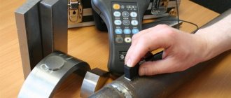
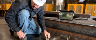
- the emitter of the device moves in a zigzag motion along the welding seam, turning 10-15 around its own axis;
- The finder moves through the material until a stable, clearest signal appears. After this, the device turns around and searches for the highest amplitude signal.
Wave reflection fluctuations are often perceived as defects, so this point must be carefully checked. If damage actually occurs, it is recorded and the location is indicated.
Ultrasonic testing of welds must be carried out in accordance with the requirements established by GOST. If it is not possible to accurately determine the nature of the defect using ultrasonic testing, then in such cases more detailed checks are carried out using gamma flaw detection or X-ray flaw detection.
Scope of application of the ultrasonic testing method
Ultrasonic testing of welded joints provides fairly accurate results and, if the technology is followed, can provide comprehensive information regarding any defects. But here it should be understood that there are certain limits to the application of the technique.
The defects that can be detected by ultrasonic testing are the following:
- pores;
- uncooked areas;
- cracks in and around seams;
- failure of joints;
- delamination of deposited material;
- presence of fistulas;
- sagging of the metal in the lower areas of the joint;
- corrosion formations;
- areas where the geometric dimensions are violated or there is a discrepancy in the chemical composition.
Ultrasonic testing of welded joints can be carried out on structures made of alloy and austenitic steel, copper, cast iron and metals that do not conduct ultrasound well.
Geometric parameters of ultrasonic flaw detection:
- no more than 10 meters is the greatest depth of the seam;
- with a minimum metal thickness of 3-4 mm;
- depending on the device, the minimum thickness of the seam should be in the range of 8-10 mm;
- 500-800 mm - maximum metal thickness.
As for the types of joints, ultrasonic welding involves making longitudinal, flat, welded, ring, and T-joints. The technique is also used for welded pipes.
Areas of use of flaw detection
Ultrasonic inspection of welds is actively used in industrial, construction and other fields. Ultrasound testing is most often used:
- for analytical diagnostics of units and components;
- flaw detection of pipeline welds is carried out to determine their integrity and the degree of pipe wear;
- in nuclear and thermal energy to monitor the condition of welded structures;
- in the field of mechanical engineering and chemical industry;
- for checking welded joints in products with complex configurations;
- if necessary, check the strength of metal joints with a coarse-grained structure.
Ultrasonic testing can be used both in laboratory and field conditions when joints are located at heights, in confined spaces and hard-to-reach places.
Advantages and disadvantages of the technique
Ultrasonic testing of pipeline welds or other types of metal products has a number of advantageous features:
- high sensitivity of the equipment ensures the accuracy of results and speed of inspections;
- ease of use due to the compactness of the devices;
- the possibility of carrying out on-site flaw detection if portable measuring devices are used for control;
- minimal costs for monitoring welds, which is due to the low cost of the flaw detectors themselves;
- ability to check connections with large thickness;
- Ultrasonic testing does not disrupt the structure of the seam and does not damage the object being examined;
- almost all types of weld defects can be identified using ultrasonic testing;
- the controlled object does not need to be taken out of service; welding connections can be checked directly during its operation;
- absolute safety for humans, which cannot be attributed, for example, to x-ray flaw detection.
The disadvantages of testing welds using the ultrasonic method include some difficulties when testing metals with a coarse-grained structure, which arise due to strong attenuation and scattering of waves. Also among the disadvantages are the need to first clean and prepare the surface of the seam before installing flaw detectors and some limited information provided by the device about the detected defect.
In conclusion, it should be said that ultrasonic testing of welding joints is a guarantee of the safe operation of finished metal products and structures. If you comply with the inspection deadlines, this will allow you to eliminate damage in a timely manner, extend the periods and increase the efficiency of the structures.
Necessary equipment for flaw detection
For ultrasonic diagnostics, a flaw detector, a transducer with a built-in piezoelectric element (designed to emit and/or receive ultrasonic vibrations) and additional devices are used.
There are 3 types of ultrasonic transducers:
- Direct: emission of longitudinal waves at right angles to the surface being tested. They may have a ceramic piezoelectric element (made of barium titanate or lead zirconate titanate). Models from foreign brands use quartz - it has a relatively low sensitivity, which ensures uniform radiation and stable operation.
- Oblique (or prismatic): radiation of transverse waves into metal at an angle to the input surface. They carry out vertical scanning of parts and are used in cases where it is not possible to install the transducer directly on the surface of the material (for example, in corner joints, in structures with a complex profile).
- Separate-combined: the entry of longitudinal waves into the metal at an angle of 80-85º to the input surface. They have 2 piezo valves, one of which is a generator, and the second is a receiver. Suitable for working with rough materials and deformed surfaces.
A flaw detector is a device for detecting cracks in products.
The main component of the converter is a piezoelectric element in the form of a rectangular plate or disk. The thickness of the piezoelectric element is half the length of the emitted waves. In direct and inclined transducers, the piezoelectric element acts as an emitter and receiver of ultrasonic vibrations at the same time.
Diagram of the flaw detector
A flaw detector is an electronic unit for converting and amplifying echo signals when reflected from a defect, creating high-voltage probing pulses and visually displaying the amplitude-time characteristics of echo signals.
We recommend reading: Types of welding stations and information about them
A built-in switch is provided for directly connecting the amplifier to the radio pulse generator or disconnecting it from it (depending on the operating scheme). An automatic alarm detects a defect with a sound or light signal.
Flaw detector diagram.
The device may have additional blocks that expand the functions of the device and simplify the operator’s work. These include a temporary sensitivity control unit, which creates the same signal amplitude when detecting deformations of different sizes. This improves measurement accuracy.
Approximate cost of a flaw detector and other tools
The price range for flaw detectors is wide - from 90,000 to 2,500,000 rubles. The cost depends on the performance characteristics, brand and country of manufacture, year of manufacture. The price of stationary (for research in laboratories) and portable (for field conditions) models varies. The ability to connect to a PC, the amount of built-in memory and compatibility with several types of converters also affect the final cost. When choosing, you should start from the planned tasks and the expected scope of application.