One of the most common causes of electronic equipment malfunction is the breakdown of one or more capacitors that form an integral part of its board. And in order to find out which capacitor turned out to be the weak link, it is necessary to check their performance. This article describes how a capacitor is called. Regardless of whether you work with electronic equipment professionally or you are just a hobbyist, you can do it. For this you will need a multimeter. Below we will look at how to test a capacitor with a multimeter yourself.
Types of capacitors and their testing
Before we figure out how to test a capacitor with a multimeter, let's find out what types of capacitors exist. All capacitors are divided into polar and non-polar. The difference between them is that polar, as the name suggests, have polarity. They need to be checked strictly accordingly: “plus” to “plus”, “minus” to “minus”, since otherwise they will become unusable and may explode. All polar capacitors are electrolytic. If the capacitor is still Soviet-made, then in the event of an explosion the electrolyte may get on your skin. In modern capacitors for such cases, a special section is provided on the surface, which breaks in a certain direction and prevents the conductive substance from splashing in different directions.
How to check depends on the nature of the breakdown, since you can use a multimeter to check the functionality of a capacitor in two ways: by measuring the resistance of its dielectric and by measuring its capacitance.
Method number 2 – Let’s do without instruments
A less qualitative way to check the functionality of a capacitive element is using a homemade dialer in the form of a light bulb and two wires. In this way you can only check the capacitor for a short circuit. As in the case of a screwdriver, we first charge the part, after which we touch the legs with the probe leads. If the condenser is working, a spark will occur, which will instantly discharge it. We also talked about how to make an electrician's warning lamp.
Capacitor breakdown
The most common problem with capacitors is dielectric breakdown. A dielectric is a layer of material between two conductors inside a capacitor that has a high resistance to prevent current from flowing between the conductors.
In a working capacitor, a small amount of current is allowed to pass through this insulator, this is called “leakage current”, and it is negligible. When a dielectric breaks down, its resistance drops sharply, and, in fact, it turns into an ordinary conductor. The cause of such a breakdown, as a rule, is a sharp drop in voltage in the network to which the equipment is connected. Characteristic signs of a breakdown include swelling of the capacitor body, its darkening and the appearance of black spots. Before checking the capacitor for serviceability, inspect it visually for external defects.
What to do in case of breakdown
The most common problem that occurs with capacitors is the appearance of breakdown on the dielectric. Dielectrics are a kind of layer of insulating material with high resistance, located between one and the second conductor, preventing the flow of current between them.
In serviceable elements, a small amount of current can leak through the insulating coating, referred to as “leakage current.” If a breakdown occurs in the dielectric, then a sharp decrease in resistance occurs, and it becomes an ordinary conductor. A breakdown can occur as a result of a sudden voltage drop in the electrical network from which the equipment operates. A characteristic sign of a breakdown: a swollen device body, a darkened surface and black spots on it. Before checking the capacitors with a multimeter for serviceability, it is worth inspecting it visually to determine possible external defects.
Checking a non-polar capacitor in ohmmeter mode
Using a multimeter to check the dielectric resistance in a capacitor is carried out in ohmmeter mode. In non-polar capacitors, the dielectric can be made of glass, ceramics, paper, or even in the form of an air gap. This ensures extremely high resistance, and in a working capacitor the digital multimeter will show a virtually infinite value. If an electrical breakdown occurs, then the resistance level will be within a few ohms, a maximum of several tens.
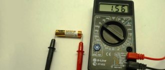
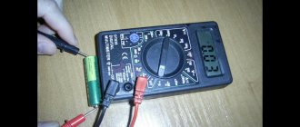
Before ringing the capacitor with a multimeter, turn on the appropriate mode on the measuring device, setting it to the highest possible resistance measurement level. Apply the multimeter probe to the terminals of the capacitors and look at the display: if the capacitor is in order, then a 1 should appear there, which indicates that the resistance is higher than the set maximum. If the multimeter display shows a specific value that is less than the measuring maximum, then this may indicate a malfunction of the capacitor being tested.
Remember safety precautions and do not hold both the probes of the device and the capacitor terminals at the same time, since due to the lower resistance, the electric current will flow through your body.
Types of transistors
Standard modern transistors differ in structure, principle of operation and basic parameters according to which they can be presented:
- Bipolar devices , which are distinguished by the presence of three layers in the form of a “base”, “collector” and “emitter”. The semiconductor material is responsible for the flow of current exclusively in one direction, determined by the type of transition. A characteristic feature of this type of transistor is the supply of negligible currents to the base.
- Field or unipolar devices , which are distinguished by the presence of three terminals in the form of “gate”, “drain” and “source”. The resistance values of the conductor zone directly depend on the voltage level applied to the gate part. In accordance with the conductivity of the crystal, devices with a p-channel and an n-channel are produced.
Electrical or electronic components represented by a capacitor, unlike transistors, include a pair of conductor plates separated by a dielectric layer.
There are a huge number of varieties of capacitor devices, which most often differ in the material of the plates and the type of dielectric:
- paper and metal-paper type;
- electrolytic varieties;
- polymer or film type;
- ceramic type;
- with the presence of an air-type dielectric.
Types of transistors
Among other things, capacitor devices can be polar or non-polar. The second option is used to ensure periodic, short-term inclusion in a circuit with variable current indicators. Polar electrolytic capacitors are significantly smaller in size than non-polar devices with the same capacitance.
If all transistors are responsible for the flow of current in accordance with the control signal, then capacitors accumulate and then release electric current, therefore they are often used to equalize voltage surges.
Checking a polar capacitor in ohmmeter mode
Compared to non-polar capacitors, the dielectric resistance in polar capacitors is an order of magnitude lower, so the maximum resistance on the multimeter must be set accordingly. Most of these capacitors have a resistance of at least 100 kOhm, especially powerful ones up to 1 mOhm. Before ringing the capacitor with a multimeter, short-circuit the terminals of the drive to completely discharge it.
Having set the appropriate measurement limit, connect the probes of the device to the capacitor, observing the polarity. Electrolytic capacitors have a relatively large capacitance, and therefore, when connected, they immediately begin to charge. While charging is in progress, the resistance will increase in direct proportion, which will be displayed on the device screen. The capacitor can be considered serviceable in most cases when the resistance exceeds the 100 kOhm mark.
How to find out the capacitance of a capacitor
In most cases, the capacity of the device is indicated in the markings on the element body. However, there is often a need to determine the capacity of electronic components with insufficiently clearly labeled data.
Most multimeters have 5 measurement limits:
- 20 nF (20nF)
- 200 nF (200nF)
- 2 µF (2uF)
- 20 µF (20uF)
- 200 µF (200uF)
This range of measuring the capacitance of elements allows testing both non-polar capacitors and polar, that is, electrolytic. The testing process itself looks like this:
- The control probes of the device are switched to special capacitance measurement sockets (Cx sockets).
The resulting value shows the capacity of the electronic component of the circuit.
In some multimeters, instead of special sockets, metal plates are placed on the working panel. The element is checked by connecting the leads to the platinums while maintaining polarity.
How to test a capacitor with a multimeter (analog meter)
The same procedure can be done using an analog (dial) meter. The capacity of an electrolytic capacitor can be determined by the speed of movement of the instrument needle towards the maximum. The slower the needle moves, the longer it takes to charge the capacitor and, accordingly, the greater its capacity. If the capacitance is between 1 and 100 microfarads (µF), the needle will reach the right edge of the dial almost instantly. With a capacitance of 1000 µF or more, its path may take several seconds.
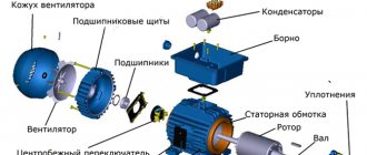
How to check the motor winding on the stator: general recommendations
The three-phase stator has three built-in windings. There are six wires coming out of it. In some designs you can find 3 or 4 terminals, when the triangle or star connection is assembled inside the housing. But this is rarely done.
Testing them with a multimeter in ohmmeter mode allows you to determine whether the ends are connected to the windings. You just need to place one probe on an arbitrary pin, and use the other one to alternately measure the active resistance on all the others.
The pair of wires on which resistance in Ohms is detected will belong to the same winding. They should be visually separated and marked, for example, with the number 1. Do the same with other wires.
Here we must clearly understand that, according to Ohm’s law, the current in the winding is created under the influence of the applied voltage, which is counteracted by the total resistance, and not by the active one measured by us.
We take into account that the windings are wound from the same wire with the same number of turns, creating equal inductive reactance. If the wire is short-circuited or torn during operation, its active component, as well as its full value, will be disrupted.
The interturn short circuit also affects the value of the active component.
Single-phase asynchronous motor: features of stator windings
Such models are created with two windings: working and starting, like, for example, a washing machine. In the vast majority of cases, the active resistance of the working chain is always less.
Therefore, when only three ends are removed from the stator, this means that the resistance must be measured between all of them. The results of three measurements will show:
- the smaller value is the working winding;
- middle - starting;
- large - serial connection of the first two.
How to find the beginning and end of each winding
The method only allows you to identify the general winding direction of each wire. But for practical operation of the electric motor this is more than enough.
The stator is considered as an ordinary transformer, which in principle is what it actually is: the same processes occur in it.
To operate, you will need a small constant voltage source (a regular battery) and a sensitive voltmeter. Better than a pointer. It displays information more clearly. It is difficult to monitor the change in sign of a rapidly changing pulse on a digital multimeter.
A voltmeter is connected to one winding, and voltage from the battery is briefly applied to the other winding and immediately removed. The deviation of the arrow is assessed.
If, when applying a “plus” to the first winding, an electromagnetic pulse was transformed into the second, deflecting the arrow to the right, and when it is turned off, it moves to the left, then it is concluded that the wires have the same direction when the “+” of the device and the source coincide.
Otherwise, you need to switch the voltmeter or battery - that is, change the ends of one of the windings. The next third chain is checked in the same way.
And then I simply took my working asynchronous engine with a multimeter and showed with photographs the method for evaluating it.
Personal experience: checking the stator windings of an asynchronous electric motor
For this article I used my new Mestek MT102 pocket multimeter. At the same time, I continue to identify the shortcomings of its design, which I already showed in the article earlier.
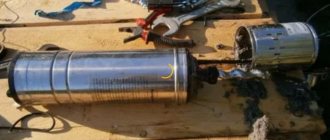
Electrical tests were carried out on a three-phase motor connected to a single-phase network through capacitors in a star configuration.
General assessment of the winding insulation condition
Since all the windings are already assembled together at the terminal terminals, I started taking measurements by checking their insulation resistance relative to the housing. One probe is located on the terminal block of the zero assembly, and the second is on the socket of the cover fastening screw. My Mestek showed no leaks.
I didn't expect any other result. This method of measuring the insulation condition is very inaccurate and it simply cannot detect most damage: 3 volt battery power is clearly not enough.
But it’s still better to do at least this way than to completely neglect such a check.
To fully analyze the dielectric layer of conductors, it is necessary to use the high voltage that megohmmeters produce. Its value usually starts from 500 volts and above. The home master does not have such devices.
You can do it indirectly, using a household network. To do this, a voltage of 220 volts is supplied to the winding and housing terminals through an incandescent test lamp with a power of about 75 watts (a current-limiting resistance that excludes the supply of phase potential to the circuit) and a series-connected ammeter.
Read also: Three-phase asynchronous motor in a single-phase network
The expected leakage current through normal insulation will not exceed microamps or their fractions, but you need to count on emergency mode and start measuring within amperes. By measuring the current and voltage, the insulation resistance is calculated.
When using this method, keep in mind that:
- a full-fledged phase is supplied to the motor body: it must be located on a dielectric base and have no contact with other objects;
- even a temporarily assembled circuit requires reliable insulation of all ends and wires, strong fastening of all clamps;
- The lamp bulb may break: it must be kept in a protective case.
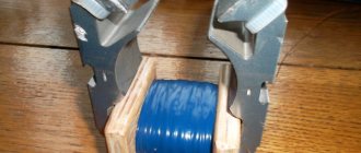
Measurement of winding resistance
Here you need to disassemble the wiring diagram and remove all jumpers. I switch the multimeter to ohmmeter mode and determine the active resistance of each winding.
The device showed 80, 92 and 88 Ohms. In principle, there is no big difference, and I explain deviations of several ohms by the fact that the crocodile does not provide high-quality electrical contact. Different transition resistance is created.
This is one of the disadvantages of this multimeter. The probe does not fit well into the crocodile groove, and besides, the thin metal of the clamp moves apart. I immediately had to tighten it with pliers.
Measuring insulation resistance between windings
I show this principle because it must be followed between each winding. However, instead of an ohmmeter, you need a megohmmeter or, as a last resort, check with household voltage according to the method I described above.
A multimeter can be misleading: it will show good insulation where hidden defects will be created.
How to test a capacitor with a multimeter: instructions for checking storage capacity
Although capacitors are often tested with an ohmmeter, a more reliable way to determine its health is to measure the capacitance.
Increased leakage (including due to breakdown) in the electrolytic capacitor leads to a partial loss of capacity, and its actual value no longer corresponds to that declared on the drive case. By measuring the resistance of a capacitor, it is very difficult to determine this defect; this requires a capacitance meter. Keep in mind that not all multimeters have this feature, so make sure your device is capable of performing this measurement. Before checking an electrolytic capacitor in this way, it must be completely discharged. A charged capacitor can simply ruin your multimeter. This is especially true for polar drives with high operating voltage and large capacity. As a rule, such capacitors are used in pulse units as filtering accumulators.
How to test a film capacitor with a multimeter
The main malfunctions of film devices can be presented:
- decrease in nominal capacity indicators during the drying process;
- exceeding specified leakage current values;
- increased active losses within the circuit;
- the appearance of a short circuit on the plates;
- loss of contact or breakage.
Film devices made for different voltage limits can be used not only in circuits with constant current values, but also inside filters or standard resonant circuits.
Capacity and performance of the capacitor
Checking the device for serviceability is carried out with a multimeter set to capacitance testing mode. In arrow models of testers, the level of arrow deviation or “jump” is monitored with a return to “0”.
In this case, we can assume the presence of a breakdown, which is often the main cause of a short circuit in the circuit. If the needle deflects quite slightly and does not reach the “∞” indicator, a current leak is diagnosed due to insufficient element capacity.
The ineffective operation of a device with a low power level during current leakage does not allow the device to realize its potential at 100%, therefore the use of such a model of a capacitor element is inappropriate.
Capacitor discharge
To discharge low-voltage capacitors, it is enough to simply short-circuit their terminals, but in the case of high-voltage and large capacitance capacitors, a 5-10 kilo-ohm resistor should be connected to the terminals. A resistor is needed to prevent a spark from occurring during a short circuit. Remember to be safe and never touch the capacitor terminals, otherwise a short circuit will occur to you.
How to discharge a capacitor in a microwave
You can discharge it in the following ways:
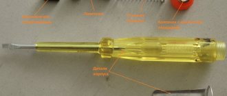
Having disconnected from the power supply, the capacitor is discharged by carefully closing its terminals with a screwdriver. A good discharge indicates its good condition. This method of discharge is the most common, although some consider it dangerous and can cause harm and destroy the device.
Discharging a capacitor with screwdrivers
The high voltage capacitor has an integrated resistor. It works to discharge the part. The device is located under high voltage (2 kV), and therefore there is a need to discharge it mainly to the housing. It is better to discharge parts with a capacity of more than 100 uF and a voltage of 63V through a resistor of 5-20 kiloOhms and 1 - 2 W. For this purpose, the ends of the resistor are combined with the terminals of the device for a certain number of seconds to remove the charge. This is necessary to prevent the occurrence of a strong spark. Therefore, you need to worry about personal safety.
Capacitor break
A break is a fairly rare malfunction for capacitors. As a rule, it occurs due to mechanical damage to the drive. As a result of a break, the capacitor completely loses its storage function and has zero capacity. In fact, it turns into two conductors isolated from each other. It is almost impossible to detect a break using an ohmmeter. A peculiar symptom of a break in polar electrolytic capacitors when measuring resistance is the absence of any change in the readings of the device. Since a serviceable low-capacity non-polar capacitor has a high resistance, it is therefore not possible to check it for an open circuit. The only way out is to measure the capacitance.
Checking for internal continuity
A break is a common defect in a capacitor in which one of its electrodes loses electrical connection to the plate and actually turns into a short conductor not connected to anything (hanging in the air).
Most often, a break occurs due to the operating voltage of the capacitor being exceeded. This is caused not only by electrolytic capacitors, but also by special noise-suppressing capacitors of the Y type (they, by the way, are specially designed to go into isolation and not into a short circuit).
A capacitor with an internal break is no different in appearance from a working one, except in cases where the leg is physically torn off from the body 
Of course, if one of the leads is torn off from the capacitor plate, the capacitance of such a capacitor becomes zero. Therefore, the essence of checking for a break is to catch at least the slightest sign of the presence of capacitance in the capacitor being tested.
How to do it? There are three ways.
Method No. 1: eliminating a break through the sound signal in dialing mode
Turn the multimeter into dial mode, touch the leads of the capacitor with the probes, and at this moment the multimeter should emit a short squeak. Sometimes the sound is so short (depending on the capacitor capacity) that it sounds more like a click and you have to try really hard to hear it.
A small life hack: to increase the duration of the sound signal when testing very small capacitors, you need to first charge them with negative voltage by applying the multimeter probes in the reverse order. Then, during the subsequent continuity test, the multimeter will first have to recharge the capacitor from some negative voltage to zero, and only then from zero until the tweeter turns off. All this will take much more time, which means the signal will sound longer and will be easier to hear.
Here's some dude, without even knowing it, using this life hack on video:
From my practice, I can say that using the trick described above, I was able to catch the response of a multimeter to a capacitor with a capacity of only 0.1 μF (or 100 nF)!
Method No. 2: increasing DC resistance as a sign of no break
If the previous method did not help and it is not at all clear how to check the capacitor with a tester, then here is a more sensitive testing method.
It is necessary to switch the multimeter to resistance measurement mode. Select the maximum available measurement limit (20 or better 200 MOhm). Apply the probes to the capacitor terminals and observe the multimeter readings.
As the capacitor is charged from the multimeter's internal source, its resistance will continually increase until it exceeds the measurement range. If such an effect is observed, then there is no break.
By the way, it may turn out that the increase in resistance will stop at a value from a few to a couple of tens of MOhms - for capacitors with liquid electrolyte (except tantalum) this is absolutely normal. For other capacitors, the leakage resistance should be at least an order of magnitude greater.
When measuring such high resistances, you must be careful not to touch both test leads with your fingers. Otherwise, skin resistance will make its own adjustments and distort all results.
By measuring resistance at a limit of 200 MΩ, I was able to unambiguously determine the absence of a break in capacitors with a capacity of only 0.001 μF (or 1000 pF).
Here's a video for clarity:
Method No. 3: measuring residual voltage to eliminate internal breakage
This is the most sensitive way to ensure that the capacitor is not broken even when all previous methods have failed.
Take a multimeter in continuity mode or in resistance measurement mode (no matter in what range) and apply the probes to the terminals of the capacitor under test for a couple of seconds. At this moment, the capacitor will be charged from the multimeter to some small voltage (usually 2.8 V).
Then we quickly switch the multimeter to DC voltage measurement mode on the most sensitive range and, without waiting too long, we again apply the probes to the capacitor to measure the voltage across it. If the capacitor has at least some intelligible capacitance, then the multimeter will have time to show the voltage to which the capacitor was charged.
Using this method, I was able to detect capacitance up to 470 pF (0.00047 µF) using a regular M890D digital multimeter! And this is a very small capacity.
Generally speaking, this is the most effective method for testing capacitors. In this way, you can check condensers of any capacity - from the smallest to the largest, as well as any type - polar, non-polar, electrolytic, film, ceramic, oxide, air, metal-paper, etc.
True, if the capacitor has a very small capacitance, up to 470 pF, then, alas, it will not be possible to check it for a break without a special device, like the previously mentioned LC meter.
Loss of capacitor capacity
In order to determine whether a capacitor has lost its capacity, oddly enough, you need to measure this same capacity. Set the multimeter to the appropriate capacitance limit, discharge the capacitor being tested, connect the meter probes to the corresponding sockets on it, observing the correct polarity, and finally touch the capacitor leads with the probes. Obviously, figuring out how to use a multimeter to check the capacitor of an air conditioner or any other household appliance for loss of capacity is not so difficult.
Checking and replacing the starting capacitor
What is a starting capacitor used for?
Starting and running capacitors are used to start and operate electric motors operating in a single-phase 220 V network.
That's why they are also called phase shifters.
Installation location: between the power line and the starting winding of the electric motor.
Symbol for capacitors in diagrams
The graphic designation on the diagram is shown in the figure, the letter designation is C and the serial number according to the diagram.
Basic parameters of capacitors
The capacitance of a capacitor characterizes the energy that the capacitor is capable of accumulating, as well as the current that it is capable of passing through itself. Measured in Farads with a multiplying prefix (nano, micro, etc.).
The most commonly used values for run and start capacitors range from 1 μF to 100 μF.
The rated voltage of a capacitor is the voltage at which the capacitor is able to operate reliably and for a long time, maintaining its parameters.
Well-known capacitor manufacturers indicate on its body the voltage and the corresponding guaranteed operating time in hours, for example:
- 400 V - 10,000 hours
- 450 V - 5000 hours
- 500 V - 1000 hours
Checking the starting and running capacitors
You can check the capacitor using a capacitor capacitance meter; such devices are produced both separately and as part of a multimeter, a universal device that can measure many parameters. Let's consider checking with a multimeter.
- de-energize the air conditioner
- discharge the capacitor by short-circuiting its terminals
- remove one of the terminals (any)
- We set the device to measure the capacitance of capacitors
- We lean the probes against the terminals of the capacitor
- read the capacity value from the screen
All devices have different designations for the capacitor measurement mode; the main types are shown below in the pictures.
In this multimeter, the mode is selected by a switch; it must be set to Fcx mode. The probes must be inserted into the sockets marked Cx.
Switching the capacitance measurement limit is manual. Maximum value 100 µF.
This measuring device has an automatic mode, you just need to select it, as shown in the picture.
The Mastech measuring tweezers also automatically measure capacitance, you just need to select the mode with the FUNC button, pressing it until the F indication appears.
To check the capacitance, we read its value on the capacitor body and set a deliberately larger measurement limit on the device. (If it's not automatic)
For example, the nominal value is 2.5 μF (μF), on the device we set 20 μF (μF).
After connecting the probes to the terminals of the capacitor, we wait for the readings on the screen, for example, the time to measure a capacitance of 40 μF with the first device is less than one second, with the second one more than one minute, so you should wait.
If the rating does not correspond to that indicated on the capacitor body, then it must be replaced and, if necessary, an analogue must be selected.
Replacement and selection of starting/running capacitor
If you have an original capacitor, then it is clear that you simply need to put it in place of the old one and that’s it. Polarity does not matter, that is, the terminals of the capacitor do not have the designations plus “+” and minus “-” and they can be connected in any way.
It is strictly forbidden to use electrolytic capacitors (you can recognize them by their smaller sizes, with the same capacity, and the plus and minus markings on the case). As a consequence of use - thermal destruction. For these purposes, manufacturers specially produce non-polar capacitors for operation in an alternating current circuit, which have convenient mounting and flat terminals for quick installation.
If the required value is not available, then it can be obtained by connecting capacitors in parallel . The total capacitance will be equal to the sum of the two capacitors:
Commun=C1+C2+…Sp
That is, if we connect two 35 μF capacitors, we get a total capacity of 70 μF, the voltage at which they can operate will correspond to their rated voltage.
Such a replacement is absolutely equivalent to one capacitor of larger capacity.
If the wires are mixed up during replacement, you can see the correct connection using the diagram on the case or here: Connection diagram for the capacitor to the compressor
Types of capacitors
To start powerful compressor engines, oil-filled non-polar capacitors are used.
The housing is filled with oil inside for good heat transfer to the surface of the housing. The body is usually metal or aluminum.
The most affordable capacitors of this type are CBB65 .
To start less powerful loads, such as fan motors, dry capacitors are used, the housing of which is usually plastic.
The most common capacitors of this type are CBB60 , CBB61 .
The terminals are double or quadruple for ease of connection.
Capacitor voltage measurement
Also, to ensure that the capacitor is working properly, you should check whether its actual voltage matches the rated voltage.
To do this, you will need the voltmeter mode on your multimeter and a power source to charge the capacitor. It should produce a voltage less than that for which the drive is designed. Connect the probes to the terminals and wait a bit until the capacitor is fully charged. Switching the device to voltmeter mode, check the voltage output by the drive. The value that appears on the multimeter screen immediately at the beginning of testing must correspond to the declared value. Please note that when checking, the drive loses its charge and the voltage will drop quickly, so it is important to see the number that appeared at the very beginning. There is a simpler way to check, but it is only effective for capacitors with a sufficiently large capacitance. Having fully charged the drive, take an ordinary screwdriver with an insulated handle, bring its metal part to its terminals and short-circuit them. If the result is a bright spark, it means the element is working. If the spark is very weak or absent altogether, it means that the capacitor does not hold a charge.
Tips and tricks
When starting to check elements, it is necessary to clearly understand that even the most modern multimeters are not capable of measuring the very large capacitance of such devices; in most cases, the maximum limit is the measurement of both polar and non-polar elements with a capacity of up to 200 µF (200uF).
It’s also a good idea for radio amateurs to remember about safety precautions when checking such high-voltage circuits.
Repair of household radio equipment that uses high-voltage circuits should begin after turning off the device and discharging the electronic component with a discharge circuit consisting of a resistor with a nominal value of 2 kOhm...1 MΩ, which is connected to the common wire of the circuit or housing:
- in low-voltage circuits with capacitances up to 1000 μF and voltages up to 400 V, 2 kOhm (25 W) is sufficient;
- for circuits with capacitances up to 2 μF and with average operating voltages up to 5000 V - 100 kOhm (25 W);
- for high-voltage circuits with capacitances up to 2 nF and operating voltages up to 50 kV - 1 MOhm (10 W).
Well, for extreme sports enthusiasts, the oldest method of checking large-capacity devices may well be suitable. After full charging, and the property of charging and accumulating a charge of electricity in this case will be of primary importance, the terminals of the element are closed to a metal object, and it is advisable not only to isolate the object itself, but also your hands with rubber gloves.
The result should appear in a unique spark and simultaneous sound accompaniment of the discharge process.
The tracks and pads on modern boards are becoming smaller and smaller, and the boards themselves are often multi-layered.
All this greatly complicates the process of disconnecting an element in order to monitor its performance.
Therefore, the question becomes relevant: how to check a capacitor with a multimeter without desoldering it? Let's try to find a solution.
How to discharge a capacitor in a microwave
You can discharge it in the following ways:
Having disconnected from the power supply, the capacitor is discharged by carefully closing its terminals with a screwdriver. A good discharge indicates its good condition. This method of discharge is the most common, although some consider it dangerous and can cause harm and destroy the device.
Discharging a capacitor with screwdrivers
The high voltage capacitor has an integrated resistor. It works to discharge the part. The device is located under high voltage (2 kV), and therefore there is a need to discharge it mainly to the housing. It is better to discharge parts with a capacity of more than 100 uF and a voltage of 63V through a resistor of 5-20 kiloOhms and 1 - 2 W. For this purpose, the ends of the resistor are combined with the terminals of the device for a certain number of seconds to remove the charge. This is necessary to prevent the occurrence of a strong spark. Therefore, you need to worry about personal safety.
What determines the leakage current of a capacitor?
The leakage current of a capacitor generally depends on the following four factors: dielectric layer, ambient temperature, storage temperature, applied voltage. Let us consider the influence of these factors on the leakage current.
The design of the capacitor requires a chemical process. The dielectric material is the main separation between the conductive plates. Since the dielectric is the main insulator, the leakage current has a large relationship with it. Therefore, if the dielectric is hardened during the manufacturing process, this will directly contribute to an increase in leakage current. Sometimes impurities are present in dielectric layers, which causes the layer to become weak. A weaker dielectric reduces the current, which also contributes to a slower oxidation process. Not only this, but improper mechanical stress also contributes to dielectric weakness in the capacitor.
The capacitor has an operating temperature rating. The maximum operating temperature can vary from 85 degrees Celsius to 125 degrees Celsius or even more. Since a capacitor is a chemically composed device, temperature has a direct relationship with the chemical process inside the capacitor. Leakage current usually increases when the ambient temperature is high enough.
Storing a capacitor for a long time without voltage is bad for the capacitor. Storage temperature is also an important factor for leakage current. When capacitors are stored, the oxide layer is exposed to the electrolyte material. The oxide layer begins to dissolve in the electrolyte material. The chemical process differs for different types of electrolyte. A water-based electrolyte is unstable, whereas an inert solvent-based electrolyte provides less leakage current due to the reduction of the oxidation layer.
Each capacitor has a voltage rating. Therefore, using a capacitor above its rated voltage is bad. If the voltage increases, the leakage current also increases. If the voltage across the capacitor is higher than the rated voltage, a chemical reaction inside the capacitor creates gases and decomposes the electrolyte.
Capacitor leakage current: causes and features
The capacitor is the most common component in electronics and is used in almost all electronic devices. There are many types of capacitors available in the market for various purposes in any electronic circuit. They are available in many different capacitance values from 1 picofarad to 1 farad capacitor and supercapacitor (ionistor). Capacitors also have different types of characteristics such as operating voltage, operating temperature, rating tolerance, and leakage current.
Capacitor leakage current is a critical factor for the application, especially if it is used in power electronics or audio electronics. Different types of capacitors provide different leakage current values. In addition to selecting the ideal capacitor with proper leakage, the circuit must also be able to control the leakage current. So first we must have a clear understanding of capacitor leakage current.
The leakage current of a capacitor has a direct relationship with the dielectric of the capacitor. Let's look at the following image.
This image represents the internal structure of an aluminum electrolytic capacitor. An aluminum electrolytic capacitor consists of several parts, which are enclosed in a compact sealed package. These parts are: anode, cathode, electrolyte, dielectric insulator layer, etc.
The dielectric insulator provides insulation to the conductive plate inside the capacitor. But since nothing is perfect in this world, an insulator is not a perfect insulator and has an insulation tolerance. Because of this, very little current will flow through the insulator. This current is called leakage current.
This current flow can be demonstrated using a simple capacitor and resistor circuit.
The resistor has a very high resistance value which can be identified as the insulator resistance and the capacitor is used to replicate the actual capacitor. Because the resistor has a very high resistance value, the current flowing through the resistor is very low, typically in the range of a few nanoamps. Insulation resistance depends on the type of dielectric insulator because different types of materials change the leakage current. The low dielectric constant provides very good insulation resistance, resulting in very low leakage current. For example, polypropylene, plastic, or Teflon type capacitors are examples of low dielectric constant. But for these capacitors the capacitance is less. Increasing the capacitance also increases the dielectric constant. Electrolytic capacitors usually have a very high capacitance, and the leakage current is also high.
How to reduce capacitor leakage current
As discussed earlier, a capacitor depends on many factors. First question: how is the life of a capacitor calculated? The answer lies in calculating the time until the electrolyte runs out. The electrolyte is consumed by the oxidizing layer. Leakage current is the main component for measuring the degree of contamination of the oxidation layer. Therefore, reducing capacitor leakage current is a major key component for capacitor life.
The manufacturing or manufacturing plant is the first place in the capacitor life cycle where capacitors are carefully manufactured to ensure low leakage current. Precautions must be taken to ensure that the dielectric layer is not damaged.
The second stage is storage. Capacitors must be stored at the proper temperature. Incorrect temperature affects the capacitor electrolyte, which further degrades the quality of the oxidation layer. Make sure capacitors are stored at the proper ambient temperature, less than the maximum value.
In the third step, when the capacitor is soldered on the board, the soldering temperature is a key factor. Because for electrolytic capacitors, the soldering temperature can become quite high, exceeding the boiling point of the capacitor. Soldering temperature affects the dielectric layers on the lead leads and weakens the oxidation layer, resulting in high leakage current. To overcome this, each capacitor comes with a data sheet where the manufacturer indicates the safe soldering temperature and maximum holding time. Care must be taken with these ratings for safe operation of the capacitor in question. This also applies to surface mount capacitors (SMD), the peak temperature of reflow or wave soldering must not exceed the maximum allowable value.
Since the voltage across the capacitor is an important factor, the voltage across the capacitor should not exceed the rated voltage.
Equally important is balancing the capacitor in a series connection. Connecting capacitors in series presents a difficult job of balancing the leakage current. This is due to leakage current imbalance, voltage division and division between capacitors. The split voltage may be different for each capacitor and there may be a possibility that the voltage across a particular capacitor may be greater than the rated voltage and the capacitor will start to malfunction.
To overcome this problem, two separate resistors are added in parallel with the capacitors to reduce the leakage current. The figure below shows a balancing technique in which two capacitors connected in series are balanced using high quality resistors.
Using the balancing method, the voltage difference, which affects the leakage current, can be adjusted.
Source