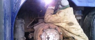
Work in the garage
A car requires continuous attention, care and skill from its owner.
The engine must operate without interruption in different modes and in any weather. Chassis - to ensure movement in space on any road and at any reasonable speed. Instruments - provide accurate information about the condition of the machine. The salon is always clean and comfortable. And the appearance of the car must be impeccable, because it gives the first characteristic to its owner. And to meet all these requirements, the car owner must have the appropriate knowledge and skills:
- understand how the engine works;
- understand electricity;
- be able to adjust the chassis;
- disassemble and assemble the transmission;
- and many many others.
You can't get here on enthusiasm alone. It is necessary to have the appropriate tools and equipment for the job. And in order to be able to get to any point of the car, you must have either an inspection hole, or a lift, or both at the same time.
Types and models
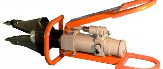
There are several options for traverse jacks.
- Hydraulic car lift with manual drive. This mechanism has a manual pump, thanks to which it lifts quite a significant weight, but at the same time to a small height. This mechanism is characterized by a fairly affordable cost.
- Pneumohydraulic car lift. This device is connected to the pneumatics of the service center and thereby frees the worker from performing manual work. To start the jack, simply press a button.
- Pneumatic traverse. Such scissor jacks today represent the most advanced mechanism. To work with it, a car mechanic does not need to make any effort to lift the car, even a multi-ton vehicle. The lifting capacity of this jack is quite simply determined from the calculation that to lift each ton, a pressure of about 2 atmospheres is required.
The range of pit lifts on sale is varied and makes it possible to choose a device that will fully meet the existing needs of the service station. Modern traverses differ:
- clearance;
- lifting height;
- maximum load;
- size;
- drive type;
- load capacity;
- paw span;
- degree of reliability.
Domestic and foreign manufacturers in the production of pit mechanisms use the most modern technological solutions and materials that ensure the safety and reliability of the device. In any case, the choice of a particular design is largely determined by the comfort of its use in each specific situation.
The hydraulic jack for the inspection pit is of greatest interest as a budget option for service station equipment. Such a device can be used to lift small-sized vehicles whose weight does not exceed 2.5 tons. Among the disadvantages of hydraulics, it is necessary to note the need for constant monitoring of the oil level in the system, as well as the need for periodic lubrication of all articulated joints.
The pneumatic traverse does not require special technological maintenance; it can lift machines weighing up to 6 tons.
A pneumohydraulic traverse, depending on its design features, may differ in load capacity parameters. It is easy to operate and does not require expensive maintenance.
Depending on the design features of pit jacks, certain options are distinguished.
- Two-stage mechanisms with a pair of grabs placed at different heights. This mechanism combines low-lift and traditional jacks.
- Low arm lift. Its distinctive characteristic is a picking arm protruding to the side, which is capable of catching a load under its lowest fragment. By the way, this is where another name for the mechanism came from - the hook jack.
- Low-profile traverse - used to lift cars with low ground clearance.
welcome to Russia
DIY garage lift photo
Traverse into the pit with your own hands
Pneumatic traverse for the pit – Metal Forum
hydraulic cylinder kun 80.40 630. connector
Pneumatic traverse 2000 kg TPO 300 in Chernigov, I offer services, car repair shops in Chernigov - 1371290, chernigov.avizinfo.co
Pneumo-hydraulic traverse Trommelberg TXBJ3000P – “Tech-Auto” technical
Other equipment for business, ready-made business, etc.
to the pit with your own hands
Pneumatic axial traverse TPO-600.
How to make a jack for a pit Do it yourself Review of repair methods
Traverse, pit jack for lifting a car
Pneumatic traverse 625 price 33,600 rub.
Pneumatic traverse TPO 300, price - 8,500 UAH, Krivoy Rog, used, advertisement, sell, buy.
Pneumatic traverse for the pit – Metal Forum
Manual car lift (traverse) Silver TS K-2, price RUB 2,242.27, buy in Minsk - Deal.by (ID# 6536118)
TPO 300 U - Traverse - Wheel alignment
Pneumatic traverse for the pit – Metal Forum – Page 2
Do-it-yourself traverse for a pit
MEGA MA-21 at the best price in Spetskomplekt in Murmansk
Peculiarities
The success of any service station directly depends on the ability of its owner to provide its customers with the widest possible range of services provided. At the same time, the quality of vehicle diagnostics and repairs directly depends on the technical equipment of the service center. Since the adjustment of the wheel alignment process, as well as the main part of the work carried out on servicing the chassis, is carried out in the inspection pit, the presence of a special lifting device - a traverse - is considered an indispensable condition for working at the station.
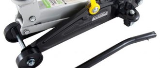
If a regular standard jack is enough for a car enthusiast to perform some everyday manipulations, then in the conditions of professional repair and service a more serious mechanism is required - it is called a pit jack, it is also called a ditch jack or an axial traverse.
Using a traverse is considered the most optimal and practical way to lift a car in a garage, where the dimensions of the room, as a rule, do not allow the installation of any other universal car lifts for passenger cars. Often, inspection pits serve rather as a successful addition to such lifts and may be of interest as a workplace for performing unscheduled minor vehicle repairs.
And if we are talking about trucks, then the only mechanism that can raise the rear or front axle of a multi-ton unit is a powerful pit jack. In fact, the traverse is one of the elements of a four-post, scissor or plunger lift, which is an alternative to the traditional inspection pit. Such a lift is fixed on pre-prepared guides; the peculiarity of their design ensures free and easy movement.
The main purpose of any pit traverses is to raise the front or rear axle during:
- carrying out plumbing and diagnostic work on the undercarriage;
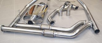
- performing inspection and repair of the underbody, as well as fuel and exhaust systems;
- adjustment of the wheel alignment mechanism.
DIY garage lift
For use in the garage, it is possible to make a kit for lifting a car with your own hands. You will need the necessary components, tools and plumbing skills.
A homemade lift is made using the following parts:
Steel corners measuring 8x8x1 cm, for making a stable structure. Worm type gearbox. A new product can be expensive; it is usually selected during disassembly or removed from a non-working mechanism
It is necessary to pay attention to the load capacity, the indicator starts from 350 kg, the transmission force indicator is 60 kg. A steel plate with a minimum thickness of 1 cm is removed from old equipment. Set of bolts, mounting hook, star-shaped keys. Several iron chains with a link diameter of 2 cm or more. Weak chains will not withstand the load, you should pay attention to the quality of the product, some materials can stretch during operation. Steel cable, 5 mm thick.
Assembly and installation of components occurs in the required sequence, following the proposed instructions. The steel corners are fastened to the walls in the opposite direction from the hood of the car. On top of the corners for the lift, a steel plate is installed with your own hands. The connection is made with prepared bolts. Next, you need to install the worm gear, securing it with a key on the drive shaft. A key of smaller diameter is installed on the output shaft of the gearbox.
DIY chain lift
Holes suitable for the diameter of the chain are made in the plate, after which the chain mechanism is installed
It is important to pay attention to safety; holes are made in the frame at a certain distance, and a locking mechanism is inserted into them
Features of operation of such a lift
The use of a worm-type unit during operation is suitable for lifting a car engine or load-bearing parts. The procedure for using a self-made car lift is simple; you must follow these steps:
- Remove engine mounts, bolts, nuts.
- Afterwards, the steel cable loops are supplied and the structure is coupled.
- The drive shaft rotates by turning the chain; with a little effort you can slowly lift the part to the desired position.
Worm type garage lift
After lifting, it is necessary to remove the car from the work area by placing a table under the engine. It is possible to make a stand or table with your own hands; the design must be durable and withstand heavy loads. Convenient to use is a table on wheels, which allows you to move the part in the required directions.
If the car is too big
Repairing large vehicles is not uncommon; wheel size and ground clearance may not allow you to raise the necessary parts to the required height. The process takes place with an assistant, who pulls the part onto a pre-prepared table. The gearbox rotates with the opposite side to the installed element.
Car lift for large cars
Such situations lead to thoughts about improving and modernizing a car lift for a garage with your own hands. It is possible to manufacture a movable structure that will make it possible to move the lifted part to the required distances. It is possible to make an aggregate installation with an electric motor on a reduction gear, in which case it can be a real crane for lifting large-sized mechanisms.
Traverses (pit jacks)
A crossbar is a lifting device that is used in conjunction with a four-post or scissor lift or on a pit to partially lift a vehicle. It is used for wheel alignment and general plumbing work. According to the type of drive, they are divided into traverses with manual and pneumohydraulic drive.
The Servo company offers hydraulic traverses (pit jacks) from the following manufacturers:
Auto repair shops mainly use hydraulic traverses or ditch jacks.
With the help of hydraulic traverses, wheel alignment is adjusted, diagnostics, repair or maintenance is carried out on the suspension of any type of vehicle within the established load capacity. Depending on the location, the hydraulic traverse is installed on a car lift or on an inspection hole.
Traverses (pit jacks)
Ditch jacks, or in other words - traverses - are equipment used by car services, car workshops, and service stations during the repair of a vehicle's chassis, to lift its front and rear parts, and for wheel alignment adjustments. Pit jacks (the same traverses) can be installed both on a car lift and in an inspection ditch, which is how they are classified - a traverse for an inspection pit and a traverse for a lift.
In addition to installation on auxiliary lifting equipment installed on a pit, it can also be installed on a four-post lift for hanging one automobile axle.
An auto service inspection ditch that is not equipped with a crossbar cannot be considered a full-fledged piece of equipment, since almost seventy percent of all work on a car requires hanging the chassis. Without it, by the way, it is impossible to carry out the alignment. It is for this reason that the traverse must be purchased together with installations that regulate wheel angles.
Regarding the repair of larger vehicles - buses, trucks, etc. - here the pit jack plays a very important role, being considered the main lifting unit. You can also use rolling columns when lifting trucks, but they are several times more expensive than pit jacks and do not differ much in efficiency.
Pit jacks can be pneumatic-hydraulic (quite expensive, they begin working, or rather lifting, after connecting to a pneumatic generator and pressing the traverse button) and hydraulic manual (they cost slightly less than the first option; they lift the load by manually pumping a hydraulic pump into the horizontal plane).
It is worth noting that this equipment is capable of lifting two car wheels at the same time, which is very convenient when performing wheel runout compensation operations.
The main characteristics of such a device include: • Lifting height, which ranges from thirty to fifty centimeters; • Load capacity – from one thousand and a half to thirteen and a half thousand; • Paw span – from eighty to one hundred and fifty centimeters.
As a rule, the pit jack kit includes an automatic locking device, which is released using pneumatics; automatic safe lowering system; and a valve producing maximum pressure.
DIY garage lift
A wide range of locksmith operations are not available to car enthusiasts in a regular garage due to the lack of special equipment.
But you can expand the range of your capabilities with the help of a traverse lift, designed for convenient work with the chassis and power unit with your own hands. Photo drive2.ru
Manufacturing materials and processing methods
The vast majority of car lift parts can and should be made from rolled metal. This is convenient, because this kind of materials is available at every metal warehouse, you can purchase exactly the required quantity, and most importantly, some elements can be replaced with other types of rolled products while maintaining the equivalent section.
Some parts have requirements for primary use, so some items will have to be purchased. First of all, a profile pipe of two sizes, the thickness of the smaller one should, with a minus millimeter tolerance, be equal to the internal dimensions of the larger one, for example, 40x40x5 and 50x50x4 mm. On average, no more than two meters of each type of pipe will be required.
Photo shod-razval-help.ru
It is advisable to make the remaining parts from a more massive assortment: channel, T-bar or angle steel. The base of the frame can be assembled from a 14U or 16U channel by connecting two sections in parallel. The channels can be replaced with pieces of angle steel connected by a solid weld with a reinforcing lining.
At the bottom of the frame, the choice of materials is absolutely free. In total, it takes about 6 meters of 63x4 mm angle steel, but it can be replaced with almost any materials of the same cross-section. Additionally, you will need several pieces of hot-rolled steel pipe, round timber of 40X steel or similar, as well as sheet steel for making gussets.
Purchased parts and additional features
In addition to the profile pipe, you will have to spend money on some parts of the lift mechanism. First of all, it is a hydraulic jack with a lifting weight of 4–5 tons.
There is no need to chase the maximum force; a much more important indicator is the length of the rod extension.
If the lift is being assembled for a service station, it is recommended to use one or two synchronized racks connected to a manual or electric hydraulic unit instead of a jack.
Photo chipmaker.ru
The lift is designed for use in inspection pits with a frame that can be used as guides. While working on the car, you may need to move the lift by choosing a different support point.
Therefore, the optimal design would be a crane-beam type design; it allows you to move the lift even with the machine. Roller skating rinks are required for free movement. Here you can go in different ways: install roller bearings, timing belt tensioner rollers, ready-made bearing units.
In any case, an important requirement is that the bearing must have plastic cage caps and be used in dry mode.
Photo drive2.ru
It is also best to first talk to someone who can do basic turning work. It will require thread cutting, pin sharpening, and some heat treatment. By investing up to 2 thousand rubles in the manufacture of these parts, you can significantly increase reliability, safety and ease of use.
Tip:
before you start making the lift, make sure the frame is intact. Seal the gaps with cement mortar; if the guides are not parallel, align them and provide additional anchorage.
Base frame assembly
As already mentioned, the base is assembled from two channels or pairs of angle steel that imitate them. Let us note once again that when welding the edges of angle steel, the seam must be strengthened with a pad at the bottom of the steel strip. The length of the channels must ensure their support on the shelves of the guides at least 20 mm on each side at the widest point of the pit.
The channels need to be folded parallel and their touching edges marked. Additional work is done on them: pockets 50 mm wide and 25 mm deep are cut out at a distance of 10 cm from the edge. Another pocket is cut clearly in the center, its dimensions are selected individually according to the outer size of the pusher bushing.
Before connecting the two parts of the platform, you need to try on pieces of pipe 50x50x4 mm long, 20–25 cm long, in the outer holes and make adjustments if necessary. If all the embeds are placed and the edges are prepared for welding, the connection can be made.
First, the channels are connected with tacks: at the edges on both sides, as well as at several points in the center. It is recommended to weld the edges of the shelves first and then weld along the flat side.
After welding, the part is checked to ensure flatness is maintained and, if necessary, straightened with a sledgehammer.
In the formed windows, you need to insert and fix by welding square glasses under the traverse posts and the centering sleeve. All elements must be flush with the plane of the upper platform. There is no need to completely scald the embedded parts right away; they must be able to move along both horizontal axes for alignment with the guides and pusher.
In the lower part, under the platform, there is a frame of the pushing mechanism, made in the form of a parallelepiped 80–100 cm long. The vertical parts must be welded from the inside to the outer edges of the platform, maintaining parallelism.
The lower connections between the verticals, located across the long side of the pit, connect the racks to form two U-shaped frames. The lower edges of these frames are connected to each other by two equally massive parallel inserts.
They must be positioned in such a way that the resulting horizontal shelves allow the jack to be installed freely and safely. In the resulting structure, the following places are reinforced with scarves:
- fastening the racks to the site;
- connection of racks with lower inserts, gussets are installed externally along all edges;
- places of insertion of glasses and bushings. Here the gussets are welded to the platform, but not to the mortise elements.
It's time to put the base on the rollers. Of all the varieties, we recommend sealed roller bearings. Under them, pins with necks at the ends need to be machined from 40X steel: the diameter is suitable for fitting the bearing with a tension of 0.01 mm. Making grooves for the retaining rings will be unnecessary.
The necks should initially be machined to a tolerance of 0.1 mm; in the wide part, with a distance of 10 mm from the edge and the neck, two 4 mm radial holes with a countersink should be drilled, preferably in a vice and in one installation.
Then the parts need to be hardened to a hardness of 40–42 HRC and the journals need to be finely turned.
The rollers are attached to the frame using sections of raw pipe welded horizontally on the outer sides of the platform. The length of the tubes should be 5 mm less than the distance between the holes in the fingers.
The installation height must be chosen in such a way that on the rollers the lower edges of the platform ribs deviate from the guides by 5–7 mm.
The bearings are placed on the rollers by hot pressing, then the axle shafts with rollers are inserted into the tubes and cottered.
Making a traverse
The traverse is easier to make; it consists of a central beam and two retractable arms. The beam is made from a pipe 50x50x4 mm, the length must correspond to the width of the pit. You need to drill a hole exactly in the center, the diameter of which is 2 mm larger than the thickness of the guide sleeve.
Thus, the same bushing is welded into the traverse as in the platform, but with a blind hole. The depth of the hole should be half the total length of the glass, which, in turn, should be 30–40 mm greater than the thickness of the beam, that is, up to 100 mm in our case.
The fastening is temporary, with two points on the top side.
Pieces of pipe 40x40x5 mm are inserted into the beam on each side, the length of each should be half the length of the central part of the traverse. The outer edges of the wings are blanked, then bushings with internal threads of 14x1.5 mm are welded to them vertically. The bushings are designed for screwing in height-adjustable stops.
You need to insert guide pieces of pipe 40x40x5 mm into the cups of the platform. Their length can be arbitrary, but usually 80–100 cm is sufficient. The guides are wedged in glasses with a gap uniform on all sides, using paper folded several times, and then placed at the same height.
A traverse beam is placed on top and welded. After this, you need to check the freedom of movement of the traverse vertically, simultaneously performing fastening by welding.
To prevent the guides from twisting while making the main seam, it is recommended to tie their lower edges with two pieces of reinforcement located crosswise diagonally. The fastening of the guides to the beam must be reinforced with small gussets.
At the junction with the guides, the gussets should have a height of no more than 40 mm and rectangular thresholds 20–25 mm long, acting as a backstop. Thus, the total height of the traverse above the floor is no more than 100 mm.
Assembly, fit and bells and whistles
The traverse must move freely in the guides along the entire travel height.
If necessary, you can mark the lapping areas, then remove excess metal using an angle grinder, or turn the guides or cups in the desired direction.
With periodic checks for smooth running, the cups are attached to the platform at all points of contact. After fastening, the guides are lubricated with grease.
Next, work is carried out on the pusher rod. It is better to make it from a round rod about 33–35 mm thick. The rod is inserted into the centering sleeve and thrust cup, and the sleeve gap should not be less than 2 mm for convenient alignment.
After installing the rod in the lift, you first need to weld the glass: apply a double seam on both contacting surfaces. Next, a sleeve embedded in the platform is welded. Its fastening should not be too strong; it is much more important to do a good job of eliminating the distortion.
The movement of the pusher in the bushing is carried out dry.
To ensure reliable blocking of the lift, it is necessary to calculate the position of the racks under the platform so that the guides are exactly between them.
A vertical row of coaxial holes is drilled into the racks every 50 mm, and it is advisable to make a mark from the lower ends of the guides as the traverse rises. Long pins are inserted into the resulting holes and secured with cotter pins.
The platform can be immobilized using square rods with beveled ends, which are inserted between the rollers with a gap of 3–5 mm.
Operating instructions and safety instructions
When a car enters a pit, the traverse is aligned with the reference points, adjusting the reach of the wings and the height of the stops. Next, the rollers are blocked. When the jack is removed, a push rod is installed, which is pressed by the screw rod of the jack. Then, using hydraulic force, the traverse rises to the required height, and the lift is blocked with pins.
If the jack does not provide the required lift height, it is drained, leaving the locking pins for temporary support. After this, the bar is changed to a longer one and raised to a higher position. For most situations, you need a set of a maximum of 2-3 rods of different lengths, which are connected to the jack rod with an adapter sleeve.
The car is lowered in the reverse order: first the locking pins are removed, then the jack is drained. If an extended rod was used, the descent is made with an intermediate position to replace the pusher.
If it is necessary to move the car along the pit, it must be lowered to a slope of no more than 3–5°, then remove the wedges from under the rollers and roll the lift manually or using a small winch.
This design allows for complete safe lifting of the car from both sides, however, for this it is recommended to consider a system of rigid connections between both platforms, for example, using long threaded rods.
Traverse to the pit - how does it work?
So, pit traverses are a combination of the following elements:
Loading …
- base, or carriage, on which all other elements are placed. It is a rectangular frame made of high quality steel. It can be additionally equipped with a roller system for moving both along the bottom of the ditch and along its walls (if there are special grooves);
- hydraulic or pneumohydraulic drive located on the carriage and driving the lifting mechanism. It is equipped with an impermeable hose and a pump, which is used to pump up pressure in the system (usually manually, although there are models that are controlled remotely);
Pneumatic traverse for pit
- scissor lift mechanism - a system of cross levers that moves as pressure builds up in the hydraulic system. In this case, the levers move towards each other, simultaneously lifting the platform with the load up. The number and location of levers may vary - depending on the required lifting height and load capacity;
- platform located at the top of the scissor system and directly responsible for lifting the load. Made from high-strength steel with a protective coating. To increase the lifting height, it can be used in conjunction with removable supports in standard or telescopic versions.
Hydraulic oil or compressed air pressure is used as lifting force, depending on the type of drive. The pressure in the system increases when the pump is pumped up; in this case, liquid or air flows from the tank/cylinder into the system through a sealed hose. Next, the drive begins to push the pistons, which activate the lifting mechanism.
When the rise is completed to its full height, the pumping stops, the hose is disconnected from the tank/cylinder and the valve is moved to the reverse position. After completion of work, the pressure is completely relieved from the system.
We recommend to buy
Popular models
Nowadays, auto repair shops use a large number of ditch lifts. The most popular models: P-263, P-114E 10, P-263 02 and others. Let's look at the characteristics of some of them.
P-263
The P-263 ditch lift is used for repairing cars, trolleybuses, and buses. It inspects and repairs the front and rear axles of cars in an inspection ditch. The design ensures stable lifting of the machine by synchronizing the rotors. This type of lift can be manufactured with electric or manual lifting. The racks contain load-bearing screws. There is a braking system.
Technical characteristics of the ditch lift P-263:
- engine electric motor power - 3 kW;
- weight - 615 kg;
- load capacity - 8 t;
- stroke of the working mechanism - 500 mm;
- ditch size - 1100x1200 mm;
- lifting height - 135 mm;
- maximum stroke of the rod is 390 mm.
P114E-10
The ditch lift P114E-10 is used for repairs over the inspection ditch of bridges of cars, tractors, buses, and agricultural machines. The device is mounted on the ditch. The method of its movement is manual. The trolley with a hydraulic cylinder and pump moves both across and along the ditch. There are grabs of different sizes. Safety is ensured by hydromechanical safety units. This ditch lift for trucks is manufactured according to the size of the ditch.
Specifications:
- load capacity - 10 t;
- control - manual hydraulic drive;
- there is a mechanical safety device;
- lifting height - 750 mm.
Other
The ditch lift P-263-02 is used for repairing vehicles. Load capacity - 10 tons. Made for a trench 1100 mm long. There is protection that ensures fire and electrical safety of the structure.
The device moves manually along rails located at the bottom. Equipped with a reliable multi-level security system. The working nuts are characterized by increased strength. The force when moving on rails is 20 kg.
Specifications:
- maximum stroke of the working mechanism - 500 mm;
- ditch dimensions - 1100x1200 mm;
- electric motor with a voltage of 380 V and a power of 4 kW;
- device dimensions - 940x1070x1270 mm;
- minimum lifting height - 70 mm;
- weight - 655 kg.
How to make a viewing hole in the garage
Once you have decided on the dimensions and what material you will make the walls from and how thick they will be, you can begin marking the pit. This can be done using pegs driven around the perimeter. The second option is to stretch a twine/rope between the stakes driven into the corners. According to the markings, we begin to dig a pit. The earth is usually taken out and temporarily stored near the gate.
Made of brick: step-by-step photo report
While excavating, monitor soil moisture. If you have reached the design depth (required + thickness of the floor screed), but there is still no moisture, you can do without waterproofing. Those who do not want to take risks can be advised to immediately lay down the film.
We level the walls. There is no need to achieve ideal geometry, but there should be no noticeable humps or holes. We also level the bottom of the pit and tamp it, compacting the soil well. A hand tamper is usually used. A layer of crushed stone is poured onto the bottom (twice 5 cm each), each layer is also carefully compacted. Next comes a layer of sand. 5 cm is enough. The sand is moistened and compacted to a high density so that the foot does not leave imprints. Next we lay the waterproofing film.
We even it out well, tucking it into the corners. We lay the panels with an overlap of 15 cm, which we glue with double-sided tape. To prevent the edges from rolling, we press with available materials - boards, stones.
We lay a layer of insulation on the bottom, and a reinforcing mesh of wire on top of it. We fill all this with concrete grade M 200. The thickness of the layer is at least 5 cm. To make it easier to navigate when laying, we make marks on the film by which you can control the thickness of the layer.
If you use Portland cement M 400, the proportions will be as follows: 1 part cement, 3 parts sand, 5 parts medium and fine crushed stone.
We wait several days until the concrete gains 50% strength. The exact period depends on the temperature. If it is around +20°C, you will have to wait 5-6 days. If +17°C is already two weeks.
Let's start laying out the walls. It was decided to make it in half a brick. We used used bricks, about 850 pieces were used (pit size 4.2 * 0.8 * 1.7 m). The walls were laid out in a circle up to the level of the elbow.
It was decided to make a niche for the tool at a level of 1.2 meters from the floor. Its height is 3 rows of bricks, the top is covered with a treated board.
To avoid having to lay out a brick niche, a metal liner is inserted. A box is welded to suit the size.
Next, the walls were driven almost level with the garage floor. Part of the walls was replaced with two sections of channels. If necessary, jacks rest on the bottom. A metal corner with a 50 mm shelf, steel thickness 5 mm, is placed on the top row.
The corner is unfolded so that one of its shelves hangs down, the second covers part of the upper surface of the brick. To prevent the wall from collapsing under load, embeds are welded to this corner, which are then connected to the reinforcing belt of the concrete floor in the garage.
Next, preparatory work was carried out to install a concrete floor and it was poured with concrete.
Features of making concrete walls
When casting concrete walls, it is necessary to make formwork. It is easier to make it from sheet material - construction moisture-resistant plywood with a thickness of 16 mm or more, OSB. Shields of the required size are knocked down and reinforced with bars on the outside. They are necessary to prevent plywood or OSB from bending under the pressure of concrete. First, the outer parts of the formwork are installed. If the walls of the pit are smooth, there will be no problems. You simply lean them against them and place them level.
Then the internal formwork panels are installed. There should be a distance of at least 15 cm between them. To prevent the walls from deforming during the pouring process, spacers are placed between them.
It is advisable to fill the filling at one time. The poured portions must be bayoneted or treated with a submersible vibrator for concrete. The formwork is removed after two to three days. Afterwards, you can install a corner with welded embedded rods (strips) and begin pouring the floor.
Do-it-yourself traverse lift to the inspection hole in the garage
The following solutions were used as materials. For longitudinal beams, channel No. 8 was used, for transverse beams - channel No. 6, for platforms with holes for guides - corrugated pipe 50x100. The material was selected taking into account the entry of the smaller channel with its edges into the larger one, and the profile pipe into the smaller channel, which ensures additional rigidity of the structure.
Length – 500 mm, width between the edges of the cross beams – 820 mm. The distance between channel No. 6, where the pipe enters, is 340 mm. The distance between the guides is 600 mm. The length of the guides themselves is 700 mm; 32 pipes were used for their manufacture. The lifting beam is made in the form of a kind of profile pipe, which is welded from channels No. 8 and No. 6 - they are inserted into one another. The length of the beam is 1050 mm.
The jack is a two-rod jack, made in China, according to the stated characteristics - 6 tons. For the platform for the jack, 3 pieces of channel No. 6 were taken. A 6 mm reinforcing plate was welded into the end of the platform on the sides. The “wheels” are bearings 180604, size 20x52x21 - 2 pcs. on each of the corners. M20 bolts are used as axles; the part without thread has a length of at least 40 mm and a thickness of 20 mm. 30 mm spacers are inserted between the bearings and the frame. They are here because the inspection hole for which this structure is made is filled unevenly, with a floating distance between the edges. In order for the traverse to move more smoothly along the pit, horizontal guides are provided in the form of small bearings 608 (they are in the photo where the structure is placed on the pit).
also made several pneumatic traverses for a local service station a little earlier:
The device is made according to the same principle, but with some difference - with an air spring instead of a jack. A screw from a jack is welded to its body, due to which the height of the pick-up can be adjusted.
Included with the traverse were anti-recoil shoes - 4 pcs. In the shape of a right triangle, the size of the legs is 150 and 280 mm, the hypotenuse is 280 mm. Material – strip 80 mm long.
For welding, 4 mm ESAB electrodes and an industrial welding trans were used, but in some places I used P/A.
Source: https://www.umeltsi.ru/avto_samodelki/5312-podemnik-v-garazh-traversa-na-smotrovuyu-yamu-svoimi-rukami.html
What materials are they made from?
The inspection pit in the garage (its walls) is lined with bricks, heavy building blocks, and made of monolithic concrete. If we talk about bricks, it is better to use ceramic bricks: they are not afraid of moisture. The walls are made of half a brick or brick. The wall thickness, depending on the laying method, is 12 cm or 25 cm. This must be taken into account when marking the pit.
Brick can be used on dry, dense soils. The groundwater level must be low. If the water comes up high, it is better to make the walls of the pit from reinforced concrete.
Building blocks also need to be selected those that are not afraid of high humidity. These are concrete blocks. The rest, if used, must require external waterproofing, and this is not a guarantee that they will not crumble, especially if groundwater is located close.
With a concrete inspection hole, everything is simpler: concrete is not afraid of moisture, it only makes it stronger. To fill the walls, concrete grade M 250 is used; for the floor, M 200 is sufficient. Why is this so? Because during winter heaving the main load falls on the walls. To prevent them from “collapsing”, a margin of safety is required, which is achieved by reinforcement and the use of high-strength concrete. By the way, to avoid heaving of the soil under the garage, you need to make a good blind area so that the water leaves and does not soak into the soil.
The wall thickness when filling the inspection hole with concrete is from 15 cm. Stacks must be reinforced. To do this, use a ready-made mesh with a wire thickness of 5-6 mm and a pitch of 150 mm (if the groundwater is deep) or knit a frame from reinforcement with a diameter of 10-12 mm. The reinforcement installation step is 20 cm. For greater strength, you can make a single rod for the bottom and walls, bending it accordingly.
Waterproofing methods
An inspection pit in a garage can be protected from moisture penetration in two ways: with the help of external waterproofing, which is carried out exclusively during the construction process, and internal, which can be done during operation.
External protection
If in the place where the garage is being built the groundwater is deep, lower than 2.5 meters, and even in the spring or after heavy rains it does not rise higher, you can do without waterproofing. On the other hand, the hydrological situation is constantly changing, and where it was previously dry, water may appear. If the inspection hole in the garage has already been built, external waterproofing cannot be done. All that remains is to use deep penetration impregnations to reduce the hygroscopicity of the walls. Therefore, if possible, do external insulation in any case.
How to prevent moisture from entering the inspection hole in the garage? Most often, waterproofing films or membranes are used (butyl rubber, aquaizol, etc.). They are laid in sheets, covering the pit from one edge to the other, with 10-15 cm released from each side of the pit onto the garage floor. The panels are laid overlapping. They must overlap by at least 15 cm. To obtain a more airtight joint, they are glued together with double-sided tape, possibly in two stripes - at the beginning and end of the “overlap.” The film is well straightened so that it fits snugly against the walls of the pit.
During further work, it is important not to damage the membrane
Internal waterproofing
Internal waterproofing is usually the impregnation of walls with coating waterproofing. If possible, use a composition for swimming pools. It creates a waterproof, dense film that closely resembles rubber. It is blue in color and washes well after hardening. It is better to treat the walls with this composition twice, or more.
Another option is a cement-based deep penetration primer. The polymer particles contained in it block the capillaries through which moisture penetrates through the thickness of the material. One such treatment significantly reduces the hygroscopicity of the material. In the case of water in a garage pit, at least twice the treatment is required (and preferably more).
Caisson device
There is another option to escape from the ground - to make a metal caisson. A box of appropriate dimensions is made from sheet metal, treated with anti-corrosion compounds, and then installed in a pit. If the welds are made airtight, there will be no water, but another problem may arise. If there is a large amount of water, it can squeeze out the caisson. They say that it "pops up".
To avoid such a situation, corners and rods are welded to the sides of the caisson from the outside, which go 1-1.5 meters into the ground. So that the volume of excavation work is not very large (the foundation pit, taking into account these spacers, turns out to be large), you can cheat. Before installing the caisson, drive corners or metal rods into the ground, letting their ends out. You can weld them to the caisson body after installation. The pit will still have to be made larger (you need to cook it from the outside), but its dimensions will still be smaller. The second advantage of this method is that the rods will be driven into dense soil, which means they will hold the caisson better.
Another way to prevent the caisson from “floating up” is to make a hole in the wall at a certain height. If the water rises to its level, it will begin to pour inside. The water can subsequently be pumped out, the main thing is that everything remains in place. An inspection hole in the garage, built according to this principle, stood for more than 20 years - until the metal rusted.
Water collection pit
If the pit has already been built, and coating waterproofing or impregnation did not give the required result, it is necessary to either install a drainage system around the garage or collect water in one place. To do this, a pit is made in the garage inspection pit, at one of its ends. Water accumulates in it, from where it is pumped out. In order for the system to operate in automatic mode, a water presence sensor is installed, which, when triggered, turns on the pump.
Formwork is made under the pit and filled with concrete. Then they waterproof the pit along with waterproofing the entire pit. For reliability, you can also put a metal caisson inside.
Since it is not possible to completely get rid of dampness in this case, a boardwalk is knocked down onto the floor of the pit. To prevent the boards from rotting, they can be soaked in waste. If you don’t like its smell, take a special impregnation for wood that has direct contact with the ground (Senezh Ultra, for example).
DIY inspection pit lift - Metals, equipment, instructions
To repair or maintain your car yourself, you need an inspection pit or a lift. It is not possible to dig a hole in every garage, so many car owners are thinking about installing a lift themselves. After reading the article, you will learn how to make a car lift with your own hands, what you will need for this and how much such work will cost you.
What types of lifts are there?
There are three main types of mechanisms that are used to repair cars:
- hydraulic;
- chain;
- screw.
Lifts are also divided according to the method of lifting the car:
- scissor;
- platform;
- fork
The most popular type of lifts are screw fork lifts. They are based on a long threaded shaft made of tool steel that can withstand loads of up to 2–3 tons. However, making such a mechanism at home is almost impossible due to the complexity of making forks. Therefore, screw platform devices are more suitable for DIY manufacturing.
They are made in the form of two parallel channels, laid with ribs down and attached to screw drive mechanisms that provide lifting of the platforms. In such devices, the requirements for shafts are noticeably lower, because lifting is provided not by two, but by four shafts.
Their significant disadvantage is the need to use a jack to repair the suspension, because the wheels of the car do not hang in the air, but stand on channels.
Often forklifts and platform lifts for cars are made with a chain drive. In terms of their characteristics, they are in no way inferior to screw ones, but they are more difficult to make with your own hands.
After all, coordinated operation of all drive electric motors, as well as braking devices, is required.
To make scissor lifts, a hydraulic drive is most often used, although some DIYers are experimenting with a chain or screw drive.
Lift - do it yourself or buy a used one
The main problem that everyone who wants to make a car lift on their own faces is the high cost of parts, which is why it is much cheaper to buy a used device. After all, hydraulic cylinders of sufficient length and carrying capacity cost tens of thousands of rubles.
Custom, durable tool steel worms (threaded shafts) will cost at least the same.
As a result, the cost of building the simplest scissor lift with your own hands reaches 100–120 thousand rubles, while the cost of new Chinese devices of various types starts from 80 thousand rubles.
In addition to cost, there are two more factors that cast doubt on the feasibility of making a lifting mechanism for a car with your own hands - reliability and safety. The weight of even a small car often exceeds one ton.
If a car lift can't handle the load, the car will fall on the person underneath it. Such cases are known. All of them ended in death or severe disability.
A car may fall off a lift for the following reasons:
- the weight of the machine turned out to be more than the drive or actuator can support;
- the locking device turned out to be of incorrect design;
- the locking device could not withstand the load;
- The lift supports are insufficient or incorrectly secured.
To make a lift with your own hands, you have to either take a ready-made diagram, hoping that its author has carefully calculated the strength of all the parts, or carry out these calculations yourself. Only a highly qualified engineer can do this kind of work; an ordinary car enthusiast cannot do it.
In addition, it is necessary to calculate how much load the drive and brake mechanism can withstand. If any of these calculations are made incorrectly, the car lift turns into a deadly trap. No less important is the calculation of the basis of this mechanism.
It is not enough to simply pour a thick layer of concrete, because it is necessary to provide fastenings located in strictly defined places.
Search for parts
If you nevertheless decide to build a car lift with your own hands, and you are not afraid of the dangers of this homemade product, then start selecting parts by searching for the drive mechanism and stopper. These parts can be found in the following places:
- stores selling components for special equipment;
- enterprises that have old construction equipment on their balance sheet;
- enterprises that are updating their fleet of woodworking or metalworking machines;
- collection points for ferrous and non-ferrous metals.
For a scissor lift, you will need two hydraulic cylinders of suitable power and length, a compressor for them, and hydraulic hoses. The scissor circuit is the easiest to manufacture, but it is impossible to make a reliable brake in it. Therefore, if a hose bursts or one of the cylinders leaks, trouble cannot be avoided.
Shafts and electric motors with gearboxes suitable for platform or fork lifts are easiest to find where old machines are replaced with new ones. This will cost much less than ordering worms from a turner.
And the stopper of such mechanisms is not complicated - a helical bar with a lock, made of steel 1-2 cm thick.
Conclusion
If you still decide to take a risk and make a car lift with your own hands, then before choosing any scheme and starting assembly, find those who have already made such a device.
See how it works, make sure it is safe. After all, you are not risking your car, but your life.
If, when the car falls, one of your family members is under it with you, then you will put his life at risk.
Do-it-yourself car lift for a garage: manufacturing instructions, types
Many car owners, having the appropriate knowledge and skills, are ready to begin repairing the car engine on their own. To do this, the machine engine should be pulled out of the hood and installed back at the end of the work. It’s difficult to do this, and it’s impossible without a special lifting device .
But you can find a way out of every situation. And if you have a garage, you can take advantage of the experience of many craftsmen and make a car lift for the garage with your own hands.
Materials for work
To produce a motor lift, prepare the following materials and tools:
- a pair of metal corners 7.5 × 7.5 × 0.8 cm;
- steel plate 1 cm wide;
- gearbox with a coefficient of 60 and a load capacity of 300 kilograms;
- bolts;
- chain, 2 pcs.;
- “star” key (suitable for an ordinary moped), 2 pcs.;
- hook.
Making a lift
The very first thing is to select a lift model and develop its drawings. To manufacture any type of lift with a mobile frame, you must first acquire materials and tools. The materials needed are a steel profile - an angle or channel of size 45-55 mm, round timber for the wheel axles to suit the size of the bearings, a rod for the hinges.
If a design with a worm drive is chosen, then the lead screw should either be selected ready-made or ordered from professionals. You can't do it yourself at home. For the hydraulic lifting option, a suitable hydraulic mechanism must be found. The tools you will need are a large bench vice, a grinder, a hacksaw, keys, and screwdrivers. You must have welding equipment and be proficient in welding techniques.
Tipper
The easiest option is to install the machine on its side. Sometimes this is enough to perform many suspension jobs. The base frame is welded from a 50 mm corner.
PHOTO: grifon-kamaz.ru Tipper for placing the machine on its side
The device is placed under the bottom of the machine, then the lead screw is rotated, and the machine is installed on two side wheels. The device is lightweight and can be moved by dragging.
Mobile engine lift
Sometimes it is necessary to remove the engine from the car and transport it to a workbench. A small mobile crane is suitable for this. The boom is lifted using a small jack. Its manufacturing technology is the same as that of the tipper. To move the crane along the floor, it is mounted on rubber-coated bearings.
PHOTO: podelki.orgMobile engine lift
Floor mobile lift
The lift may need to be moved during operation. This means that such a lift must satisfy two requirements - it can support a car and it can be moved quite easily, even without a car.
It must be moved when installing it under the machine and when cleaning it after finishing work.
PHOTO: ok.ruInstalling a lift under a car
Pit jack
The pit jack is considered the height of perfection.
PHOTO: YouTube.comMobile lift built into a pit
Although it is mounted in a pit, and it is impossible to quickly remove it from there, it is still movable: its loading platform can move both along and across the pit along with the car installed on it.
The lift has retractable “legs” that allow you to install a machine with any track width on it.
PHOTO: YouTube.comExtendable paw stands
The “feet” have screw-out stops.
PHOTO: YouTube.com Screw-out stops
The support beam can move across the axis of the pit, and the entire structure runs on rollers along the pit.
PHOTO: YouTube.comTransverse movement of the support beamPHOTO: YouTube.comRoller with hub
PHOTO: YouTube.comMoving the bed along the pit
To make a good, powerful lift, you need to purchase a 100 mm channel, a corner with a wall size of 50 mm, and profile pipes of 50 and 40 mm. The lifting mechanism is a 12-ton jack.
PHOTO: YouTube.comLifting the support beam using a hydraulic mechanism
The bottom of the machine rises 60 cm above the floor level.
You can install a smaller jack, but it will have a low lifting height. You will have to lift the car in several stages, placing thick plates under the jack.
PHOTO: YouTube.comVariant of a mobile ditch lift with a small jack
To complete the set, a movable hoist is placed above the pit.
PHOTO: YouTube.com Hoist in the garage
All parts are welded by electric welding.
Equipment for inspection pit
The inspection pit equipment for vehicle maintenance must be provided with several mandatory devices and systems. Mandatory equipment items should include:
- Wheel bumpers;
- Staircase with handrails;
- Lighting system with 12 or 36 volt power supply;
- Socket for connecting a portable lamp on an extension cord with lamps of 12 or 36 volts;
- Niche for tools;
- The edge of the inspection hole, designed for installing and securing ladders;
- Platform at the bottom of the inspection hole.
To install a lighting system, waterproof lamps with reliable shades made of durable, unbreakable glass are usually selected. Modern facade spotlights and LED lamps are best suited for this. Installation of such lamps is usually carried out tightly, in the wall, so that the lamps do not interfere with work. Another option for installing lamps is to install them directly into the floor near the edge of the inspection pit between the bumper and the edge of the pit. For this installation method, waterproof anti-vandal lamps are used, installed directly into the surface of the roadway or sidewalk to illuminate the facades of buildings.
A wheel bumper is constructed to prevent the car's wheels from driving into the pit. For this, a pipe with a diameter of 100 mm or a channel of the same width is usually used. At the beginning of the pit, near the entrance to the garage, it is necessary to make a bend to correct the direction of movement of the wheels, and at the end of the pit, it is necessary to make a wide bumper in order to limit the movement of the car outside the pit.
Advice: in order to get used to the dimensions of the pit and not go further than necessary, you can place visible landmarks on the walls of the garage, for example, vertical lines that are easy to navigate, or tie a tennis ball on a string at the place where the car should stop at the level of the car hood so that during the race it was possible to stop when the ball touched the hood.
Car maintenance work often requires changing working tools, which are not very convenient to place under the bottom of the car, and therefore you have to go down into the pit and up to the surface several times, which is not very convenient without a ladder with handrails. Typically, for garages with a small box volume, the ladder is installed near the gate so that there is a level front and a platform for working with tools near the engine. A stationary staircase with handrails and steps with wooden overlays is installed right next to the gate. But in order to work more comfortably, in addition to a stationary ladder, a portable ladder is welded from a square pipe or a pipe with a diameter of 25 mm, with the help of which it is easy to climb in the area of the hood of the car.
Inspecting a car often requires that the lighting fall from the side where it is convenient for a detailed inspection, which is why to work under the bottom of the car in the tool niche it is necessary to place an outlet for connecting a flashlight with a power supply of 12 or 36 volts. A DC voltage of 12 or 36 volts is not dangerous to humans, and therefore it is this voltage rating that is recommended to be used to power lighting in the inspection pit.
A tool niche is usually provided during the construction of the pit walls, in the case of masonry this may be a small niche to accommodate a jack, wheel chocks or other tools commonly used for working under a machine. For a pit whose walls are made by pouring concrete, it is recommended to use a metal box, pre-installed in place before pouring concrete, as a finished niche.
Typically, the inspection pit is covered most of the time with wooden panels, which not only makes it safe to park the car in the garage, but also prevents excess moisture from penetrating into the garage. Such shields are placed in guides made of metal angles, fixed along the edges of the pit. For panels, high-quality oak boards 50 mm thick, knocked down into panels 1 meter long, are usually used. But the stops are welded from a 50*50 mm corner in the form of a frame and installed on the top of the fill so that the inner edge of the corner is flush with the walls of the pit.
Such a support for shields can also be used to place a movable cart on bearings, on which both tools can be placed and used as a stand for a container with used oil when changing the oil in the machine’s engine.
And of course, a platform made of slats 2*2 cm 1 meter long for installation at the bottom of the pit; such a structure makes it possible to move safely without fear of falling on spilled oil.
Do-it-yourself traverse for a pit
You can make a pit traverse with your own hands, using an ordinary hydraulic jack as a basis. All that is required for this is a well-made drawing, which, in addition to overall dimensions, will take into account the expected loads and dimensions of the ditch, a certain amount of metal profiles (beams, channels and pipes), electric or arc welding, if necessary - wheelsets, bolts and nuts
Do-it-yourself traverse for a pit
If you are not strong in geometry, you can turn to a specialist to create a drawing, or look for a ready-made one on the Internet.
The finished design, of course, will not amaze with elegance - however, this is not required of it. The most important thing is performance, which, if executed correctly, will be excellent.
Techniques for safe operation of a lift in a garage
The use of a worm-type device in repair is important for lifting the engine of a vehicle or its main components. Using a homemade mechanism is not difficult, just follow these steps:
- dismantling motor fasteners, bolts and nuts;
- supply of steel cable loops for coupling mechanisms;
- rotation of the drive shaft by brute force chain;
- slowly lifting the part to the desired height.
After fixing the part, the transport is removed from the repair area. A table is installed under the engine. You can also make the stand yourself. The main thing is to create a durable structure designed to withstand the appropriate loads. A mobile table on wheels is considered optimal, allowing you to move the spare part in the desired direction.
Repairing large vehicles in a garage is not uncommon. However, not every mechanism is designed for wheel diameter and ground clearance. Therefore, to service such vehicles, an assistant is needed who will pull the winch to install the spare part on the prepared stand. The second person rotates the gearbox.
Maintaining the device in working order involves regular inspection of the main components - fasteners, reference areas, wiring, racks. During operation, do not exceed the permissible weight of the vehicle.
Vehicle repair shops are incomplete without a lift. Which one is better to choose is decided by the station owner or garage owner. The market offers a variety of models from Russian and foreign manufacturers. For example, an installed elevator for a vehicle pays for itself in 6 months, but purchasing such a unit for personal use is impractical. Taking into account your own skills and the availability of drawings, you can build a car lift yourself.
Pits and lifts
Normal work with the underbody of a car requires the ability to reach this very underbody.
You can do this in three ways:
- Place the car on its side on a regular level surface.
- Organize a hole under the car and work while standing in this inspection hole.
- Place the machine on a lift and raise it to the desired height as needed.
There is a fourth, hybrid option - the hole is dug shallow, and the lift has a small lifting height. But the sum of the depth of the pit and the height of the lift turns out to be above the repairman’s head.
Lifts designed to operate in the absence of an inspection hole are available with manual drive and mechanical drive - hydraulic and electric. Their common property is that they are relatively easy to move around the garage space on their own wheels.
Lifts that work in conjunction with an inspection pit are more complex in design, but they also move along the pit, and sometimes across it, without expending much effort.
Related article:
How to choose?
The main point that interests any car mechanic and service station owner when choosing a lifting mechanism is its load capacity. But there are other important technical parameters.
The height of the working stroke - everything directly depends on the installation location of the mechanism. It's one thing if you place the jack in a pit, but quite another if the equipment is part of a four-post or scissor lift.
Track width - you need to understand well that, ideally, the parameters of the inspection hole and the traverse should match. In practice, this does not always work out, so you have to look for a suitable mechanism or reconstruct the pit. However, the track width in the vast majority of models can vary, so the width of the supports becomes a slightly more significant parameter.
The weight of the pit lift is not particularly important, since such a jack is installed on skids, and the mechanic does not have to move it manually.
To learn how to make a pit jack with your own hands, see below.
Do-it-yourself lift for inspection pit - Metalworker's Guide
To service a car in a service station, a bunch of special equipment is used, from cheap to very expensive, completely inaccessible to a private technician or simply a vehicle owner who is used to servicing the car with his own hands. There are very highly specialized devices that can be useful to a private owner once or twice a year. And there are those without whom any repair or prevention is simply impossible. Car lifts are just that case.
Dimensions of the inspection hole in the garage
You will not find strict recommendations on the size of a garage pit. They are based mainly on the parameters of the car and their own height. The dimensions of the garage pit are selected based on the following considerations:
- The width should be sufficient for you to work comfortably in it. At the same time, it is limited by the distance between the wheels of the car - each wheel must have room to maneuver. On average, the width of the inspection hole is 80 cm or more.
- Its length depends on the length of the car. Add 1 meter to the size of the car. This is enough for comfortable work.
- The depth is calculated depending on your height: your height + 10-15 cm. In this case, you don’t have to worry about hitting your head. If you need to work with your arms raised for a long time, you can knock down a special stool of low height and stand on it. You can raise the floor in the inspection pit a little more using wooden ladders.
This is far from dogma. Everyone does as they see fit. Some people find deep holes inconvenient and they make them almost exactly tall, and sometimes even lower - 1.5 meters. If you take into account the car's ground clearance, from the floor of the pit to the bottom of the car it will be about 1.7-1.8 meters. You can do it this way.
Another point about length. Sometimes it is not possible to make a long hole. Then it is made approximately half the length of the car, driving it in front or back, depending on which part of the car needs inspection or repair.
Now about where to place the pit in the garage. Usually it is shifted slightly towards one of the walls, leaving a wide side for installing equipment, storing spare parts, etc. In this case, there must be at least 1 meter from the edge of the pit to the near wall.
That's all the parameters
Just note that we were talking about the final dimensions of the pit. When marking the pit, you will need to add thickness to the walls, and dig deeper to the height of the floor screed (if you do it)
Types of lifts
Car lift
Various designs have been developed for a personal auto repair shop - a block, a jack, a hoist, a hoist, etc. Mobile devices for lifting heavy objects are popular.
A small jack is a mandatory attribute of a car trunk. The mechanism allows for minor repairs in any conditions. Large structures are designed for installation in a garage and are used for large-scale work.
Block mechanisms are suspended from the ceiling of the room. The devices reduce the operator’s labor costs for lifting a vehicle or other load. Depending on the number of blocks, the need for strength is leveled. For example, the presence of 4 elements installed on the garage ceiling beam allows you to completely lift a passenger vehicle.
Tal is a single block system. The design of the hoist is similar to a combination of a hoist and a trolley that moves along a beam on top of the car. This mechanism can be equipped with motors - one for moving the hoist, the second for rotating the cable. The result is a miniature crane.
The best option for a DIY garage lift is a scissor or worm type design. This is due to its performance characteristics and ease of maintenance. Making it at home is a simple process.
Insulation of the inspection pit in the garage
If you spend a lot of time in the garage, then you will most likely have heating. In order to warm up faster, it makes sense to insulate the pit. EPS (extruded polystyrene foam) is best suited for these purposes. It can withstand significant loads, is not afraid of dampness, does not rot, and fungi and bacteria do not multiply on it.
The thickness of the EPS to create a noticeable effect is from 50 mm. Place it between the soil and the wall of the pit. Then from the outside to the inside the pit will look like this:
- waterproofing film;
- EPPS;
- wall.
Expanded polystyrene can also be placed under the screed at the bottom of the inspection hole. A reinforcing mesh is usually laid on top of it, and then concrete is poured.