The main difference is the connection
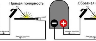
In the case of straight polarity, the welding cable is connected to the positive terminal of the machine, so that electrical charge carriers flow to it through the workpiece. The negative pole of the influx of charges is formed in the area of the welder’s main tool – the holder with the electrode.
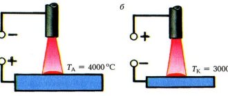
The described difference in direct and reverse polarity of connection to inverters has a significant impact on the temperature regime in the welding zone.
Thus, direct connection increases the temperature at the anode pole of the arc discharge ("+" sign) compared to the cathode contact ("-" sign). This effect determines the possible scope of application of direct polarity when carrying out welding work.
The direct direction of the current ensures the release of significant amounts of thermal energy from the workpiece. As a result, direct polarity can be used for cutting large metal structures and massive steel products with thick walls.
When turned back on, the picture of the distribution of the released thermal energy is completely different. In this case, excess heat is observed on the electrode of the welding inverter, and on the side of the workpiece being processed, its level noticeably decreases.
That is why reverse polarity is used in cases where it is necessary to minimize the risk of workpieces being rejected, as well as when carrying out jewelry-calibrated, precise work.
Reverse polarity is also used when welding thin-sheet materials and steels of varying degrees of alloying that are sensitive to overheating. The most widespread is the use of reverse switching current when working under submerged arcs, as well as in an environment of inert gases.
Direct and alternating current
In addition to the direct and reverse polarity of the voltage supply, the type of current (direct or alternating) has a great influence on welding. The dependence of the welding process in this case is manifested in the fact that when welding with direct direct current, the electrode burns out much longer.
The type and polarity of the current, as factors that jointly influence the characteristics of welding, makes sense to consider only for constant voltage.
When an electric arc is formed in alternating current mode, the concept of polarity is automatically excluded from consideration.
The influence of the type of supply voltage (DC or AC) affects the selection of welding equipment. It is expressed in the following contradictory factors:
- when working with an inverter on direct current, it is possible to obtain a better and more reliable seam;
- the same result is obtained when working with a semi-automatic machine;
- on the other hand, most electronic and automated welding systems are sensitive to the supply voltage and require a stabilizer;
- A conventional transformer converter does not have strict limitations in terms of supply voltage and can be started even with very low readings.
For this reason, if the operating network is highly unstable, it is best to purchase a conventional transformer unit operating in alternating current mode (sacrificing quality to some extent).
Otherwise, the electronic systems built into the inverters will automatically turn off at the most inopportune moment.
Influence on the choice of electrodes
The type of current also affects the choice of electrodes for welding. Thus, a unit operating on alternating current will be able to weld products only with electrodes specially designed for this purpose.
When working with such equipment, it is also possible to use universal consumables.
But this device cannot work with electrodes intended for use in direct current mode (UONII, for example). Note also that the inverter can cook with almost any consumables, but preference is usually given to universal rods.
Thus, the type of current, as a factor influencing welding procedures, determines the choice of a suitable apparatus and electrodes used in welding.
Current setting depending on the electrode
Now let's move directly to the electrodes and current settings. As we wrote above, the diameter of the electrode is selected based on the thickness of the metal. If you need to weld a part with a thickness of 3 to 5 millimeters, then use electrodes with a diameter of 3-4 millimeters. If the thickness is up to 8 millimeters, then an electrode with a diameter of 5 millimeters will be enough for you.
What about current? Everything is simple here.
When welding metal with a 3 mm electrode, the welding current should be from 65 to 100 Amperes. You might be surprised by the big difference in the numbers, but don't worry. You will choose a convenient value depending on the metal and its characteristics. For beginners, we recommend setting it to 80 Amps; this is the most universal value.
The strength of the welding current when welding with a 4 mm electrode can range from 120 to 200 Amperes. This electrode diameter is the most popular because it allows you to weld a wide variety of seams. It is widely used in industrial and home welding. Therefore, it is extremely important to learn how to adjust the welding current in this range.
If you plan to use an electrode with a diameter of 5 millimeters, then you will need fairly large welding current values. Minimum 160 Amps. The recommended value is 200 Amperes. To ensure continuous operation and a stable arc, we recommend using a semi-professional transformer.
But what if you are going to work with thick electrodes? Let's say 8 millimeters. Here you cannot do without professional powerful equipment. The minimum current value should be 250 Amps. But, most likely, in your work you will have to use much larger values, up to 350 Amperes.
Separately, we would like to say about compact inverter welding machines, which are now sold in every specialized store. They are loved by many home welders for their simplicity, compactness and reliability. But there is also a drawback: often such devices can only work with small-diameter wire, up to 2 millimeters. For such devices, a current of 40-50 Amps will be sufficient. We recommend purchasing models of devices that can smoothly regulate the current. Then the error will be minimal.
Do not set the amperage at random or based on unsubstantiated advice from other welders. This issue needs to be given due attention, otherwise the metal will either not melt to the required depth or will be burned through. In any case, the quality of the seams from such work cannot be called good or even tolerable. Your main advisor is GOSTs and other regulatory documents, which clearly define all settings. Study them, this is the only way you can get the right information.
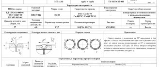
Below you can see tables that will help you adjust the welding current depending on the diameter of the electrode used. Set the settings on your welding machine from the first table if you plan to weld butt seams.
The settings from the second table, which you can see below, are more universal. You can start your first attempts to set up a welding machine with them. This table of welding currents will definitely come in handy, so write it down or remember it.
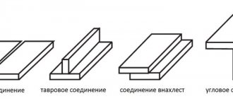
Features of each connection
Changing the polarity of the unit connection primarily affects the quality of the weld and the condition of the electrode. The use of reverse polarity when welding is characterized by the following positive features:
- increased amount of thermal energy consumed from the electrode;
- high-quality and deep penetration of the workpiece being processed;
- minimal splashing from the side of the fused product.
In turn, the direct current limits the flow of heat to the workpiece from the electrode side and reduces its melting compared to reverse polarity. However, the electrode rod still melts quickly and requires frequent replacement.
When evaluating each of these modes, it cannot be guaranteed that one is preferable to the other.
At first glance, reverse current welding has a clear advantage, but other factors of the welding process must also be taken into account.
For this purpose, for most electrodes used in welding, the recommended polarity is indicated on their packaging (on a special label).
Selecting modes for manual arc welding
SELECTION OF MANUAL ARC WELDING MODE
Arc welding is controlled by a number of parameters, namely: welding current, arc voltage, welding speed, type and polarity of the current, position of the seam in space, type of electrode and its diameter. Therefore, before starting work, you should select the values of these parameters so that the welding seam is of the required size and of good quality.
WELDING CURRENT (SELECTION OF WELDING CURRENT BY SELECTION OF ELECTRODE DIAMETER) The most important parameter when working with manual arc welding is the strength of the welding current. It is the welding current that will determine the quality of the weld and welding performance in general. Typically, recommendations for choosing the welding current are given in the user manual that comes with the welding machine. If there is no such instruction, then the strength of the welding current can be selected depending on the diameter of the electrode. Most electrode manufacturers place information about welding current values directly on the packaging of their products. The diameter of the electrode is selected depending on the thickness of the product being welded. However, remember that increasing the diameter of the electrode reduces the welding current density, which leads to wandering of the welding arc, its fluctuations and changes in length. As a result, the width of the weld seam increases and the depth of penetration decreases - that is, the quality of welding deteriorates. In addition, the level of welding current depends on the location of the weld in space. When welding seams in an overhead or vertical position, it is recommended that the diameter of the electrodes be at least 4 mm and the welding current reduced by 10-20%, relative to standard current values when working in a horizontal position.
After the welding current has been determined, the length of the welding arc should be calculated. The distance between the end of the electrode and the surface of the work being welded determines the length of the welding arc. Stable maintenance of the length of the welding arc is very important when welding, this greatly affects the quality of the welded seam. It is best to use a short arc, i.e. the length of which does not exceed the diameter of the electrode, but this is quite difficult to implement even with solid experience. Therefore, the optimal arc length is considered to be the size that is between the minimum value of a short arc and the maximum value (exceeds the electrode diameter by 1-2 mm)
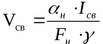
The choice of welding speed depends on the thickness of the product being welded and the thickness of the weld seam. The welding speed should be selected so that the weld pool is filled with liquid metal from the electrode and rises above the surface of the edges with a smooth transition to the base metal of the product without sagging or undercuts. It is advisable to maintain the advance speed so that the width of the weld seam is 1.5-2 times greater than the diameter of the electrode. If you move the electrode too slowly, a fairly large amount of liquid metal is formed along the joint, which spreads in front of the welding arc and prevents it from affecting the welded edges - that is, the result will be lack of penetration and a poorly formed seam. Unreasonably fast movement of the electrode can also cause lack of penetration due to insufficient heat in the working area. And this is fraught with deformation of the seams after cooling, up to cracks. The simplest method for selecting welding speed is based on approximately the average size of the weld pool. In most cases, the weld pool has the following dimensions: width 8–15 mm, depth up to 6 mm, length 10–30 mm. It is important to ensure that the weld pool is evenly filled with molten metal, because the penetration depth remains almost unchanged. The figure shows that as the speed increases, the width of the weld noticeably decreases, while the penetration depth remains almost unchanged. Obviously, the highest quality seams (in this example) are at speeds of 30 and 40 m/h.
TYPE AND POLARITY OF CURRENT
For most models of household machines for manual arc welding, a direct welding current is generated at the output by rectifying the alternating current. When using direct current, two options are possible for connecting the electrode and the part: With direct polarity, the part is connected to the “+” terminal, and the electrode to the “-” terminal. With reverse polarity, the part is connected to “-”, and the electrode to “+” At the positive pole more heat is generated than in negative mode. Therefore, reverse polarity when working with electrodes is used when welding thin sheet metal, so as not to burn it. You can use reverse polarity when welding high-alloy steels to avoid overheating, but with direct polarity it is better to weld massive parts
Direct polarity - Welding with deep penetration of the base metal Welding low- and medium-carbon and low-alloy steels with a thickness of 5 mm or more with electrodes with calcium fluoride coating: UONI-13/45, UONI-13/55, etc. Welding cast iron.
Reverse polarity - Welding with an increased melting rate of electrodes Welding low-alloy and low-carbon steels (type 16G2AF), medium- and high-alloy steels and alloys Welding thin-walled sheet structures
IGNITION (EXCITATION) OF THE WELDING ARC
Ignition (excitation) of the welding arc can be done in 2 ways. First method: We strike the end of the electrode on the surface of the metal (reminiscent of the movement of a lit match). This method is most often used on a new electrode. This method is simple and does not require any special professional skills. The second method can be called “touch”, because the electrode is brought vertically (perpendicularly) to the place where welding begins and, after lightly touching the surface of the product, the top is pulled back to a distance of approximately 3-5 mm. Most often, this method is used in hard-to-reach, narrow and other inconvenient places.