before—>
Welcome to the kuzov.info blog!
p, blockquote1,0,0,0,0—>
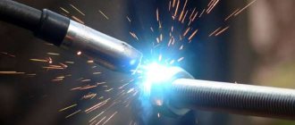
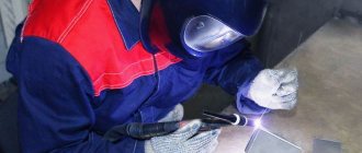
In this article we will look at how to set up a semi-automatic welding machine. Let's look at its adjustments, setting the shielding gas flow, and also see what welding seams are formed at different voltage settings. So, let's start with a brief definition of semi-automatic welding.
p, blockquote2,0,0,0,0—>
Semi-automatic welding is an electric arc welding in which the electrode is a welding wire fed to the welding site automatically through a torch. The gas protects the welding zone from oxygen and nitrogen in the air, which make the weld porous and brittle. It is also fed through the torch at the same time as the wire after the trigger on the torch is pressed. This type of welding is often called MIG/MAG welding (Metal Inert Gas/Metal Active Gas). The more correct technical name for this type of welding is GMAW (Gas Metal Arc Welding - electric arc welding in a shielding gas environment), and the slang name is “wire welding”, “semi-automatic welding”.
p, blockquote3,0,0,0,0—>
Semi-automatic welding, for all its simplicity, requires a lot of practice and learning the basics. It is important to properly set up the welding machine and properly prepare the metal for welding.
p, blockquote4,0,0,0,0—>
Here we will look at setting up the most affordable and widespread transformer-type semi-automatic welding machine.
- The process of welding with a semi-automatic welding machine without gas - with ordinary wire
p, blockquote5,0,0,0,0—>
Content:
p, blockquote6,0,1,0,0—>
Setting the shielding gas flow
h22,0,0,0,0—>
- The welding machine has an outlet for connecting to the cylinder. The shielding gas in the cylinder is under pressure. A gas reducer is installed on the cylinder. Here it is worth clarifying that there are different gearboxes, including those that are not intended for use in welding, since they do not have the required scale on the indicator showing the value for the gas entering the semi-automatic welding machine. On the correct reducer, the indicator, which when installed is located further from the cylinder, should have a scale showing gas flow (l/min for CO2 and a separate scale for Ar). Also, there are gearboxes with a rotameter, which shows the gas consumption per unit time by raising the float along a conical tube with a school. The indicator (pressure gauge), which is closer to the cylinder, shows the pressure in the cylinder (MPa or Bar). Since the cylinder contains liquefied gas, the gas pressure in the cylinder cannot always give a clear idea of its exact quantity. At different temperatures the pressure may be different. More accurately, the amount of gas in the cylinder can be determined by weight.
Reducer with indicators: A - gas pressure gauge in the cylinder, B - gas flow meter to the welding machine.
- The second indicator (flow meter) is used to adjust the air flow (shows the operating pressure that is supplied to the semiautomatic device).
- Also, there are two valves on the cylinder. One closes the cylinder, and the second, located on the reducer, regulates the flow of gas flowing to the burner when the cylinder is open. The valve on the cylinder is unscrewed counterclockwise and twisted clockwise as usual. The valve for adjusting the gas flow to the device, on the contrary, when tightened, increases the flow of protective gas, and when unscrewed, it decreases.
- When you open the main valve, you will see that the pressure will change from 0 to a certain value (cylinder pressure). Open it completely. Next, you need to slowly turn the adjusting screw on the gearbox until the arrow on the scale shows 7–10 l/m. If you do not have a flow meter, but a pressure gauge, then it should be 1–2 kg/cm2. This is the static pressure that will change when the burner trigger is pulled.
- To adjust the flow of shielding gas more accurately to the operating mode, turn off the wire feed so that when you press the torch trigger it is not consumed. You don’t have to turn off the wire, but press until the wire starts to move. In this position, adjust the air flow with the valve on the gearbox while looking at the indicator.
- In general, the shielding gas flow can be adjusted without indicators. You need to start welding with a minimum consumption of shielding gas. Next you need to look at the seam. If there is porosity, then you need to add gas until the pores no longer appear. Also, if welding takes place outdoors or in a ventilated room, then you need to take into account the influence of wind and drafts and add more gas supply. You can memorize the sound of air from the burner by ear at the correct settings for a specific metal thickness. There are no hard and fast rules when setting the shielding gas flow. It is necessary to adjust the gas to economical consumption, while ensuring that the quality of the seam is good.
Technological features of semi-automatic welding of thick metal
In order for welded metal structures to withstand loads, it is necessary to create reliable connections:
- seams must firmly connect all elements of the product;
- it is necessary to relieve the stresses that arise after welding inside the alloys . You can use preheating for this. After welding, it is recommended to ensure slow cooling;
- It is important to obtain a weld leg determined by technology ; this also strengthens the metal structure.
It should be taken into account that when working at high currents there is a risk of deformation, this means that the control dimensions of the part will change, and the shape of the structure will differ from that which was planned.
What gas should I use?
h23,0,0,0,0—>
The type of shielding gas affects the welding characteristics: penetration depth, electric arc and mechanical properties of the weld.
- Setting the parameters of a semi-automatic welding machine
p, blockquote8,0,0,0,0—>
- 100% carbon dioxide (most often used for welding steels) provides deeper penetration when welding, but increases the amount of spatter and the weld is rougher than with a mixture of argon and carbon dioxide.
- To weld stainless steel, a mixture of 98% argon and 2% carbon dioxide is used. For aluminum – 100% argon.
Aluminum welding
The use of shielding gases in semi-automatic welding makes it possible to perform high-quality connections of aluminum parts in this way. Welding aluminum is a rather complex process even for an experienced specialist; it will be even more difficult for novice welders to complete such work.
How to semi-automatically cook aluminum parts:
- the surface of the welded parts is cleaned from the oxide film;
- the workpieces are heated in a furnace or using a gas burner;
- the welding machine is switched on to high-frequency alternating current mode;
- a cylinder with argon or argon-helium mixture is connected;
- The arc is ignited and its length is maintained in the range of 12-15 mm.
In this way, parts made of this low-melting metal are welded. To perform the work, you will need to purchase aluminum products as filler wire. And to ensure stable wire feeding, the device must be equipped with a larger diameter nozzle.
Conclusion
For novice welders, you learned how to weld semi-automatically with carbon dioxide correctly from this article. To consolidate the information received, it is recommended to immediately begin practical exercises and carry out a trial connection of parts using this method. Video lessons will allow you to quickly master a semi-automatic machine at home.
It is recommended to start welding aluminum and other non-ferrous metals only after welding of ferrous metals is well mastered. This article tells you how to cook stainless steel with a semi-automatic machine.
Semi-automatic welding allows you to increase labor productivity and obtain a high-quality connection of metal parts of a structure or product. Learning to weld metals using machines is not so difficult if you know the operating principle of a particular semi-automatic machine, the nuances of selecting consumables, modes and technology for conducting the welding process. Semi-automatic power supplies are used in factories, workshops, service stations and at home when making connections with your own hands. During welder training in specialized institutions, lessons in obtaining the necessary skills are taught by experienced craftsmen, but you can also weld on your own using a semi-automatic welding machine, protecting the molten metal zone and without carbon dioxide. The main thing is to correctly set the welding current value and skillfully manipulate the torch.
Setting the voltage of the semi-automatic welding machine
h24,0,0,0,0—>
The semi-automatic machine has voltage regulators, and the current strength is constant and can vary depending on the wire feed speed and its extension.
- Semi-automatic welding machines use voltage to generate the heat needed for welding.
- The voltage is adjusted on the device using regulators. This is a step adjustment. The photograph, as an example, shows a device with two switches: one allows you to set two welding modes, and the other regulates the voltage within these modes (min/max). The result is four voltage settings that must be selected depending on the thickness of the metal and the diameter of the welding wire.
- On some semi-automatic welding machines, there is a table on the inside of the cover showing what voltage and wire speed to use, depending on the thickness of the metal and the diameter of the welding wire. There are many such tables on the Internet. But this data is individual for each machine and is a good starting point for setting the correct parameters for welding, they need to be adjusted according to the situation. You need to try, experiment on a specific metal and find the optimal settings.
[adsp-pro‑3]
p, blockquote9,0,0,0,0—>
Defects that occur when welding massive parts. How to avoid problems
During work, problems may arise that affect the quality of connections.
| Description of the defect | Causes and remedies |
| Pores appear during welding |
|
| The seam is too convex | It is necessary to configure the semi-automatic machine correctly. Adjust wire feed speed and current value. Test on unnecessary scraps of metal. The wire should flow smoothly into the welding zone and melt in a timely manner without cracking or clicking. |
| Spattering of metal during welding |
|
If a metal structure has a complex shape and there is concern that it will deform during welding, assemblers often grab additional temporary reinforcements from corners, channels or reinforcement in critical places. They allow you to keep the dimensions of the product within specified limits. When the part has cooled, they can be cut off.
Welding massive parts with a semi-automatic machine is considered the most productive method. With a minimum of effort you can get beautiful and reliable connections.
Features of welding thin metal, and how to weld a burn
Setting the wire feed speed
h25,0,0,0,0—>
- The wire feed speed must be adjusted each time the voltage is changed or the wire is changed to a wire with a different diameter. Expensive welding machines may have automatic wire feed speed adjustment. In them, the speed increases automatically as the voltage increases.
- First adjust the voltage, and then adjust the wire feed speed to it. That is, the wire feed speed must be adjusted to the speed at which it will melt.
p, blockquote10,0,0,0,0—>
- The wire feed speed controller also serves another purpose - it regulates the current. Voltage and current are related and, to some extent, are based on the size of the wire and its speed. In a semi-automatic machine, the set voltage remains unchanged, but the current varies slightly depending on the wire feed speed and the electrode (wire) stick out. Thus, the faster the wire is fed to the welding site, the greater the current strength and the higher the welding temperature, but for a specific, established type of voltage this is only a small range of changes in current strength.
- The wire outside the welding process (without an electric arc) moves faster. When an arc is formed, the speed of the wire decreases.
The metal must be prepared for welding
Before cooking, be sure to clean the metal.
Before cooking, the metal is cleaned of various contaminants, rust, dyes, coatings and lubricants.
Then the parts that will be welded must be aligned with each other without any gaps. The parts can be aligned using clamps or bolts.
Then select the value of the welding current. It depends on the thickness of the metal. If a metal of small thickness is being welded, the current strength is approximately 50 A. In order to set the current strength, you must first read the instructions for the device. If the current strength is chosen correctly, the weld will be of high quality.
Then a test brew is performed. Perform weld spots on metal. Welding is performed wearing a protective helmet and gloves. First, bring the device to the surface at a distance of 4 mm. The device must be held with both hands by the handle. The button is pressed and the arc lights up. After 3 seconds the button is released. The result was a welded point. You need to evaluate its quality.
If the welding current is too low, the molten metal does not flow properly and the part is not fully welded. With this option, you need to increase the current and boil again. If the current is chosen correctly, the molten metal flows well and welding is performed efficiently. A drop of molten metal forms on the opposite side of the part.
If the current is too high, the weld point sags and a drop will hang on the back side of the part. If the current is so high that a hole is burned in the metal during welding, then it is necessary to reduce the current. Test welding is carried out until the correct weld point is obtained. After trial welding, you can learn to weld pieces of metal.
Polarity when welding semi-automatically
h26,0,0,0,0—>
Before welding, you need to decide which polarity you will use.
- Carbon dioxide pressure reducer. Adjusting the shielding gas supply
p, blockquote11,0,0,0,0—>
Plain copper-clad wire that is used with shielding gas should be used with reverse polarity when positive is applied to the wire. Straight polarity is used when the semi-automatic machine has flux wire installed, which is used without gas. In this case, a minus is applied to the wire, and a plus is applied to the metal being welded through the terminal. Thus, maximum heat generation is generated on the wire. This is necessary so that the flux in it can work properly.
p, blockquote12,0,0,0,0—>
If you use the wrong polarity for a certain electrode (in the case of a semi-automatic wire), then the strength of the weld will be poor. If the wrong polarity is used, there will be a lot of spatter, poor welding penetration and the welding arc will be difficult to control.
p, blockquote13,1,0,0,0—>
To change the polarity, you need to open the cover of the semiautomatic device and swap the terminals. Next to the terminals there is a table specifying the order of the terminals.
p, blockquote14,0,0,0,0—>
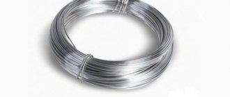
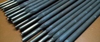
Welding wire
p, blockquote15,0,0,0,0—>
The semi-automatic machine can use two types of wires: plain copper-coated wire and flux-coated wire.
p, blockquote16,0,0,0,0—>
- Simple wire for semi-automatic welding is used with shielding gas and does not have any additives that can “resist” corrosion and contamination. Therefore, the surface must be prepared carefully.
- The second type of wire has a flux in the center, which, when burned, forms a protective gas. Thus, you can do without a gas cylinder. This wire creates deeper penetration when welding than conventional wire with gas. Flux-cored wire creates a lot of spatter and slag in the welding area, which must be cleaned up after welding is complete. When welding with such wire, minimal surface preparation is required, minor contamination is forgiven. This wire also works well when it's windy outside. For flux-cored welding, the machine must be set to straight polarity (see above).
- The greater the thickness of the metal being welded, the larger the diameter of the wire you need to use, since larger diameter wire conducts more electricity and gives more heat and better penetration.
Features of flux-cored wire welding
If shielding gas is required when working with copper-plated wire, then the use of powdered wire does not require it. The process is reminiscent of electrode welding - with the formation of a slag crust that must be removed. The wire coating contains elements (flux) that, when heated, protect the weld pool from exposure to air. Distinctive features:
- high mobility - no need to move cylinders around the work site;
- Many varieties of wire grades allow you to choose the one that is needed in specific conditions;
- flux-cored wire is often used during outdoor work ; in this case, gusts of wind do not interfere with the process, unlike welding with gas.
The main disadvantage is the high cost. On average, flux-cored wire is 50% more expensive than regular copper-plated wire.
Wire overhang
h27,0,0,0,0—>
Wire stickout is the distance between the end of the tip and the end of the wire. When using carbon dioxide or mixtures, keep the overhang between 0.6 mm and 1 cm. Too much overhang will weaken the arch. The smaller the wire stickout, the more stable the electric arc and the better penetration will be obtained even with low voltage. Thus, the best wire overhang is as short as possible. However, wire protrusion may depend on how far the torch tip is recessed into the gas nozzle. The further the tip is recessed into the nozzle, the longer the wire extension should be.
p, blockquote17,0,0,0,0—>
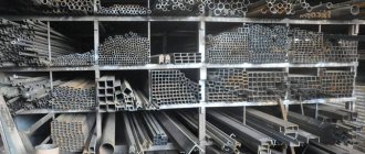
Necessary equipment and materials
To work you will need:
- Powerful welding machine . The maximum value of welding current is not less than 250 A.
- Cylinder for storing and transporting carbon dioxide . There are containers with a volume of 5, 10 and 40 liters. The cylinders are painted black.
- Reducer for reducing gas pressure . A special CO2 device is required. It is desirable to have a heating element.
- Hose and clamps - for connecting the cylinder.
For semi-automatic welding of steels, use wire type Sv-08G2s or similar for welding carbon steels 08x18n9t, as well as an equivalent for welding corrosion-resistant steels. Diameter – 1 to 1.6 mm. Common reels weigh 5, 15 and 18 kg.
Approximate cost of wire for welding carbon steels on Yandex.market
Some devices operating on a 220-volt network can only accommodate small coils of wire.
Position of the torch tip relative to the nozzle
h28,0,0,0,0—>
The tip of the welding torch can be recessed into the nozzle, stick out slightly from the nozzle, or be flush with the nozzle. Most often when welding sheet metal with gas shielding, the tip of the nozzle should be flush with the edge of the nozzle opening. When spot welding, the torch tip must be recessed.
- The distance between the tip of the contact tip and the edge of the nozzle may vary. Nozzles and tips come in different sizes and can be positioned differently relative to each other. Depending on the design of the welding torch, the nozzle can be rigidly installed, or it can be adjusted and installed differently, making the tip recessed inside the nozzle, flush with the nozzle, or protruding from the nozzle.
- Typically, when welding sheet steel with shielding gas (carbon dioxide or mixtures), the tip of the torch tip should be flush with the edge of the nozzle hole.
- When using flux-coated wire (which requires more heat to activate the flux), you must maintain a longer wire extension. Therefore, so that the distance of the nozzle from the welding zone is not too large, the tip must be recessed inside the nozzle. The tip should be slightly recessed even when welding with high voltage, when the wire stickout should be greater. Also, the torch tip can be recessed if you need to weld in spots and short stitches, when the nozzle can rest against the metal being welded.
- Using the wrong tip or nozzle can cause excessive spatter, burn-through, warping, and lack of penetration.
What and by what methods can be welded semi-automatically
Most often, semi-automatic welding is used for welding sheet metal - stainless steel, aluminum, non-ferrous metals. Products made of cast iron can also be welded. Knowing how to properly weld ferrous metals, you can begin welding non-ferrous ones.
Without the use of a semi-automatic machine when joining thin metals, it is difficult to imagine service station services, assembly and repair of household appliances, installation of all kinds of fences, containers for collecting and heating water in the country, etc. In industrial conditions (for example, in the automotive industry), semi-automatic welding is used when it is necessary to obtain high quality welds.
You can semi-automatically weld a car or replace sections of damaged parts using the butt welding method, but it requires some welding experience. The connection along the prepared holes should be made where the pre-cut patch is installed. Overlap welding, which involves point-to-point joining of surfaces, is accessible even to beginners.
Getting started with a semi-automatic welding machine
h29,0,0,0,0—>
To start working, the semi-automatic welding machine must be completely ready for the welding process. The wire must be installed and the gas cylinder connected. It is necessary to install a ground clamp on the metal being welded. It must be installed at a distance of 15 to 50 cm from the welding zone. The metal must be free of rust, paint, oils and dirt. Any slight resistance will affect the welding process. Dirty metal during welding will cause spatter and burn through, as well as fire.
p, blockquote18,0,0,0,0—>
[adsp-pro‑2]
p, blockquote19,0,0,1,0—>
Correctly adjusted voltage and wire feed speed should result in good welding flow. The correct settings will produce the characteristic hissing-buzzing sound that all welders know well. More details about the welding process can be found in the article “MIG/MAG semi-automatic welding technology”.
p, blockquote20,0,0,0,0—>
Wire welding
This type of semi-automatic connection of parts is carried out using flux-cored wire, which has a special charge in its design. It is also called self-protective, because it protects the metal of the molten seam during the process of joining parts from harmful components in the air. You can cook semi-automatically without gas when performing installation and construction work at the location. Used in garages for car body repairs and other household work involving joining or fusing. You can cook metal blanks with a thickness of 0.5÷10 mm.
The general view of the semi-automatic machine for welding with flux-cored wire and the appearance of a high-quality connection are shown in Fig. 2:
Typical problems are listed in the table:
| Type of malfunction | Cause or causes | Remedy or remedies |
| Unable to strike arc | There is no contact in the circuit | It is necessary to check: - contacts (clean them and tighten them); - end of the wire (clean off the flux crust - knock it down or bite off a small piece with wire cutters) |
| The arc breaks during the connection process | Large welding current | Decrease |
| Wire feed speed is low | Increase | |
| The electrode wire does not enter the channel | There is no contact in the start button | Clear |
| Fuses blown | Exchange for new ones | |
| Phase loss in the motor circuit | Eliminate the break by disconnecting control from the network | |
| The wire sticks to the metal of the parts being welded | Current strength is low | Increase |
| Wire feed speed too high | Decrease | |
| Wire feeds jerkily or at inconsistent speed | Weak clamping by upper pressure rollers | Change spring force |
| Wear on the surface of the drive rollers | Replace with new ones | |
| Sticking in the tip of the welding head | Clean or replace if worn or burned. | |
| Welding cable bends | Align | |
| Feed rollers wear out quickly | High pressure roller pressure | Let loose |
| Torch body energized | The insulation between the contact tip and the burner body is broken | Restore isolation |
| There is a foreign metal object between the body and the tip | Delete | |
| Pores appear in the weld when welding in shielding gases | Gas protection broken | Check: - gas quality; — arc voltage; — correspondence of the wire grade to the metal to be connected |
| Gas does not enter the cooking zone | Problems with the hose cable (pinched or broken) | Eliminate the cause |
| The gas cut-off device did not work | Check the power supply to the electromagnet coil | |
| The gearbox hole is clogged | The gearbox needs to be warmed up | |
| The nozzle outlet is blocked by metal splashes | Remove splashes or replace nozzle | |
| Flux does not enter the welding torch | Compressed air pressure is low | Increase |
| The injector or flux tube is clogged | Clean and dry the flux if necessary. |
Examples of welds with different voltage settings
h210,0,0,0,0—>
The voltage determines the height and width of the weld.
p, blockquote21,0,0,0,0—>
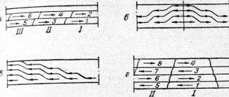
The photo shows welds on 1.2 mm thick sheet metal made with increasing stress (from left to right). Seams made on low settings turned out narrow and tall, while on high settings they turned out wide and flat.
p, blockquote22,0,0,0,0—>
The photo on the left shows seams on sheet metal made under increasing stress.
From left to right from lower voltage to higher voltage. In the second photo, the reverse side of the sheet shows penetration (penetration). If you look from the reverse side, the two seams on the left did not have good penetration (welding) along the entire length. The three seams on the right have good penetration along the entire length.
p, blockquote23,0,0,0,0—>
Welding seams in section p, blockquote24,0,0,0,0—
Recommendations for semi-automatic welding of ceiling seams
By changing the settings of semi-automatic welding equipment, you can achieve different types of seams.
Depending on the appearance, welded joints are divided into:
- T-bars;
- butt;
- corner;
- overlapped
Possible welding problems
h211,0,0,0,0—>
- The wire is welded to the metal without forming an arc. Cause: Wire feed speed is too high for the set voltage.
- When spatter (small balls of metal) fly out during welding. Brown and green colors on the seam and porosity also appear. Reason: there is no gas or not enough shielding gas is supplied from the torch to the welding zone.
- The seam does not penetrate deep enough. Such a seam will not be strong. You need to add voltage and increase the wire feed speed.
- Burning metal. This happens if the voltage is too high for a given thickness of metal.
- Poor penetration, haphazard seam, jerky welding. It may seem as if there is not enough voltage or wire feed speed. Check the ground clamp and the cleanliness of the metal it is clamped to.
- The burner “spits” and does not produce a continuous seam. This can happen if the torch is too far from the welding site. You need to keep the torch tip about 0.6 - 1.2 cm from the welding area.
- The wire rarely (occasionally) touches the metal, but once contact occurs, the wire melts and the residue remains at the tip of the tip. Cause: Wire feed speed too slow.
[adsp-pro‑4]
p, blockquote25,0,0,0,0—> p, blockquote26,0,0,0,1—>
Print article
h31,0,0,0,0—>after—>
The saturation of home workshops with complex professional-level power tools is impressive. But not all of the equipment's rated capabilities are used. How to set up a semi-automatic welding machine for metal of different sections, change it to aluminum, stainless steel - dry information in the instructions is not enough. Let's turn to the knowledge of production workers.
Pros and cons of semi-automatic metal welding
Semi-automatic welding has a number of advantages:
- Suitable for beginner welders.
- There is no need to constantly remove slag from the weld area.
- There is no need to constantly change electrodes.
- Metal does not splash during operation.
The disadvantages include:
- It is impossible to use the device in windy conditions: protective gases will blow out from under the burner.
- The gas cylinder makes the design of the device somewhat cumbersome.
External influence on settings
Changing the spatial position of the seam, strengthening the leg, thickness, and configuration of the joints of one metal will require different settings. Basic settings of a semi-automatic machine (PA):
- Arc voltage; the adjustment is reflected in the change in current value.
- Current – wire feed; An increase in wire feed speed is responded to by a proportional increase in the current value and vice versa.
- Gas consumption is set based on the main parameters and is regulated by assessing the quality of the seam while excluding pore formation.
The initial setting of welding parameters is carried out using averaged table values.
Further, based on the results of the test pass, the modes of electric arc welding in a shielding gas environment are adjusted.
For an experienced practitioner, even the sound of a lit arc is informative. Once you purchase a semi-automatic machine, you will have to get used to its features and the need to adjust to changes:
- The configuration and assembly of PAs with equivalent characteristics differ in their filling; differences in configuration are found among the same manufacturer.
- Voltage fluctuations disrupt settings; the transformer PA will turn off, and the inverter may burn out.
- Changing the composition of the shielding gas.
- Changing the brand and diameter of the wire.
- Even minor repairs or replacement of components will have an impact.
Gas protection
Gas flow also refers to calculated tabular values . Does not directly affect the settings of the semi-automatic welding machine. Control is simplified if the gearbox is equipped with 2 scales. Registration of the reduced flow value is perceived more objectively with the installation of a rotameter.
The rotametric flow meter shows the supply of carbon dioxide (argon) working pressure in constant values. The static pressure reading will drop when the burner trigger is triggered, creating a protective cloud. The initial range for the rotameter is 6–10 l/min, for a gearbox with pressure gauges – 1–2 atm.
Economical consumption is selected according to the porosity of the seam: the gas flow increases until the pores disappear . In a room with forced exhaust and in the wind, in order to save money, it is preferable to use cored self-protecting wire.
Selection of gas mixture
The choice of mixture is determined by the quality requirements and material properties:
- CO2 is an ideal protection for the weld pool of structural steels, deep penetration, but the spattering and roughness of the weld are not suitable for fine work.
- A mixture of argon and carbon dioxide C25 (75% Ar; 25% CO2) - the combination is suitable for welding thin-sheet structures, creating a uniform seam with a minimum of splashes.
- Composition of 98% Ar; 2% CO2 – for stainless steels.
- For aluminum – argon in its pure form.
Voltage setting
The power consumption for burning the arc and melting the metal is determined by the voltage setting. Energy consumption increases with increasing penetration depth (material thickness) and wire diameter.
The settings of household PAs are stepped. Coarsening with min/max modes or multi-mode, with soft adjustment as an extended range of adjustment of the welding voltage of the Wester MIG-110i semi-automatic machine for 10 settings.
On the inside of the casing cover there is a table of regulations for voltage settings . This is the manufacturer’s main hint; it is printed on models that differ in power and technical equipment.
The final solution is how to set up a semi-automatic welding machine for the operator. Vague recommendations are not dogma, the main criterion is the depth of penetration and the strength of the connection.
Wire feed speed
The wire feed speed controller controls the current intensity . The feed amount is one of the main variable characteristics. Set after voltage selection: the melting speed determines the movement of the electrode in the burner.
This value is subject to adjustment after changing the brand and diameter of the wire, changing the voltage. There are PAs with automatic mode adjustment, but they are in the segment of expensive equipment.
Fine-tuning the movement of consumables to optimize adjustments is desirable . Excessive acceleration will lead to sagging, deceleration will lead to subsidence, waviness, and seam breaks. The balance of current and voltage, controlled by the feed rate, adds up to an optimal roller.
The first indicator of a mode discrepancy is revealed in action - the feed speed with the ignited arc decreases, but the wire does not have time to melt, bends, sticks to the workpiece, and active spatter occurs.
Insufficient supply - the inverter electrode burns out before touching, the tip becomes clogged. Selecting the speed/current mode for the set voltage is the first step towards professionalism .
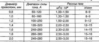
Wire feed speeds in a semi-automatic machine, a table of the direct relationship of the effect of changing settings on the final result:
Polarity
The procedure for changing polarity is simple. Under the cover there is a sign indicating which type of metal and wire require direct or reverse polarity. Direct - the burner is connected to the minus terminal.
With straight polarity, the melting of the wire is accelerated by 50%, but the stability of the arc decreases. Welding with self-shielding flux-cored wire is carried out with straight polarity .
The maximum heat generation energy is spent on protecting the seam. The flux will react without any residue. The tendency to splash is compensated by indifference to under-cleaning of work areas and gusts of wind. Costs in the form of splashes and slag crusts are a necessary evil. A solid copper plate in a gas cloud is connected to the positive terminal . Preparing material for welding involves cleaning up signs of corrosion, contamination of joints, and cutting. Conductivity increases with increasing diameter. For large cross-section workpieces, there is a reason to increase the wire cross-section.
Inattention to such “trifles” leads to a drop in quality: excess splashes, reduced weld pool depth (lack of penetration). Control and quality control of arc combustion will become significantly more difficult.
Wire ejection and release
The length of the consumable electrode extending from the contact tube (tip) and the size of the working gap of the torch affect the quality of the permanent connection.
Important! Warping, lack of penetration, burning of excess spray are the reasons for the disproportion between the diameter of the wire and the size of the exit from the nozzle.
The relative position of the burner tip relative to the nozzle varies in individual designs. They are located at the same level, the contact tube is recessed or extended relative to the nozzle up to 3.2 mm.
At a short reach, welding of structural low-alloy steels is carried out - increasing the distance thins the cover with protective gas. The flux-cored wire is artificially lengthened to increase the melting point .
Arc setting
Already simple PA models have a vernier control over inductance values . Setting the hardness changes the temperature of the arc and the depth of penetration with a noticeable convexity of the seam. Parts are sensitive to overheating and thin walls no longer interfere with welding.
Reducing the compression of the current channel (increasing inductance) raises the melting temperature, the penetration is deep, and the weld pool liquefies. The seam bead is flattened. Controlling the penetration depth, arc and bath temperature is a qualitatively new level of setting up a semi-automatic welding machine.
Small diameters of the additive make the arc more stable, the deposition rate increases, the penetration depth is optimized, and spatter is reduced. Based on the convexity of the seam and the amount of spattering, the length of the arc is specified: a short one gives a volumetric seam, a long one interferes with the concentration of the melt .
| Inductance max | Inductance min |
| The penetration deepens | Low temperature arc |
| Weld pool liquefaction | Splashing increased |
| The seam bead is even and smooth | Volumetric seam bead |
| Corner, reinforced seams | Setting up a semi-automatic machine for welding thin metal |
Wire feed speed control
The wire feed activation switch can be two-position (High/Low) or multi-stage. Larger diameter solder is dispensed at a slower rate, optimizing the process.
Before starting work
When the PA is prepared for work according to the instructions, it is worth spending time clarifying the configuration modes. To help, we offer a table as a guide. Drawing up an analogue with the individual properties of PA will help in determining the best modes and clarifying the capabilities of the technique .
The own table of welding current for a semi-automatic machine tends to grow with new material and welding conditions. It won't hurt to check the position of the switch on paper to help you remember.
The recommended voltage is selected. By manipulating the current strength and the additive supply rate, we select the optimum with a decrease in current and a maximum supply. Then, as the amperage increases. The voltage changes every 0.5 A. The detailed table will become your personal speed adjustment instructions .
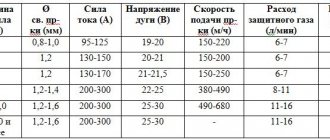
Indicative table: welding current (wire feed speed), interdependence of process components:
The influence of stress on the quality of the seam
A convex weld with sufficient penetration without porosity, sagging and undercuts will only be produced when the main component - stress - is balanced with the accompanying ones.
Low settings produce a tapered high seam with little penetration. High – flattened with spreading and deep crater of the bath. Excessive voltage has a negative effect on weld formation : it is not possible to create a bead of sufficient volume when the melt depth is on the verge of burning through.
In the photo above:
- the calorific value of the voltage is optimal;
- insufficient;
- redundant.
Possible problems and errors
Problems and mistakes when blindly following average recommendations are the fault of the welder. This was mentioned above. Selecting a welding mode is a delicate matter. Creativity and attention to detail are half the way to success .
Relying on the experience of a professional will help:
- Crackling or clicking sounds are a signal of insufficient solder supply speed.
- The additive melts further away, up to the tip - the feed rate is reduced.
- Excessive spatter - increase gas supply and inductance.
- Porosity, shades of brown and green on the seam – poor gas protection.
- Burning, lack of fusion - too much or too little voltage, adjust the inductance.
- Unevenness of the seam, instability of the arc, lack of penetration - contamination of the welding field, loose clamp of the mass.
- Variability of the fullness of the bead, notches - the speed of the torch and the position relative to the seam are disturbed.
- The seam is interrupted, uncontrolled spattering - the arc length has been exceeded.
The semi-automatic welding machine is a very convenient device for working at home and in small workshops. You can work with it in any conditions, no special preparation of the workplace is required, it is compact almost like a regular inverter.
Unlike manual arc welding, it does not require a highly qualified welder to work with it. Correct setting of a semi-automatic welding machine allows even a low-skilled welder to perform high-quality work.
Depending on the type of material being welded and its thickness, it is necessary to correctly set the wire feed speed and shielding gas. Next, the welder needs to move the torch evenly along the seam, and a high-quality weld will be obtained. The whole difficulty lies in the correct selection of welding parameters for a specific material.
Types of sutures and methods of applying them
According to the position and type of connection, seams are divided into several types, which determine the welding settings.
According to their position in space they are divided into:
They can be overlapped, end-to-end, and there are also T-joints and corner joints. There are several methods for placing seams when welding thick metal.
Overlay methods
The method of welding thick metal in a cascade is as follows: the entire section is divided into 20 cm sections. First, the lowest section, called the root section, is welded.
Its length is approximately 20 cm. A new layer is made over the root overlap, without interrupting the arc. Its total length will be 20 +20 = 40 cm. The welding method is best understood in the diagram. It is applied to thick metals when the sheet thickness is more than 20mm. With this welding method, layers are applied to uncooled metal, which reduces deformations and internal stresses.
Welding thick metal with a slide is similar to a cascade, only two welders work from the middle to the edges of the seam.
They cascade along the length and width. The goal is to ensure that the contact area is hot when applying the next layer.
Length
Seams are divided into short ones up to 25 cm long, medium ones up to 1 m, and long ones over 1 m. Short ones are laid in one pass.
When welding thick metal, it is necessary to make several layers - one for each pass, since each subsequent layer becomes wider, the welder makes zigzag or spiral movements across the seam. Thus, the edges of the welded parts are melted.
This technology is usually used for butt joints of thick metal. Medium and long sutures are applied using the cascade and slide methods.
When welding corner and T-joints, a multi-layer, multi-pass double-sided weld is used. First, the root seam is formed. Then a second layer is laid on top of it with an offset to one of the joints, then a third with an offset to the second joint with its melting.
The fourth goes on top of the second layer, melting the edge of the part. The fifth passes next to the fourth, and the sixth layer on top of the third, melting the edge of the second part. The seventh layer is applied on top of the fourth, fifth and sixth layers.
On the back side of the seam, the eighth finishing layer is applied to the first layer and the edges of the product.
Welding machine parameters
Reducing the welding current reduces the depth of the weld pool and vice versa.
Its width practically does not change. The required current depends on the thickness of the metal and the diameter of the welding electrode. An increase in voltage leads to an increase in the width of the seam, while the penetration depth decreases. The penetration depth depends on the speed of movement of the electrode, all other things being equal. It increases at speeds up to 40 m/hour, and then decreases. The seam width decreases continuously with increasing speed.
Working with thick metal requires more training for the welder. The seam always turns out to be multi-layered. Before taking on such welding, it is necessary to master the basic technological techniques.
Equipment capabilities
To properly configure a semi-automatic welding machine, an understanding of the welding characteristics is required; it is also necessary to understand the features of the semi-automatic machine.
Semi-automatic welding machines allow you to work with almost any metals and their alloys. They can weld non-ferrous and ferrous metals, low-carbon and alloy steel, aluminum and coated materials, are capable of welding thin metals up to 0.5 mm thick, and can even weld galvanized steel without damaging the coating.
This is achieved due to the fact that flux, flux-cored wire or shielding gas, as well as welding wire can be supplied to the welding area, and the supply occurs automatically, everything else is done as in manual arc welding.
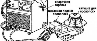
Semi-automatic welding machines are produced in different classes, but they all consist of:
- control unit;
- power supply;
- welding wire feed mechanism with reel;
- welding torch;
- power cables.
In addition, there must be a cylinder with a reducer and inert gas (carbon dioxide, argon or mixtures thereof), and a funnel for flux.
The wire feed mechanism consists of an electric motor, a gearbox and feed or pull rollers.
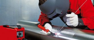
Welding with a carbon dioxide machine
Semi-automatic welding in a carbon dioxide environment is carried out during the assembly and repair of cars.
Carbon dioxide welding diagram.
Advantages of cooking in carbon dioxide:
- The ability to make a small narrow seam allows you to weld small parts to the metal surfaces of the machine.
- When cooking, a small narrow layer of paint is damaged, which reduces finishing work in the future.
- High electrode feed speed, which increases labor productivity.
- The welding seam is very durable and of high quality.
- There is no need to pre-fit the parts that will be welded.
- Welding in carbon dioxide allows you to obtain welded joints of various thicknesses.
- Of all the shielding gases used in welding, carbon dioxide is the most readily available.
- Performing work when welding in carbon dioxide is quickly mastered by the welder.
Recommendations in the instructions
Before starting work, it is necessary to reliably ground the welding machine and only then begin setting up.
The semi-automatic welding machine must be connected to a gas cylinder system with protective gas. It is necessary to check the presence of welding wire in the spool, if you need to reload it and stretch it to the torch handle. The gas supply speed is of great importance in the welding process.
Therefore, it also needs to be installed. Gas equipment has gearboxes indicating gas consumption in liters. This is very convenient; you just need to set the required flow rate within 6-16 liters.
The operating instructions for the device provide recommendations on how to properly set up a semi-automatic welding machine, what current to use to weld a specific metal, and at what speed to feed the wire.
The instructions should contain special tables in which everything is described. If you set all the parameters in accordance with them, then everything should work out.
In practice there may be difficulties. The quality of semi-automatic welding is influenced by many parameters. If the supply network does not meet the standards, then the power source will produce voltage and current that is not what is needed, the parameters will be unstable.
The temperature of the medium, the thickness of the metal, its type, the condition of the surfaces being welded, the type of seam, the diameter of the wire, the volume of gas supply and many other factors affect the quality of semi-automatic welding.
Tables of recommended welding conditions are given for certain conditions, which cannot always be achieved. Therefore, when welding semi-automatically, many adjustments are made experimentally.
Of course, the recommended values are initially set, then the welding parameters are fine-tuned.
How to weld thick metal using a semi-automatic machine
Having previously found out how thick the metal is to be welded, you can prepare it for this process according to all the rules. To weld thick metal - parts with a wall thickness of more than 4 mm - you need to chamfer the intended joints. Please note that this can be done using gas cutting, but hand and pneumatic chisels are also used. Metal sheets with a thickness of 5 - 15 mm are equipped with V-shaped bevels; for parts with a thickness of more than 15 mm, an X-shaped bevel is assumed.
semi-automatically welded thick metal
The seam when connecting thick surfaces, especially with T-joints, must be strengthened with the help of two more, located on its upper and lower edges. The arc must not be drawn along a straight line, but must be made in zigzag or reciprocating movements. The weld metal should extend onto the surface of the product to a width equal to the thickness of this part. To obtain a reliable connection, cascade or slide welding is most often used.
When welding thick metal, there is a high probability that the anti-corrosion coating of the part will be damaged. Therefore, after welding, the part must be treated with special compounds. If it is made of low-alloy steel, then preheating will not hurt. Heat treatment will soften the product, preparing it for further work.
How to weld thick metal while maintaining the original qualities of the part? To reduce deformation or completely prevent it, thick metal products are securely fixed using clamps before welding. This can be done on a workbench, assembly table or steel plate.
Setting current and wire feed speed
First of all, the strength of the welding current is set, which depends on the type of material being welded and the thickness of the workpieces.
This can be found out from the instructions for the semi-automatic machine or found in the relevant literature. Then the wire feed speed is set. It can be adjusted stepwise or smoothly. With stepwise adjustment, it is not always possible to select the optimal operating mode. If you have the opportunity to choose a device, buy a semi-automatic welding machine with continuously adjustable wire feed speed .
The control unit must have a forward/reverse wire feed mode switch. When all the settings have been made in accordance with the operating instructions for the semi-automatic machine, you need to try working on a draft sample with the same parameters. This must be done because the recommendations are average, and in each individual case the conditions are unique.
At a high wire feed speed, the electrode simply will not have time to melt, there will be large deposits or shifts on top, and at a low speed it will burn out without melting the metal being welded, the weld bead will sag, and depressions or breaks will appear.
How to weld thin metal using semi-automatic welding
Knowing how to properly weld thin metals, you can use welding with a semi-automatic inverter when repairing cars, making small-diameter pipes, water tanks, etc. The thickness of the welded metal is in the range of 0.2-4 millimeters. First of all, you need to choose the correct thickness of the electrodes, since electrodes with a thickness of more than 4 mm will extinguish the welding arc. So that it burns continuously, metal up to 1 mm is welded with electrodes of 0.5 - 2 mm. With a part thickness of 1.5 - 2 mm, the electrode will have a diameter of 2 - 2.5 mm. Professionals recommend semi-automatic cooking with 2-3 mm electrodes.
welding seam obtained using a semi-automatic machine
Welding metal 1 mm thick and thinner is a rather difficult task, since there is a high probability of burning through the seam. To avoid defects, you need to join the metal by electric welding using tacks. The distance between them should be 1.5 - 2 cm. Then short seams are made. After each of them, you need to take a short pause so that the metal has time to cool. A long weld joint can be obtained by welding metal surfaces alternately. In addition, to cool the parts, a copper or brass sheet located directly behind them is used, as well as ordinary moistened textiles, which are used to wipe the surface between the seams.
How to weld metal correctly if you are new to welding? The semi-automatic machine greatly simplifies the work, but some nuances should still be taken into account:
- it is necessary to select the correct welding mode.
- The connection of surfaces occurs at low currents (10-75 A).
- The wire feed speed is much lower than when welding thick metals.
- The movements of the torch must be uniform, otherwise the welding bead will overflow or the part will burn through.
- When spot welding, connections begin from the center of the workpiece, located below. This avoids metal filling the hole.
- By cleaning the surfaces from rust, dirt, traces of paint and degreasing them, you will not only get a more durable seam, but also avoid toxic fumes. When cleaning, do not remove a large layer of metal.
- The angle between the torch and the welding area should be 45 degrees.
- To obtain complete penetration, it is recommended to weld with a gap.
- The filler wire must have a long melting period.
- Be sure to wear protective clothing.
- First read the recommendations of experienced welders on how to weld thin metal.
You can read about labor protection during welding here.
semi-automatic spot weld
Thin metal can be welded semi-automatically in horizontal, vertical, ceiling, and lower positions. The latter method is very popular. Many novice welders wonder how to weld thin metal in a vertical position? To obtain a vertical seam, take into account the thickness of the metal being welded:
- Up to 3 mm. Semi-automatic cooking is done from top to bottom.
- More than 3 mm. Welding is carried out in the direction from bottom to top.
Adjusting parameters
Adjustment of current or voltage depends on the thickness of the workpieces. The thicker the product being welded, the greater the welding current. In simple semi-automatic welding devices, the current adjustment is combined with the wire feed speed.
In professional semi-automatic machines, the adjustments are separate. The correct setting can only be determined experimentally by making an experimental seam on a test piece. The roller should be of normal shape, the arc should be stable, without splashes.
Some semi-automatic models have inductance adjustment (arc settings). With low inductance, the arc temperature drops, the depth of metal penetration decreases, and the seam becomes convex.
This is used when welding thin metals and alloys that are sensitive to overheating. With high inductance, the melting temperature rises, the weld pool becomes more liquid and deeper. The seam bead becomes flat. Welding in this mode is used for thick workpieces.
The welding wire feed speed switch in models capable of working with different diameters requires additional adjustment taking into account the specific thickness of the wire.
Even after fully studying the manufacturer’s recommendations, it is not always possible to obtain the desired operating mode of the semi-automatic machine.
Having set the optimal settings for welding a workpiece today, it may turn out that the next day they will become suboptimal because the quality of the network has changed or the position of the product on the workbench has changed.
That is, setting the modes is a constant and individual process because it also depends on the work style of the welder himself.
Welding process
Thick pieces should not be cooked in one pass. Sequence of actions after preparatory work:
- Assembling elements on tacks.
- Checking the dimensions of the future part.
- Boiling the root of the seam.
- Filling the groove between the edges in several passes.
- Creating a facing seam.
- Processing joints using a grinder with a grinding wheel.
The tack is a full-fledged short seam about 15-25 mm long with a pitch of 45-50 cm. It is welded at the same current as the entire product. The tacks should be positioned so that the future product becomes rigid and does not “lead” during welding.
If you want to eliminate (or minimize) deformation from heating, it is recommended to fix the part on the assembly table using clamps or clamps. You can temporarily grab it to a workbench or steel plate.
First pass. Root of seam
The root seam is the first and most important welded connection between the edges, which is as far as possible from the front part of the parts. It is important to ensure that a roller is formed on the reverse side, smoothly connecting both elements.
If the root weld is welded with defects, cracks may appear during operation of the part, which can lead to destruction of the entire structure.
During operation, you must ensure that the part does not heat up too much. If the cascade welding method is used, a root weld is not required.
Filling the space between welded edges
Thick metal must be welded in several passes, filling the space between the edges. The cascade welding method or the “slide” method is often used:
- “cascade” - this option involves the simultaneous formation of the root of the seam and filling the space between the edges. First, a section of the root connection about 20-25 cm long is welded. Next, a second seam 40-50 cm long is applied, half of which lies on the root. The third - 60-65 cm long - partially (by two thirds) overlaps the previous ones, and ⅓ will become root. The fourth seam (also about 60-65 cm) should overlap the third and reach the thickness of the metal above the root part of the second. This method is similar to step welding;
- “slide” - after welding the root, a second seam is welded, connecting the edges and overlapping the first. After it, the third and fourth (facing) are applied.
Due to the fact that the semi-automatic machine allows you to continuously feed wire into the weld pool, you can form long seams at high speed.
Welding in vertical and overhead positions
The peculiarities of working in positions other than horizontal are that the metal is difficult to hold; under the influence of gravity, it tends to flow out of the weld pool. To avoid this, two methods are used.
- Reducing the welding current by 15-20% . The metal heats up less intensely and crystallizes faster.
- Welding with separation . Short sutures are applied one after another. In a vertical position, you should go from bottom to top. Welding from top to bottom is not allowed due to possible lack of penetration.
Whenever possible, avoid working in positions other than horizontal. Welding vertical and ceiling seams requires more careful preparation of the edges and is considered less productive and more labor-intensive.
Working as an inverter
Before turning on the device, it is advisable to familiarize yourself with how to cook using inverter welding. Instructions are included with the purchased equipment. The main stages of the work will be described below.
Ignition of the arc
First of all, you need to ignite the arc. Two methods are used for this:
The method of igniting the arc is selected depending on comfort and convenience.
Electrode movement
To properly weld part to part, you need to know how to move the electrode. Beginners think that it is enough to light an arc and slowly move the electrode over the place where the parts come into contact to get an even seam.
It is important to correctly select the constant angle of movement of the electrode and the speed of movement of the working part of the equipment. Driving the electrode straight at a right angle is acceptable for thin sheet metal
Electrode welding
Arc gap control
Another important point when welding with an inverter is the distance between the end of the electrode and the metal surface. If the distance is about 2 mm, the welding will be shallow and the seam will not be strong. When the arc is larger than 4mm, it becomes unstable. Metal spatter increases and weld accuracy decreases. It is advisable to place the working part of the inverter apparatus at a distance of 3 mm from the metal surface.
Rules for creating smooth seams
To properly weld metal and make smooth seams, you need to take into account some features:
The speed is selected depending on the chosen method of working with the electrode. If you move the electrode slowly, you can overheat the surface. When done quickly, the seam is not strong.