Why is edge cutting done when welding?
Preparation of such a plan is necessary to create a strong welded joint that can withstand heavy mechanical loads. The essence of the work is to remove part of the metal and create a small bevel at an angle. Thanks to the beveled edges, excellent penetration is ensured across the entire width of the workpiece. In addition, the electrode is guaranteed to reach the root of the weld and heat it well. Perhaps these will be the main reasons that justify cutting edges.
The linear parameters of the bevels of the edges of the parts are a design value and are regulated by the relevant regulatory documents. Dimensions are usually divided depending on the welding method and the shape of the bevels. As an example: the requirements described in GOST 5264 contain standards for manual arc welding. But they are not suitable for welding pipelines, the standards for which are regulated by GOST 16037. In cases where semi-automatic or automatic welding is used, the provisions of GOST 11533 must be followed.
Permissible displacement of the inner edges when assembling pipe joints
| #G0 Conditional pressure P, | Pipeline category | Displacement value depending on the nominal wall thickness S , mm | |
| MPa (kgf/cm) | waters | circumferential seam | longitudinal seam |
| Over 10 (100) to 320 (3200) and category I at temperatures below -70 °C | 0.10 S , but not more than 1 mm | ||
| Up to 10 (100) | I and II | 0.15 S , but not more than 2 mm | 0.10 S , but not more than 1 mm |
| III and IV | 0.20 S , but not more than 3 mm | 0.15 S , but not more than 2 mm | |
| V | 0.30 S , but not more than 3 mm | 0.20 S , but not more than 3 mm |
7.1.26. The deviation from straightness of a pipeline section assembled end-to-end, measured with a ruler 400 mm long in three places evenly spaced along the perimeter at a distance of 200 mm from the joint, should not exceed:
1.5 mm - for pipelines P
over 10 MPa (100 kgf/cm) and category I pipelines;
2.5 mm - for pipelines of categories II-V.
7.1.27. The welding method and welding materials when performing tack welding must correspond to the method and welding materials when welding the root of the seam.
7.1.28. The tacks must be made with full penetration and completely remelted when welding the root weld.
7.1.29. The quality of tack welds is subject to the same requirements as the main weld. Tacks that have unacceptable defects detected by external inspection must be removed mechanically.
7.1.30. The tacks should be evenly spaced around the perimeter of the joint. Their number, length and height depend on the diameter and thickness of the pipe, as well as the welding method in the documentation.
7.1.31. Assembly of pipe joints and other elements operating under pressure up to 10 MPa (100 kgf/cm) can be carried out on the remaining backing rings or removable copper rings.
Heat treatment
7.2.1. The need to perform heat treatment of welded joints and its modes (heating rate, holding temperature, holding duration, cooling rate, cooling medium, etc.) are indicated in the documentation.
7.2.2. Thermist operators who have undergone special training and are certified in the appropriate manner are allowed to carry out work on heat treatment of welded joints.
7.2.3. The following are subject to heat treatment:
butt connections of elements made of carbon steels with a wall thickness of more than 36 mm;
welded connections of fittings with pipes made of carbon steel with a pipe and fitting wall thickness of more than 36 and 25 mm, respectively;
butt joints of elements made of low-alloy manganese and silicon-manganese steels with a wall thickness of more than 30 mm;
welded connections of fittings with pipes made of low-alloy manganese and silicon-manganese steels with a pipe and fitting wall thickness of more than 30 and 25 mm, respectively;
butt joints and welded connections of fittings with pipes, intended for operation in environments containing hydrogen sulfide, at a partial pressure of more than 0.0003 MPa, regardless of wall thickness and steel grade;
butt joints and welded connections of fittings with pipes made of chrome-silicon-manganese, chrome-molybdenum, chrome-molybdenum-vanadium, chrome-vanadium-tungsten and chrome-molybdenum-vanadium-tungsten steels, regardless of wall thickness;
butt joints and welded connections of fittings with pipes made of carbon and low-alloy steels, intended for operation in environments that cause corrosion cracking (as specified in the design);
butt joints and welded connections of fittings with pipes made of austenitic steels stabilized with titanium or niobium, intended for operation in environments that cause corrosion cracking, as well as at temperatures above 350 ° C in environments that cause intergranular corrosion, must be subjected to stabilizing annealing (as indicated in project);
welded connections of longitudinal seams of petal transitions from carbon and low-alloy steels, regardless of wall thickness.
7.2.4. For heat treatment of welded joints, both general furnace heating and local heating along the ring should be used by any method that ensures simultaneous and uniform heating of the weld and the sections of base metal adjacent to it on both sides along the entire perimeter. The minimum width of the area heated to the required temperature should not be less than twice the wall thickness in each direction from the edge of the seam, but not less than 50 mm.
7.2.5. The sections of the pipeline located near the ring heated during heat treatment are covered with thermal insulation to ensure a smooth temperature change along the length.
7.2.6. For pipelines made of chromium-nickel austenitic steels, regardless of the operating pressure, the use of gas-flame heating is not allowed.
7.2.7. When carrying out heat treatment, conditions must be met that ensure the possibility of free thermal expansion and the absence of plastic deformation.
7.2.8. Heat treatment of welded joints should be carried out without interruption. In case of forced interruptions during the heat treatment process (power outage, heater failure), slow cooling of the welded joint should be ensured
up to 300 °C. When reheating, the time the welded joint remains at the holding temperature is summed up with the holding time of the initial heating.
7.2.9. Heating, holding and cooling modes during heat treatment of pipes and other elements with a wall thickness of more than 20 mm must be recorded by recording devices.
7.2.10. Heat treatment of the same welded joint is allowed no more than three times.
Previous10Next
What Causes Trends in Stock and Commodity Markets Freight Train Theory Explained My first 17 years of market research consisted of trying to figure out when...
What makes your dreams come true? One hundred percent, unshakable confidence in your...
WHAT HAPPENS IN ADULT LIFE? If you are still connected to your mother in the wrong way, you are avoiding separation and independent adult existence...
What does the IS operation and maintenance department do? Responsible for the safety of data (copying schedules, copying, etc.)…
Didn't find what you were looking for? Use Google search on the site:
The nuances of cutting edges
Cutting edges for welding has its own nuances. One of them is that upon completion of the operation, the width of the weld joint will be increased. Accordingly, more electrodes will be required to create the seam. In some cases, resorting to cutting is not advisable. Then the parts are welded without this type of preparation.
When connecting thin edges, cutting as such is impossible. In this case, to increase the joint area, flanging of the edges is done. The process involves bending the edges of both surfaces to be joined. This can be done either manually or using special devices. If the appropriate mechanisms are not at hand, then it is enough to have a hammer and an anvil or a similar surface with a right angle.
Mechanical removal of edges can be performed using abrasive tools (grinder), chiselling, planing or milling. In any case, a special tool is required.
A common way to pre-prepare thick workpieces is to use planing machines. A sharp and durable cutter is placed at a certain angle and runs along the bending line of the metal along the guides of the machine. For each pass, a certain amount of metal is removed from the workpiece. After the first stage, the angle of the cutter changes and the operation is repeated again. Milling machines are most often used in cases where it is necessary to prepare curved workpieces. The cutter moves along the contact line and chamfers.
For pipelines and large structures, the use of edge cleavers is optimal. They work on the principle of chiselling. Abrasive machining is suitable for small workpieces and for finishing grinding after machining. Another option for removing the edge involves using a gas cutter. Removing edges with a zigging machine is popular.
The chamfer can be made on one or both sides. One-sided bevels provide ease of welding work. Double-sided bevels are made only in cases where the welder will have access to both bevels.
Design parameters
The method of cutting edges for welding depends on the design parameters of the connection:
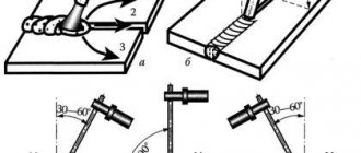
- Bevel angle . On graphic materials and in documentation it is indicated by the letter “β”. Indicates the angle between the end of the part and the beveled surface. The value is usually in the range from 10 to 30 degrees. When cutting only one edge, the angle can be 45 degrees.
- Joint cutting angle . In the job description or on the drawings it is indicated by the letter “α”. The term refers to the size of the angle between already prepared bevels. If the edges were processed equally, then the value is equal to twice the bevel angle. It is logical to assume that the range of its values is from 20 to 60 degrees. It is important to choose the correct opening angle to provide the electrode with access to the root of the seam. Only in this case is good penetration of the joint ensured.
- Dullness . Marked with the letter "C". Designation of the edge angle that has not been processed. It can have either a right angle or an acute one. In the latter case, the process of welding the workpieces will be difficult. Metal burns cannot be ruled out in the thin part of the joint. To correct the situation, experts resort to the so-called blunting of edges. The processing depth can reach two millimeters.
- Gap . Denoted by the symbol “b”. Informs about the size of the gap at the root of the joint. The gap itself is necessary in order to ensure maximum penetration in the root zone. As a rule, its value is about 1.5 mm. Depending on the technical features of welding, the value may increase or decrease.
- Bevel length . In the technical documentation it is marked with the symbol “L”. Designed to ensure a smooth transition from the minimum value of the beveled part to the thickness of the workpieces. It is important to select the correct parameter value. This eliminates tension in the area.
- Height and width . They are indicated by the symbols familiar to such parameters: “h” and “b”, respectively.
- Seam leg . The symbol is expressed through the letter “K”. represents the minimum distance from the surface of one part to the opposite boundary of the weld.
Gas-shielded arc welding connections according to GOST 14771
GOST 14771 establishes the main types, structural elements and dimensions of welded joints made of steels, as well as alloys on iron-nickel and nickel bases, performed by gas-shielded arc welding. This GOST adopts the following designations for welding methods:
- In - in inert gases with a non-consumable electrode without filler metal;
- INp - in inert gases with a non-consumable electrode with filler metal;
- IP - in inert gases and their mixtures with carbon dioxide and oxygen with a consumable electrode;
- UP - in carbon dioxide and its mixture with oxygen with a consumable electrode. When making the root of a multilayer weld using a welding method different from the main method by which the edges are filled, the values of the structural elements of the welded joint must be selected according to the main welding method. In this case, the designation of the welding method should be made as a fraction, the numerator of which indicates the designation of the welding method of the root of the seam, and the denominator indicates the designation of the main welding method.
For welded joints C12, C21, C23, C24, U7, U10, T7, having parts thickness S = 12 mm or more, as well as for connections C15, C16, C25, C27, U8, T8, having part thickness S = 20 mm and more, performed by the UP welding method, a bluntness of C = 5+2 mm is allowed.
Butt welding of parts of unequal thickness in the case of a difference in thickness not exceeding the values indicated in the table. 1, must be produced in the same way as parts of the same thickness; the structural elements of the prepared edges and the dimensions of the weld should be selected according to their greater thickness. To ensure a smooth transition from one part to another, an inclined position of the seam surface is allowed.
Table 1. Permissible difference in thickness of welded parts
If the difference in the thickness of the parts being welded exceeds the values indicated in the table. 1, on a part with a large thickness S, a bevel should be made on one or both sides to the thickness of the thin part S, while the structural elements of the prepared edges and the dimensions of the weld should be selected according to the smaller thickness.
Displacement of the welded edges relative to each other before welding is allowed, no more than:
- 0.2S - for parts up to 4 mm thick;
- 0.1S +0.5 mm - for parts with a thickness of 5-25 mm;
- 3 mm - for parts with a thickness of 25-50 mm;
- 0.04S +1.0 mm - for parts with a thickness of 50-100 mm;
- 0.01S +4.0 mm, but not more than 6 mm - for parts with a thickness of more than 100 mm.
In butt, tee and corner joints with a thickness of more than 16 mm, made under installation conditions, it is allowed to increase the gap between parts (b) up to 4 mm, and the width of the seam can be increased.
The size and maximum deviations of the fillet weld leg (K and K) must be established during design, while the leg size should be no more than 3 mm for parts with a thickness of up to 3 mm inclusive and 1.2 times the thickness of a thinner part when welding parts with a thickness of over 3 mm mm. The permissible deviations of the fillet weld leg are given in table. 2.
Table 2. Permissible deviation of fillet weld leg
Convexity and concavity of a fillet weld up to 30% of its leg is allowed. In this case, the concavity should not lead to a decrease in the value of the gearbox leg established during design. The design value of the leg (Kp) is the leg of the largest right-angled triangle inscribed in the outer part of the fillet weld. With a symmetrical seam, any of the equal legs is taken as a leg Kp, with an asymmetrical seam - the smaller one.
When welding in carbon dioxide with Sv-08G2S electrode wire with a diameter of 0.8-1.4 mm, it is allowed to use the main types of welded joints and their structural elements in accordance with GOST 5264-80, while the leg of the design fillet weld can be reduced to the values given in table 3.
Table 3. The size of the fillet weld leg of welded joints when welding in carbon dioxide, having structural elements, according to GOST 5264-80
Note. The given data does not apply to connections made when welding with an extended electrode extension or with direct current polarity. It is allowed to increase the size of welds up to 30% of the nominal value in places where welds overlap and in places where defects are corrected. When preparing edges using hand tools, the maximum deviations of the edge bevel angle can be increased to +5°, and the seam width can be changed accordingly.
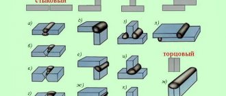
Types of edge preparation
The accepted classification includes all methods known today for cutting the edges of welded metal workpieces. The choice of a specific option is based on the following parameters: type of seam, welding technology used, wall thickness. The species listed in the classification have their own name. It is expressed in the form of a Latin letter, which is similar to the cutting method. Three types have a straight bevel and only one has a curved bevel.
V-shaped
Used most often. Its popularity is due to its ease of execution and versatility: suitable for cutting metal workpieces of various thicknesses in the range from 3 to 26 mm. The method requires cutting both edges. The angle is 60 degrees. Excellent for T, butt and corner joints.
X-shaped
Also a popular option for edge preparation. Bevels are made on both sides. Excellent for preparing parts with wall thicknesses from 12 to 60 millimeters. The cutting angle is 60 degrees. It is welded in several passes on each side, which reduces the consumption of electrodes for forming a seam. When heated, slight deformation may occur.
K-shaped
The method is used very rarely. The edges are prepared only on one part, but on both sides. That is, one of the edges has a straight wall, and the other has two bevels.
U-shaped
The only option for a curvilinear bevel, which, because of its shape, is also called a “glass bevel.” It is precisely because of the shape that this option for cutting edges is the most difficult. It is carried out using special equipment - edge cutters. Its use can only be justified if the quality of the seam must be impeccable. Both edges are prepared on the same side and have identical mirror-facing bevels. Suitable for wall thicknesses from 20 to 60 mm. The method is characterized by low consumption of electrodes.
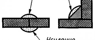
Purpose of cutting edges for welding
Cutting allows you to solve two main problems: penetration throughout the entire thickness of the sheet and high-quality penetration of the root of the seam. The bevel created during cutting ensures a smooth transition from one part to another, which reduces mechanical stress. Without a correctly executed bevel, the electrode will not be able to reach the root of the seam and achieve full penetration. A separate issue is cutting when welding pipes and vessels, as well as welding bends and fittings to pipes.
Preparation of edges for welding
The process of preparing edges for welding can be divided into two stages: cleaning
and
cutting
. Cleaning is carried out in order to remove all foreign inclusions and minor defects in the surface of the part. Edge processing is carried out until the surface has a metallic shine. The part is cleaned on both sides with a strip of up to 20 mm. Next, the ends and blunt ends are cleaned.
For small volumes of work, cleaning is carried out with hand-held metal brushes, files and sanding paper. Places contaminated with oil and preservative compounds are scraped off with scrapers and wiped with solvents. For large volumes of work, mechanical wire brushes or sandblasters are used. Contaminants are combated by etching in solutions of alkalis and acids, followed by rinsing with clean water.
Edge cutting
Depending on the thickness of the metal being welded, cutting is carried out either on one or both sides. In any option, the bevels are made without a sharp edge, and the last millimeters are dulled, achieving a flat edge. Cutting can be done by mechanical processing using the following operations:
- chiselling;
- planing;
- milling.
Straight joints are prepared on planing machines. The forward movement of the cutter allows you to remove excess metal and obtain the desired shape. It is somewhat more difficult to process curved seams. In such cases, it is necessary to use milling machines. The movement of the cutter can be controlled manually, but special programs are more often used. Thus, processing is faster and more accurate. With a complex seam configuration, manual control of the cutter movement is impossible.
When preparing products that cannot be installed on a machine due to their large size or shape, portable edge scrapers are used. They are installed directly on the workpiece and process it. As you might guess, the shape and quality of the chamfer surface leave much to be desired, and the workpiece requires additional processing.
Abrasive processing is used as an additional treatment after milling and chipping, as well as when removing minor flaws on small parts from the surface.
When cutting edges using thermal methods, the following is used:
- gas cutting (oxygen);
- plasma cutting;
- laser cutting.
The use of gas cutting for alloy steels is limited by the formation of difficult-to-remove carbides on the edge surface. This type of cutting is used mainly for preparing products made of carbon steels. Plasma cutting works much better. The high temperature of the plasma allows you to obtain a high-quality edge on workpieces made of any materials. Laser cutting is still extremely rare; it gives excellent results, but is very expensive, so it is used only for cutting seams on the most critical products.
The following edge bevel shapes are used: V-shaped, X-shaped, U-shaped
and
K-shaped
.
V shape
This is the most popular type of cutting. The popularity is easily explained by the comparative simplicity of execution and the possibility of application on metals of various thicknesses.
X shape
Used when welding thick-walled metals.
U shape
This difficult-to-make bevel is used for welding thick-walled metals. It is most often used in manual arc welding, since this results in significant savings in electrodes.
K-shaped bevel
used extremely rarely. It resembles an X-shaped bevel made on one half of the workpiece.
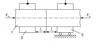
Displacement of edges of welded butt joints
It is not at all necessary that the edges be symmetrical in shape and placed strictly parallel. Their displacement is allowed, but only within certain limits. Such tolerances are regulated in regulatory documentation. The amount of displacement directly depends on the thickness of the parts being connected.
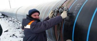
There are some nuances when welding pipelines. Such work requires high precision. The tolerance for displacement here is much tighter than for parts with a flat surface. In order to comply with the regulations and not exceed the maximum permitted tolerances, the pipes are securely fixed before performing welding work. The most common fixing method is tack welding.
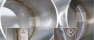
Pipe edges
Everything related to pipeline welding is characterized by increased quality requirements and work regulations. Forming seams on pipe lines is a rather complex and labor-intensive process. The cutting of edges for pipe welding is prescribed in the provisions of GOST 16037.
Much attention is paid to maintaining the perpendicularity of the pipe axis with respect to the end surface. To comply with the requirements, it is necessary to cut the pipe to obtain a right angle before preparing the edges. The opening angle also varies within a small range of values: 60-70 degrees. Blunting of edges by 2-2.5 mm is allowed. Processing of the ends is possible in any available way - manual, mechanical, machine, or gas cutter.
When assembling pipelines, it is important to maintain the alignment of the elements being connected and the precise joining of the surface. No less stringent requirements are imposed on the size of the gaps. They should fit within the range of 2-3 mm. To avoid misalignment of the elements, the gap must be the same around the entire circumference.