How to connect a single-phase asynchronous motor through a capacitor?
At industrial facilities, there are no special problems with how to connect an electric motor; a three-phase network is supplied there.
Asynchronous electric motors operate with three connected windings located around the perimeter of a cylindrical stator. A separate phase is switched on for each winding of the connected motor, the electric motor connection diagram ensures a phase shift of the alternating current, creates torque, and the motors rotate successfully. In the case of living conditions in residential buildings in private houses and apartments, there are no three-phase electric lines; single-phase networks are laid, where the voltage is 220 volts. Therefore, a single-phase asynchronous motor is connected using a different circuit; a device with a starting winding is required.
Connection diagram for a single-phase motor with a starting winding
How to determine the working and starting windings of a single-phase motor
Single-phase motors are low-power electrical machines. The magnetic circuit of single-phase motors contains a two-phase winding, consisting of a main winding and a starting winding.
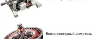
Two windings are needed to cause the rotor of a single-phase motor to rotate. The most common motors of this type can be divided into two groups: single-phase motors with a starting winding and motors with a running capacitor.
For engines of the first type, the starting winding is switched on through a capacitor only at the time of start-up and after the engine has developed a normal rotation speed, it is disconnected from the network. The motor continues to operate with one working winding. The size of the capacitor is usually indicated on the motor nameplate and depends on its design.
Advice
For single-phase asynchronous AC motors with a running capacitor, the auxiliary winding is permanently connected through a capacitor. The value of the working capacitance of the capacitor is determined by the design of the engine.
That is, if the auxiliary winding of a single-phase motor is starting, its connection will occur only during the start-up, and if the auxiliary winding is a capacitor, then its connection will occur through a capacitor, which remains turned on during engine operation.
It is necessary to know the design of the starting and operating windings of a single-phase motor. The starting and operating windings of single-phase motors differ in both the cross-section of the wire and the number of turns. The working winding of a single-phase motor always has a larger wire cross-section, and therefore its resistance will be less.
Look at the photo and you can clearly see that the wire cross-sections are different. The winding with a smaller cross-section is the starting one. You can measure the resistance of the windings using dial and digital testers, as well as an ohmmeter. The winding with less resistance is the working one.
Why is a 220 V motor started via a capacitor?
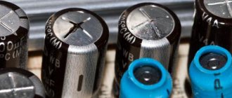
First, let's define the terminology. A capacitor (Latin condensatio - “accumulation”) is an electronic component that stores electrical charge and consists of two closely spaced conductors (usually plates) separated by a dielectric material. The plates accumulate electrical charge from the power source. One of them accumulates a positive charge, and the other accumulates a negative charge.
Capacitance is the amount of electrical charge that is stored in an electrolyte at a voltage of 1 Volt. Capacitance is measured in units of Farad (F).
The method of connecting the motor through a capacitor - this method is used to achieve a soft start of the unit. On the stator of a single-phase motor with a squirrel-cage rotor, another winding is placed in addition to the main electrical winding. Two windings are related to each other at an angle of 90 0. One of them is working, its purpose is to make the motor work from a 220 V network, the other is auxiliary, needed for starting.
Let's look at the capacitor connection diagrams:
- with switch,
- directly, without a switch;
- parallel connection of two electrolytes.
Connecting an electric motor via a capacitor
The topic is very popular and raises many questions. First, let's figure out what types of asynchronous AC motors are available and in what cases connection via capacitors is used. Then we will look at the diagrams and formulas for selecting capacitors.
Motors are divided into three-phase and single-phase according to the method of power supply. First, let's look at connecting a three-phase electric motor through a capacitor.
Briefly about three-phase asynchronous electric motors
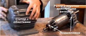
Three-phase asynchronous electric motors are widely used in various industries, agriculture, and everyday life. The electric motor consists of a stator, a rotor, a terminal box, shields with bearings, a fan and a fan casing.
I did not remove the tightening pins to get to the stator with the rotor. But the protruding part on which the fan sits is the rotor. The rotor is the rotating part, the stator is stationary (it is not visible in the figure).
Next, let's look at the terminal strip more carefully. On one side we have C1-C2-C3, and below – C4-C5-C6. These are the beginnings and ends of the motor phase windings. We have three phases, since the motor is three-phase - C1-C4, C2-C5, C3-C6. There is also a rusty grounding bolt in the photo; it is located in the terminal block on the top left.
The connection that is visible in the photograph is called a “star”. I have already written about star and triangle for transformers - similarly for electric motors. On the side of the photo I added what a schematic star and triangle look like for this electric motor. The whole difference is in the location of the jumpers. Their combinations determine the ED connection scheme.
operation of a three-phase electric motor without one phase at a constant load
The electric motor can operate from a single-phase network and without additional measures and circuits. For example, if one of the phases is damaged. However, in this case the rotation speed will decrease. Reducing the rotation speed will lead to an increase in slip, which in turn will cause an increase in motor current.
And an increase in current will lead to heating of the windings. In such a situation, it is necessary to unload the ED to 50%. Operation in this mode is possible, however, if the engine stops, it will not be possible to start again.
why are capacitors used to start from a single-phase network?
A restart will not occur, since the magnetic field of the stator will be pulsating and, in short, due to the direction of certain vectors in opposite directions, the rotor will be motionless. In order for the engine to start, we need to change the location of these vectors. For this purpose, elements are used that shift the phases of vectors. Let's consider a circuit that implements this feature.
In the diagram we see that the winding is divided into two branches - starting and working. The starting one is used from the beginning of the start until the engine turns, then it is turned off and only the working one is used. To turn off the launcher, you can use a button, for example. Press and hold until the engine turns, and then release and the chain is broken.
Important
Phase-shifting elements can be resistors or capacitors. The difference is in the use of one or the other in the form of the magnetic field. And to put it simply, they choose capacitors, since at the same value of the starting torque, the starting current will be lower when using capacitors.
And with the same starting currents, circuits with a capacitor will have a greater initial torque, that is, the engine will accelerate faster, which is undoubtedly better for operation.
how to connect an electric motor through a capacitor
Since capacitors are more profitable in many ways for starting electric motors, we will analyze a couple of starting circuits using capacitors. For the “delta” connection diagram and for the “star” connection diagram.
The starting branch will be used until the motor turns around, the working branch will be used throughout the entire operation of the engine.
capacitors for starting an electric motor
It would be logical to further figure out how to calculate the starting and running capacitors for the engine. For correct selection, we need to know the passport data of the ED, or have a nameplate with factory values.
There are various schemes and in each capacitors are selected differently. For the circuits given above, the selection of capacitors is carried out according to two formulas:
In the formulas above, In is the rated phase current of the electric motor. If you look at a plate where two currents are indicated through a fraction, it will be the smaller of them. Umains – supply voltage (~127, ~220).
This means that we have calculated the capacitance and the next step is to know the voltage across the capacitor. For the circuits shown in the figures above, the voltage on the capacitor is equal to 1.15 of the mains voltage.
But this is AC voltage, and to select capacitors you need to know the DC voltage. This is where we need a small sign:
For example, the network voltage is ~220, multiply by 1.15 and we get 253. In the table we look at the variable 250 corresponds to a constant of 400V for a capacitance of up to 2 µF, or 600V for capacitances of 4-10 µF. It is necessary that the rated voltage of the capacitor is equal to or greater than the calculated one.
Next, knowing the operating voltage and the required capacity, we select capacitors according to the parameters: types and required quantity. Capacitors for the starting circuit are sometimes called starting capacitors.
So, step by step, we figured out how to connect a three-phase asynchronous electric motor to a single-phase network and what you need to calculate and know for this. There are other schemes for connecting a motor through a capacitor, but we will consider these issues another time in another article.
Source: https://pomegerim.ru/elektricheskie-mashiny/podklu4enie-trehfaznogo-ed-4erez-kondensator.php
Connection diagram for a 3-phase motor in a 220V network connected by a star.
As you can see, the 220V voltage is distributed over two series-connected windings, where each is designed for such a voltage. Therefore, the power is lost almost twice, but such an engine can be used in many low-power devices.
The maximum power of a 380V motor in a 220V network can only be achieved using a delta connection. In addition to minimal power losses, the engine speed also remains unchanged. Here, each winding is used for its own operating voltage, hence the power. The connection diagram for such an electric motor is shown in Figure 1.
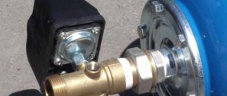
Fig. 2 shows a terminal with a 6-pin terminal for delta connection. The three resulting outputs are supplied with: phase, zero and one terminal of the capacitor. The direction of rotation of the electric motor depends on where the second terminal of the capacitor is connected - phase or zero.
In the photo: an electric motor with only working capacitors and no capacitors for starting.
If there is an initial load on the shaft, it is necessary to use capacitors for starting. They are connected in parallel with the workers using a button or switch at the time of switching on. As soon as the engine reaches maximum speed, the starting tanks should be disconnected from the workers. If it is a button, we simply release it, and if it is a switch, then we turn it off. Then the engine uses only working capacitors. Such a connection is shown in the photo.
Connecting a three-phase motor to a single-phase network
There are times when it is necessary to connect an electrical appliance differently than indicated in its instructions.
For example, it is often necessary to connect a three-phase motor to a single-phase network , which, although it reduces the power of the device, is in some cases quite justified.
note
There are basic wiring diagrams for these electric motors, which are successfully and widely used in practice. There are also certain nuances that help solve unexpected difficulties associated with the lack of certain materials.
This is especially true for powerful industrial devices. Outside an apartment or private house, there are no problems with a three-phase connection. How can you connect a three-phase motor to a single-phase network when there are two wires on your meter?
Standard method of connecting an electric motor
A three-phase electric motor has three windings located at an angle of 120 degrees. There are 3 pairs of contacts per terminal block. Their connection can be organized in several ways.
Star connection
At one end, each winding is connected to the other two windings, thus creating a neutral. The remaining ends are connected with three phases. So, 380V is supplied to all individual pairs of windings.
The jumpers in the distribution block are connected accordingly; it is simply impossible to confuse the contacts . In alternating current there is no concept of polarity, therefore it does not matter which phase is supplied to a particular wire.
Connection using the "triangle" method
With this option for connecting an electric motor, the end of each winding is connected to the next, thus creating a vicious circle, that is, a triangle . All windings have a voltage of 380V.
Thus, jumpers are placed differently on the terminal block. Similar to the first connection method, there is no polarity as a class.
Voltage is supplied to all groups of contacts at different times, following the definition of “phase shift”. Therefore, the magnetic field drags the rotor along with it, creating a constant torque. This is how an electric motor works with a “native” three-phase connection.
What to do when you get an electric motor in good condition, but you need to connect it to a single-phase power supply? There is no need to be upset; the connection diagram for a three-phase electric motor was created long ago by engineers. Let's look at several of the most common connection methods .
Connecting a three-phase electric motor to a 220V power supply (single phase)
The operation of a three-phase electric motor when connected to one phase, at first glance, is no different from correct switching on. The rotor spins, almost without losing speed, there are no slowdowns or jerks.
But it will not be possible to achieve standard power with this power supply . This is a forced loss that cannot be corrected in any way; it must be taken into account.
Taking into account the control circuit, the power reduction can fluctuate around 25-50%.
Moreover, the electricity consumed is the same as if you were using all the power. To choose the most profitable method , we suggest getting acquainted with different connection options.
How to check an electric motor for performance
There are several options for the user to check the engine for performance.
• Analysis of the external state of the device. Overheating of the system is associated with darkening of the paint on the engine in the middle part.
• Check the manufacturer's specifications indicated on the device label. Don't expect the engine to produce more power and RPM than what it says on the label.
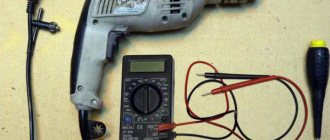
• Take readings using a multimeter.
• Run hardware diagnostics on the device.
Checking the power of the electric motor.
The electric motor faces a large load during operation of a single or complex system. An experienced user knows that any device, even the most reliable, fails over time. Therefore, it is important to take readings of the electric machine several times after installation, both the motor power and other values.
• Power can be determined by the meter.
• The power parameter is calculated based on the tables (data will be needed, for example, shaft diameter D, S cm/m to the axis, motor length).
• Data on engine dimensions also serve as an aid to calculating engine power.
• The power is directly determined based on the shaft rotation speed. The frequency is multiplied by k 6.28, the force and the radius of the system (found using a caliper).
Connection diagrams
Let's look at both connection schemes. Let's start with a triangle. In any circuit, it is very important to connect the capacitor correctly. In this case, the wires are distributed as follows:
- Two contacts are connected to the network.
- One through the capacitor to the winding.
But there is one point: if the electric motor is not loaded, then its rotor will begin to rotate without any problems. If the start-up is carried out under a certain load, the shaft will either not rotate at all, or at a very low speed. To solve this problem, it is necessary to install another capacitor in the circuit - a starting capacitor. It has only one task - to start the engine, switch off and discharge. In fact, the starter only works for 2-3 seconds.
Reversal methods
To change the direction of rotation of three-phase asynchronous motors connected to a household network of 220 volts 50 Hertz, the same principle is applied as for those that have not undergone alteration. When connecting the windings with a star or triangle, one connection point of the capacitor must be changed, and for an independent starting winding, both connection points of its terminals are swapped.
Despite the fact that changing the power type of a three-phase asynchronous motor is not a process contrary to the laws of electrical engineering and does not violate electrical safety rules, it cannot be considered completely normal and generally accepted. If possible, it is better to use equipment whose design elements correspond to each other and are not the result of “dancing with a tambourine.”
Use of asynchronous motors
Three-phase and single-phase asynchronous motors are actively used in various sectors of the economy. There are several reasons for this:
- Simplicity of design.
- Reliability and durability during use.
- In order to start the engine, there is no need to use expensive and scarce devices.
- The motor does not require too frequent maintenance.
By appearance, you can easily distinguish three-phase motors from single-phase ones. The former always have 6 terminals, while the latter have two or four.
For three-phase motors, the windings are connected in two ways: star or delta. They assume the use of a voltage of 380 volts. However, it is rarely used in everyday life. To use such a motor, you need to know how to connect it correctly.
This is done using a phase-shifting capacitor. This will allow the use of three-phase motors when connected to a single-phase network. In this case, the motor power will be equal to 50% -60% of the nominal.
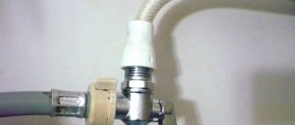
Checking the starting capacitor Source antemion.ru
Optimal operation of a three-phase motor is ensured by using a variable capacitance. To do this, at the first stage, working and starting capacitors are used, and at the second, only the first of them.
Asynchronous single-phase motors are often used in everyday life. Additional winding is usually required to start.
When choosing the capacitance of a capacitor, it is necessary to take into account how the magnitude of the starting torque depends on it. As this characteristic increases, the force increases. At a certain value it becomes maximum. After a further increase, the starting torque will begin to fall.
Calculation of capacitor parameters Source uk-energotekhservis.rf
Connecting an electric motor 380V to 220V
General rules for connecting an electric motor through a capacitor.
The 380V to 220V electric motor is connected via a capacitor. For such a connection, it is necessary to use paper (or starting) capacitors , and it is IMPORTANT that the rated voltage of the capacitor is greater than or equal to the mains voltage (it is recommended that the capacitor voltage be 2 times the mains voltage). The following brands (types) of capacitors can be used:
MBGO, MBGCh, MBGP, MBGT, MBGV, KBG, BGT, OMBG, K42-4, K42-19, etc.
The capacitance of the capacitor can be determined using the formulas given below, or using an online capacitance calculation.
The first thing you need to do is to correctly connect the leads of the motor windings. As is already known from the article: connection diagrams for electric motor windings electric motor windings can be connected according to a “star” circuit (denoted by Y) or by a “delta” circuit (denoted by Δ), while, as a rule, a “triangle” circuit is used to connect a 220V electric motor "In order to determine the winding connection diagram, you need to look at the passport data of the electric motor on the nameplate attached to it:
The entry: “Δ/ Y 220/380V” means that to connect this electric motor to 220V, you need to connect its windings in a delta , and to connect to 380V, in a star ; read how to do this here .
How does a three-phase asynchronous motor work?
In most cases, asynchronous motors use capacitor starting, but there are other starting methods. In three-phase electric motors, unlike single-phase ones, there are three stator windings, which are shifted at a certain angle. The winding angle of the stator windings of a three-phase motor is 120 degrees, which allows you to create a powerful magnetic field around the rotor.
The stator design of a three-phase electric motor consists of the following elements:
- Housings;
- Magnetic core and core with windings;
- Terminal box.
The standard connection of the windings of a three-phase electric motor is made according to the “star” circuit. There is also a less common way to connect the windings of a three-phase motor, namely, a “triangle”. In any case, each stator winding has a specific direction, as well as a beginning and an end.
Arabic numerals are used to number the stator windings of an electric motor: 1, 2, 3. The ends of the windings are designated by a letter and a number: K1, K2, K3, and their beginnings are H1, H2, H3. In some types of electric motors, the marking of the stator windings may have a different designation, for example: C1, C2, C3 and C4, C5, C6.
Model overview
There are several popular models that can be found on sale.
It is worth noting that these models differ not in capacity, but in type of design:
- Metallized polypropylene versions of the SVV-60 brand. The cost of this version is about 300 rubles.
- NTS film brands are somewhat cheaper. With the same capacity, the cost is about 200 rubles.
- E92 – products of domestic manufacturers. Their cost is small - about 120-150 rubles for the same capacity.
There are other models, often differing in the type of dielectric used and the type of insulating material.