material provided by SIDOROV Alexander Vladimirovich
During the manufacturing process of machines, some of their parts are connected to each other, and permanent or detachable connections are formed. []
One-piece
are connections that cannot be disassembled without breaking or damaging parts. These include riveted, welded, adhesive, soldered, and conditionally interference fit joints.
Detachable
are connections that can be disassembled and reassembled without damaging parts. Detachable connections include threaded, keyed, splined and other connections.
Welded joints
are formed by local heating of parts in the welding zone. Electrical types are the most widespread, the main ones being arc and resistance welding.
The following types of arc welding
:
- automatic submerged arc welding (this type of welding is highly productive and economical, produces good seam quality, and is used in large-scale and mass production for structures with long seams);
- semi-automatic submerged arc welding (used for structures with short intermittent seams);
- manual welding (used in cases where other types of arc welding are irrational, this type of welding is low-productive, the quality of the weld depends on the qualifications of the welder).
contact welding
used in serial and mass production for lap joints of thin sheet metal (spot, seam contact welding) or for butt joints of round and strip metal (butt contact welding).
Advantages of welded joints
:
- low cost of connection due to low labor intensity of welding and simplicity of weld design;
- relatively small weight of the structure (15-25% less than the weight of the riveted one):
- due to the absence of holes for rivets, a smaller area of welded parts is required;
- the parts can be connected without overlays;
- there are no protruding massive rivet heads;
Disadvantages of welded joints
:
- the strength of the weld depends on the qualifications of the welder (it can be eliminated by using automatic welding);
- warping of parts due to uneven heating during the welding process;
- insufficient reliability under significant vibration and shock loads.
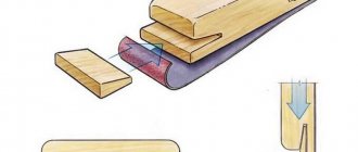
Interference connections
are carried out by selecting the appropriate fits, in which the interference is created by the necessary difference in the landing dimensions of the parts placed on one another. The mutual immobility of the connected parts is ensured by friction forces arising on the contact surface of the parts.
Connections of parts with interference are conventionally classified as permanent connections, although, especially with hardened surfaces, they allow disassembly and reassembly of parts. For this use:
- mechanical interface;
- thermal landings;
- cooling of the covered part.
Advantages of interference connections
:
- simplicity of design and good alignment of the parts to be connected;
- high load capacity.
Disadvantages of interference connections
:
- complexity of assembly and, especially, disassembly;
- dissipation of joint strength due to fluctuations in actual fitting dimensions within tolerances.
Threaded connections
are the most common detachable connections. They are formed by bolts, screws, studs, nuts and other threaded parts.
Threads are classified
depending on the:
- shape of the surface on which the thread is formed: cylindrical;
- conical;
- triangular;
- right (the helix rises from left to top to right);
- single-pass;
- fastening (used in threaded connections; they have a triangular profile, which is characterized by high friction, which protects the thread from self-unscrewing, as well as high strength and manufacturability);
Advantages of threaded connections
:
- high load capacity and reliability;
- availability of a large range of threaded parts for various operating conditions;
- ease of assembly and disassembly;
- low cost due to standardization and high-performance manufacturing processes.
Disadvantages of threaded connections
:
- the presence of a large number of stress concentrators, which reduce fatigue resistance at variable stresses.
Keyed connections
consist of a shaft, key and hub of the female part.
Key
is a beam inserted into the grooves of the shaft and hub to transmit torque between the shaft and the female part.
Keyed connections are divided into
on the:
- unstressed (when assembling connections, no pre-stresses arise in the parts): with parallel keys (the working edges are lateral, they do not hold the parts from axial displacement along the shaft) based on the shape of the ends they are distinguished: with rounded ends (Figure 1, version 1);
- with flat ends (Figure 1, version 2);
- with one flat and the other rounded end (Figure 1, version 3);
- with wedge keys (they have the form of single-bevel self-braking wedges with a slope of 1:100, do not require locking the hub from longitudinal movement along the shaft, and are good at absorbing shock and alternating loads) (Figure 3);
Figure 1 – Connections with parallel keys
Figure 2 – Connection with a segment key: 1 – setscrew; 2 – spring lock ring
Figure 3 – Connection with a taper key
Figure 4 – Connection with tangential keys
Advantages of keyed connections
:
- simplicity of design;
- comparative ease of installation and dismantling.
Disadvantages of keyed connections
:
- the keyway weakens the shaft and hub of the female part not only by reducing the cross-section, but, most importantly, by a significant concentration of bending and torsion stresses;
- labor-intensive manufacturing.
Spline connections
are formed by protrusions - teeth on the shaft and corresponding depressions -
splines
in the hub of the female part. The working sides are the sides of the teeth. Simply put, spline connections can be considered as multi-key connections.
Spline connections are distinguished
:
- by the nature of the connection: fixed (for securing the female part to the shaft);
- movable (allow the part to move along the shaft);
- by outer diameter (most technologically advanced);
- straight-sided (have a constant thickness of teeth) (Figure 5);
Figure 5 – Straight spline connection
Figure 6 – Involute spline connection
Figure 7 – Triangular spline connection
Advantages of spline connections
(compared to keyed connections):
- provide better alignment of the parts to be connected and more accurate direction during axial movement;
- the number of connection parts is reduced (a spline connection is formed by two parts, a keyed connection is formed by three or four);
- with the same dimensions, they allow the transmission of large torques due to the larger contact surface;
- ensures high reliability under dynamic and reverse loads;
- the shaft is weakened slightly by the teeth;
- The length of the hub decreases.
Disadvantages of spline connections
(compared to keyed connections):
- more complex manufacturing technology;
- higher cost.
Questions for control
- What are the main types of connections?
- What types of welded joints are there?
- What are the advantages and disadvantages of welded joints?
- What methods are there for assembling and disassembling interference joints?
- What are the advantages and disadvantages of interference fit connections?
- What types of threaded connections are there?
- What are the advantages and disadvantages of threaded connections?
- What types of key joints are there?
- What are the advantages and disadvantages of keyed joints?
- What types of spline joints are there?
- What are the advantages and disadvantages of spline joints?
| < The concept of interchangeability of parts | Content | Axles, shafts, supports > |
3.7 3 votes
Article rating
Connections of metal structures
During the construction of structures, elements of metal structures must be connected to each other. These connections are made using electric welding, bolted and riveted connections.
Welded joints.
This is the most common type of connection on construction sites. It ensures reliability, strength and durability of connections, ensures tightness of connections (water and gas tightness), and when using high-performance equipment, helps reduce construction time and cost. The main type of welded joints is electric arc welding, based on the occurrence of an electric arc between the elements being welded and the electrode. The arc provides a high temperature, on the order of thousands of degrees Celsius, and due to this, the electrode melts and the metal of the parts being welded penetrates. This results in a common weld pool of liquid metal, which, when cooled, turns into a weld.
About 70% of all welding work is performed using manual arc welding (MAW). This type of welding requires a minimum of equipment: welding transformers, electrical cables, electrodes with appropriate coating and the organization of a welding station. During welding, the electrode coating melts and partially evaporates, forming liquid slag and a gas cloud around the welding site. This ensures stable arc burning, protection of the welding zone from atmospheric air and cleaning of the weld metal from harmful impurities (phosphorus and sulfur). The disadvantage of this type of welding is its relatively low productivity. To obtain better quality seams and increase labor productivity, automatic (ADS) and semi-automatic welding under a layer of flux and in a carbon dioxide environment is used.
With these types of welding, a welding electrode in the form of a wire is automatically fed into the welding zone, and flux or carbon dioxide is also supplied there. These substances perform the same function as coating the electrode. In semi-automatic welding, the movement of the electrode along the seam is carried out manually. For welding thin sheets (up to 3 mm), either resistance spot welding or roller welding is used. Depending on the location of the joined elements, there are butt, overlap, corner and combined joints. In butt joints, the joined elements are in the same plane, and in overlap joints they overlap each other. The main types of welded joints are presented in Fig. 5.1. Depending on which edges of the mating elements are welded a) b) c) d)
Fig.5.1 Types of welded joints:
a – butt, straight and oblique seams; b - overlapped with flank seams; c – overlapped with frontal seams; d – joint with overlays with flank seams
e) f) h) g)
Fig.5.1. Continuation;
d – joint with overlay with frontal seams; e – with a combined lining; h – corner joint in the tee; g - corner joint, frontal and flank seams are distinguished, and depending on the position in space during welding work - bottom, horizontal, ceiling, and vertical seams, Fig. 5.2.
Rice. 5.2. Position: a – butt and b – fillet welds in space;
1 – bottom seam, 2 – horizontal, 3 – vertical, 4 – ceiling
Elements of metal structures made of aluminum are welded using argon-arc welding.
The calculation of welded joints depends on the type of joint and on the orientation of the seam in relation to the applied forces. Calculation of butt welds under the action of axial force is carried out according to the formula:
N/(t lw) ≤ Rwy?c, (5.1)
where N is the calculated value of the force; t is the smallest thickness of the sheets being welded;
lw is the design length of the seam, Rwy is the design resistance of butt welded joints and ?c is the operating conditions coefficient. The estimated length of the seam is equal to its physical length minus the initial section of the seam - the crater and the final section - lack of penetration. In these areas, the welding process is unstable and the quality of the seam does not meet the requirements. In this case lw = l - 2t. Destruction of frontal and flank seams occurs due to shear forces, see Fig. 5.3. The cut can occur along two planes - along the weld metal and along the metal at the fusion boundary, sections 1 and 2 in Fig. 5.4.
Rice. 5.3. Weld seam cutting diagram:
a – destruction of flank seams, c – frontal seams
The strength of the weld metal is checked using the formula:
N / ( βf kf lw ) ≤ Rwf ?w ?c , ( 5.2 )
and along the fusion boundary according to the relationship:
N / ( βz kf lw ) ≤ Rwz ?wz ?c , ( 5.3 )
where lw is the design length of the seam; kf – seam leg; ?w and ?wz – coefficients of weld operating conditions; ?c—working conditions coefficient; Rwf is the design shear strength of the weld; Rwz—calculated resistance along the fusion boundary; βf and βz are coefficients depending on the type of welding, the diameter of the welding wire, the height of the weld leg and the yield strength of the steel.
Rice. 5.4. To calculate a welded joint with a fillet weld:
1 – section along the weld metal; 2 – section along the fusion boundary
When designing welds in steel structures, a number of design requirements must be met. The thickness of the welded elements should not be less than 4 mm and not exceed 25 mm. The minimum design length of the fillet weld should not be less than 40 mm, and the maximum should not be more than 85 βf kf. The thickness of the weld is limited by the maximum value of its leg kf ≤ 1.2 t, where t is the smallest thickness of the elements being connected.
Bolted connections. These are connections in which structural elements are connected to each other using bolts. Compared to welded joints, bolted joints have the advantage of ease of mating elements and greater factory readiness, but lose in higher metal consumption and greater deformability. The increased consumption of metal is due to the weakening of the joined elements by the holes for the bolts and the consumption of metal on the linings, bolts, nuts and washers, and the increased deformability is due to the fact that under the influence of the load there is a selection of leaks in the junction of the bolts and the walls of the elements being connected.
Bolts come in regular and high-strength types. Ordinary bolts are made of carbon steel by cold or hot heading. High-strength bolts are made of alloy steel. Bolts, except self-tapping ones, are made with a diameter of 12 to 48 mm with a rod length of 25 to 300 mm. Bolts vary in accuracy classes. Class C is for rough precision, normal accuracy is class B and class A is for high precision bolts. The difference in classes lies in the deviations of the diameter of the bolts and holes for them from the design diameter. For bolts of classes C and B, deviations in their diameter can reach 1 and 0.52 mm, respectively. The holes in the joining elements for bolts of classes C and B are made 2 - 3 mm larger than the diameter of the bolt, and for class A the diameter of the holes should not be more than 0.3 mm than the diameter of the bolt.
Plus tolerance for the bolt diameter and minus tolerance for the hole are not allowed in this case. The difference in the diameters of the bolt and hole facilitates the assembly of connections, however, this difference causes increased deformability of bolted connections, since under the influence of load, leaks in the junction of the walls of holes and bolts occur. The same difference in size leads to uneven operation of individual bolts in the connection. Therefore, class B and C bolts are not recommended for use in critical shear connections. In critical structures, ordinary class A bolts or high-strength bolts are used.
High-strength bolts are bolts of normal accuracy, they are placed in holes of larger diameter. These bolts are tightened using a calibration wrench, which allows you to control the tightening force and the tension force of the bolt. High-strength bolts are used to increase the load-bearing capacity of connections. This is achieved by the fact that with controlled tension on the nuts, the joined sheets are pulled together so tightly that they ensure the perception of shear forces in the joint due to friction. With such joints, it is necessary that the thickness of the joined elements be strictly the same, otherwise it is impossible to press the joint plate tightly enough to both elements.
In addition, special treatment of the mating surfaces is necessary (cleaning them from oil, dirt, rust and scale) to increase their adhesion ability. In addition to friction connections on high-strength bolts, there are connections that absorb forces through the combined work of the forces of friction, crushing and shearing of the bolts. Another type of bolted joints are glued joints. In this case, the elements of metal structures are first glued together and then tightened with bolts. Finally, to connect thin and sheet joints, self-tapping bolts are used, which are usually made with a diameter of 6 mm.
Ordinary bolts, when a load is applied to the assembly, work on bending and tearing off the head, shearing the bolt, crushing the surfaces of the bolt and hole, and tension, Fig. 5.5, and the joined sheets for tearing out the edges. As the load increases, the shear work of a bolted connection can be broken down into four stages. At the first stage, when the frictional forces between the sheets being connected are not overcome, the bolt experiences only
Rice. 5.5. Types of stress state of a bolted connection:
a – bending of the bolt rod; b – cut of the bolt rod; c – collapse of the walls of the holes in the mating sheets; d – central tension of the bolt; tensile stresses from tightening the nut, and the entire connection works elastically.
As the load increases, the forces of internal friction are overcome and the entire connection shifts by the amount of the gap between the bolt and the hole. In the next third stage, the bolt shaft and the edges of the hole are gradually crushed, the bolt bends and stretches, which is prevented by the head and nut of the bolt. With a further increase in load, the bolt enters the elastoplastic stage of operation and is destroyed by shearing, crushing, puncturing one of the connected elements, or tearing off the bolt head.
The calculation of a bolted connection is carried out as follows. The load-bearing capacity of one bolt is determined, and then the required number of bolts in the connection.
The load-bearing capacity of a bolt under shear conditions is determined by the relation:
Nb = Rbs ?b A ns ?c , (5.4)
where Nb is the design shear force perceived by one bolt; Rbs – design shear resistance of the bolt material; ?b – coefficient of connection operating conditions; A – cross-sectional area of the bolt rod (on the unthreaded part); ns – number of calculated cuts of one bolt; ?c – coefficient of operating conditions of the structure.
The bearing capacity of a connection is usually determined based on the collapse of the walls of the joined elements (the bolt material is usually stronger)
Nb = Rbp ?b db ?c ∑ t , (5.5)
where Rbp is the design resistance of the bolted connection to crushing; db—bolt diameter;
∑ t is the smallest total thickness of elements crushed in one direction.
The design force absorbed by the bolt in tension is determined by the formula Nb = Rbt Abn?c, (5.6)
where Rbt is the calculated tensile strength of the bolt material, Abn is the net cross-sectional area of the bolt taking into account threading.
The number of bolts in a connection n under the action of a shear force N applied at the center of gravity of the connection is determined based on the condition of equal strength of all bolts according to the formula
n = N/Nmin, (5.6)
where Nmin is the smallest value determined from relations (5.5) and (5.6);
and when the bolts work in tension, the value is from the ratio (5.6).
When working a joint in shear, in addition to checking the strength of the bolts in the connection, it is necessary to check the tensile strength of the joined elements, taking into account the weakening of their sections by holes, and the puncture (shear) strength of the edges of the joined elements. The latter check is usually not carried out, since the distance of the first row of bolts from the edge of the sheet is chosen in such a way that the puncture strength is guaranteed.
Riveted joints are similar in nature to bolted joints, and the calculation of rivet joints is similar to the calculation of bolted joints.
Currently, they are almost never used due to their high labor intensity and low productivity. They are interesting in that, firstly, they provide a tight connection, since when cooling the rivet contracts and pulls together the joined elements and, secondly, the body of the rivet completely fills the hole in the joined elements due to plastic deformations of the heated metal during the riveting process. Currently, rivet joints are used in steel structures subject to vibration and alternating loads and in aluminum structures, since the use of high-strength aluminum alloys excludes the use of electric welding.
Fig.5.6. Joints of sheet elements:
a – with double-sided overlay; c – with one-sided overlay
Based on structural characteristics, two types of bolted and riveted connections are distinguished - joints and attachment of elements to each other. Sheet metal joints are made using overlays: single-sided or double-sided, Fig. 5.6. Double-sided overlays are preferable, as they provide a symmetrically stressed state of the joint. Joints with a one-sided overlay provide an eccentric connection, bending moments arise in it, and therefore the number of bolts required by calculation is increased by 10%. Joints of profile metal, Fig. 5.7, are made using overlays - corner or sheet. Attaching elements to each other
Rice. 5.7. Bolted and riveted joints of rolled profiles:
a – corner profiles; c – channels; 1 – corner pad; 2 – chamfer; 3 – gasket;
4 – sheet overlays are also carried out using sheet overlays, gussets or corner elements.
Bolts or rivets in connections are placed in a row or in a checkerboard pattern at a minimum distance from each other, which ensures puncture strength and ease of installation of the bolts. The diagram of butt connections of sheet and angle elements working in shear is shown in Fig. 5.8.
Rice. 5.8. Layout of bolts and rivets in shear connections
Welded, bolted and riveted connections have standardized symbols on construction drawings, Fig. 5.9.
Rice. 5.9. Symbols for welds, bolts and rivets in connections:
a – round hole; b – foramen ovale; c – permanent bolt; g – temporary bolt;
d – high-strength bolt; e - rivet
An intermediate position between bolted and rivet connections is occupied by connections using lock bolts (bolts with crimp rings). They are used mainly for connections in aluminum structures and the diameter of these bolts ranges from 6 to 14 mm.
Characteristics of types of Internet
Login methods differ in technology and tariffs for use. The quality of radio communications depends not only on the power of the devices used, but also on the services of suppliers, called providers.
Online operators provide wired and wireless communication lines to subscribers.
In large cities, companies provide customers with a large selection of technologies for using the Internet, and from a variety of proposals you can choose a convenient offer. In small settlements, services are insignificant and you have to give preference to what is available.
Wired connection is currently considered the most reliable and stable, and at the same time economical. Ethernet is a fixed broadband access to a radio network, built on fiber optic or copper cable, which makes it possible to transfer data to computers at high speed.
The high speed of a leased line determines the ability to comfortably work on the Internet. This is one of the best ways to enable online at home and offices.
Note! For access via a dedicated line, operators offer unlimited Internet - the right to enter without any restrictions. The subscriber pays a fixed subscription fee and can be on the Internet for the time he needs .
Using a Wi-Fi router, you can connect other digital devices (smartphone, tablet, laptop) to it.
XDSL technologies provide high-speed digital input over the subscriber telephone line. Accessing the Internet using the old Dial-Up technology is a lengthy connection process, especially when the line is busy (it is impossible to use the phone during an Internet session).
Using ADSL makes it possible to use the Internet and simultaneously make phone calls. An ADSL splitter splits the telephone signal into a regular telephone signal and a high-frequency modem signal. The advantage of ADSL, compared to a leased line, is that existing telephone cables are used, and there is no need to install new ones.
Several years ago, this type of signal transmission was considered one of the best, but now it is used where there is no other online connection.
Data transmission using DOCSIS technology (via coaxial television cable) in two-way mode also occurs through a special modem. Using a splitter, the signal is distributed into television and Internet signals.
If a television cable is already in the house, then you can take advantage of this opportunity so as not to lay additional wires.
Mobile Internet access is becoming more popular than cable access. It has become in demand with the growing popularity of smartphones and tablets. The advantage of mobile support is the possible transmission of the signal anywhere in the coverage area. Cons: signal speed and tariffs.
Note! 3G technology with speeds up to 10 Mb/sec. used throughout most of the coverage areas of major operators. New developments in 4G/LTE technology, allowing speeds of up to 300 Mb/sec, are common only in large populated areas.
The most common option
Don't know what to choose? Do you have a login and password from your provider? Choose PPPoE! This is especially true for Rostelecom.
The second current option in Russia is Dynamic IP.
PPPoE is the most common type of Internet connection in our countries. And in most cases, when the cord comes to you from the entrance, and the login and password for connection are specified in the contract, you need to choose it. Try it, you won't lose anything!
The easiest way
If the previous option didn’t work, and you don’t really want to check all the options, call your provider. I assure you, they will quickly tell you everything, so much so that before you even blink an eye, the Internet will appear everywhere. These are their services, these are their works - they will definitely help you understand the issue.
If you don’t like to make calls, look at the provider’s website from the same mobile phone. Usually they write instructions and provide documentation. If this is not possible, look up the contract; they usually write there the type of connection and all the necessary data to establish it.
MAC address
Another important point is the Mac address. If the Internet provider specifies the mac address, then entering the exact data in the router will not start the network. All valid addresses must be provided. It is important to understand that the main purpose of the router is to provide access to the connection to different devices. This can be a cable network or a wireless connection. For this reason, it is important that during setup every single parameter is entered correctly and, most importantly, the connection type (WAN Connection Type) is correctly selected.