Risk
- a marking line drawn on the surface of the workpiece using a pencil or other object with a pointed end.
A mark, derived from the word “to draw,” is a thin marking line of arbitrary length applied to the surface of a material or workpiece. The main purpose of the mark is not to draw an image of the future product, but to indicate its contours and the boundaries of processing the material or workpiece at this stage of work. A mark is an element of precise marking used in production. At the same time, marking with marks is used exclusively in single-piece production of products and occasionally in small-scale production.
Methods of applying marks
Marking can be done according to a template, drawing, sample, pattern, as well as directly on site by direct measurements. The choice of method for applying marking marks and their number depends on the required accuracy in the manufacture of the product. But in any case, the thickness of the mark should not exceed half a millimeter. Errors made when applying marks to the workpiece lead to the production of a defective product.
After a certain stage of work, all risks or part of them will be erased, covered and cut off. Before the next stage of work, you must make sure that all previously applied risks have been removed, and on those materials where removal is impossible, they must be marked as already used, for example, by crossing them out. Even before applying the marks, you should apply them in such a way that none of them remains on the surface of the finished product.
Marking metal blanks
After the metal is straightened and thoroughly cleaned, the surface to be treated is marked. In fact, marking is already a metalworking operation, but since during its course the workpiece is not directly processed, it would be more correct to consider it a preparatory operation.
What does it mean to mark a workpiece? This means applying marking lines, or marks, to the workpiece, indicating the boundaries to which it must be processed so that it turns into the desired part in the hands of a mechanic. Marking is a very important stage in locksmith work. If a part is marked incorrectly, it simply will not fall into place in the mechanism that the mechanic is repairing.
In order for the marking lines to stick firmly to the metal and not be erased during processing, the surface to be processed must be pre-painted. For this, it is best to use copper sulfate: it adheres well to the cleaned metal - on the thin layer of copper that forms on the surface, the marks are clearly visible.
You can use paint or varnish for the same purpose, of course one that dries quickly. It is also convenient to work with chalk diluted to the thickness of milk, to which you need to add a drier or wood glue so that the chalk dries faster and sticks to the surface more firmly. During dyeing, you need to rub the dye so that it spreads over the entire surface in an even layer, without stains.
If the workpiece is large, then you should paint only those places where marking marks will be applied.
It is often necessary to widen a hole in metal, make a thread, or move the hole a few millimeters to the side to mark its center. A wooden block or strip with a plate made of lead, brass, or tinplate must be driven into an existing hole or opening.
Marking. Marking a workpiece or part
Marking is the operation of applying lines (so-called marking marks) to the workpiece being processed or the part being repaired, defining the contours of the part or the area to be processed.
Marking of parts is used mainly in small-scale production of parts and when carrying out metalwork repair work.
To carry out various marking work, a mechanic must have special measuring and marking tools (rulers, thickness gauges, scribers, punches, etc.).
To install, align and secure the marked parts, use a set of special devices (linings, prisms, squares, etc.).
Marking is done on marking plates, on which all fixtures and tools are placed.
Marking boards
Marking plates have a ribbed design, which gives them rigidity with a relatively low weight.
The working surfaces of marking plates must be precisely machined. To avoid deformation of the slabs during their operation, the castings are subjected to aging (exposure to air for a long time) between roughing and finishing processing.
On the upper surface of the marking plate (Fig. 1, a), in the absence of machine grooves, longitudinal and transverse grooves with a depth and width of 1-2 mm are cut so that the entire surface of the plate is divided into square sections.
Large marking plates are installed on special stands (pedestals) with drawers for storing tools. Small marking plates are placed on wooden stands and installed directly on workbenches.
The height from the floor to the working surface of a marking slab of small or medium sizes is 800–900 mm, and of large slabs – 700 mm.
The marking plate must have free space to walk around and to be able to work from either side.
Checking the flatness of the marking plates is carried out using an accurate ruler and feeler gauge. To do this, the ruler is placed with its working surface on the working surface of the marking plate. The gaps between these surfaces are controlled with a feeler gauge. The thickness of the probe, which passes into the gap between the ruler and the marking plate, should not exceed 0.03–0.05 mm.
The correctness of the working surfaces of scraped marking plates (Fig. 1, b), intended for precise marking and verification work, is checked for paint using a straight edge. The number of spots in a 25x25 mm square must be at least 12.
Rice. 1. Marking boards
Equipment
In order to install the part on the working plane of the marking plate, support pads, prisms, jacks, special devices, cubes and squares are used, which have precisely machined prismatic and vertical surfaces perpendicular to the surface of the plate. Shims are also used to protect the working surface of the marking plate from damage by the untreated (black) surfaces of the parts being marked.
Flat (Fig. 2, a) and prismatic (Fig. 3) pads are placed directly on the working surface of the marking plate.
Rice. 2. Pads for installing the part on the marking plate
Rice. 3. Prism (a) and square (b) for installing parts
Parts that have a flat base, a flat end, or three supports spaced at a maximum distance along the dimensions of the part must be installed for marking on three pads selected in height.
If it is necessary to orient the part in a horizontal plane, then select pads or a set of pads for the supports, in which the part will take a horizontal position. In this case, it is also convenient to use height-adjustable pads. In Fig.
2, b shows an adjustable lining, which is adjusted in height by rotating screw 1, which moves wedge 2 along wedge 3. On the side surface of the lower wedge there is a scale that allows you to more accurately set the height of the lining.
Cylindrical parts are placed on prismatic supports with triangular cutouts (Fig. 3, a). A set of auxiliary tools usually contains several of these pads with the same cutouts.
For ease of marking, the part can be fixed to a square (Fig. 3, b) installed on the marking plate. The shelves of the square have through holes through which the part can be attached to the square.
Markup tool and methods of working with it
Before marking, the installation of the part on the marking plate is verified. Verify the installation of the part in height using a height gauge . Gauge gauges are used for precise marking and height measurement. Shtangenreysmas (Fig.
4) consists of a base 1, a rod 2, a frame 3, secured to the rod with a screw 8, a vernier 4, a holder 6, secured with a screw 7, and a micrometric feed 5 of the frame. Replaceable legs are inserted into frame 3.
The legs have different purposes: for example, leg 9 is used for measuring height, 10 is for securing round scribers, 11 is for marking.
The legs, which can also be used for marking the parts to be marked, are specially sharpened, creating the cutting blades necessary for marking. The methods for measuring dimensions using a gage are the same as for a caliper.
Rice. 4. Height gauge with accessories (legs)
Measuring or marking with a height gauge is carried out on a marking plate. Before measurement, check the zero setting of the instrument. To do this, the frame with the leg is lowered until it comes into contact with the slab or a special base surface (depending on the type of leg). In this position, the zero division of the vernier must coincide with the zero division of the rod scale.
After checking the adjustment of the height gauge, you can begin measurements (Fig. 5, a). When measuring the height of a part, the frame with the leg is lowered manually, slightly short of the part. Further movement of the leg until it comes into contact with the part is carried out using a 5 micrometer feed nut.
Rice. 5. Setting the tool to size
Then, with a sliding movement of the height gauge along the plate, the leg is removed from the part from contact with the part. After this, an attempt is made to put the leg in its original place by sliding the return movement of the height gauge across the slab.
If the interference was large, then the leg will bury itself in the part; if there was no interference, then there will be no contact with the part. If the interference was small, then the leg, in contact with the part, will fall into place.
In this position, the frame is locked with screw 8.
When measuring with needles (Fig. 5, a), it is necessary to subtract the value m from the reading of the height gauge M, which corresponds to the position of frame 2 when the tip of the needle is in the same plane with the plane of the base of the device.
When marking, the size is set according to the vernier and rod scales in advance (Fig. 5, b).
The mark on the part is drawn with the sharp end of the leg when moving the gage along the plate, trying to move the leg perpendicular to the marked surface.
Applying vertical marks can be done using a square.
Squares (90°) are used to check (or mark) right angles. Squares (Fig. 6, a) are used to check inaccurate products. Such squares are made in one piece, from one piece of material, and have both sides of the same thickness.
Rice. 6. Squares
Squares with a wide base (Fig. 6, b) are distinguished by the fact that their short side is thicker than the long side. They are designed to check squareness when installing the product on the test plate.
A round scriber is a tool for applying marking marks (Fig. 7). It is made from round tool steel grade U10 or U12. The working end of the scriber is hardened to a hardness of 55–58 HRC over a length of 20–30 mm and sharpened sharply.
Rice. 7. Scribblers
In order to increase the wear resistance of scribers, their ends are sometimes coated with a thin layer of hard alloy.
To apply vertical marks, the square is placed with its wide base on the slab, with its long side leaning against the surface to be marked in a vertical plane (Fig. 8, a). Verify the position of the edge with the long side of the square in the horizontal plane and use a scribe to apply a vertical mark on the marked surface.
Rice. 8. Applying vertical marking lines
As a result of repeating operations with applying horizontal and vertical marks, it is possible to obtain the intersection of marks along which holes will subsequently be drilled (Fig. 8, b).
In order for the relative position of the holes to be more accurate, it is necessary to plot their coordinates on the plane from the base of the slab and from the side edge of the workpiece, if it is vertical, or from an arbitrarily drawn vertical line, but then it is necessary to recalculate the coordinates of the position of the vertical marks from this vertical line.
Marking punches (Fig. 9, a) are used to maintain the accuracy of the location of holes when drilling according to the markings. To do this, it is necessary to mark their location (at the intersection of the marks, make indentations and cores (Fig. 9, b).
Rice. 9. Marking punch (a) and punching (b)
Marking punches are made from tool steel U7A or, less commonly, U8A and are subjected to heat treatment. The point of the center punch is sharpened to a cone with an angle of 60°.
For more precise markings, small punches with a tip sharpened at an angle of 30–45° are used.
For a center punch for marking the holes to be drilled, the point angle is set to 75°.
During operation, marking marks become less noticeable due to chips, dust, traces of oily hands, etc. Therefore, after applying the marks, they are also marked.
When working, the punch is held with three fingers of the left hand (Fig. 9, b). Leaning on the little finger of the hand, the center punch is tilted away from you and its sharp end is aligned with the center of the crosshair or with the middle of the marking line.
Having found the desired point and fixed the position of the punch tip on it with the little finger, bring the punch to a position perpendicular to the surface being punched, after which a sharp blow with a hammer is applied to the punch striker with the right hand.
It is necessary to ensure that at the moment of impact the punch and the hammer are on the same vertical so that the tip of the punch does not shift at the moment of impact with the hammer.
When repairing, it is often necessary to match the dimensions of mating parts by processing one of the parts after the other. In such cases, they resort to marking “in place”.
If, for example, it is necessary to shift the threaded holes on the housing under the flange, then the flange is installed in the desired position, a guide sleeve is inserted into the mounting hole and the position of the threaded hole is marked through it.
After drilling and tapping, install the flange in place and secure it to the body with a bolt through the new threaded hole. Then the position of the remaining holes is marked through the sleeve.
When punching the contours of parts, the centers of these recesses (cores) must be located exactly on the marking lines, so that after processing the part, half of the core remains uncut on its surface.
On long marks of simple outline, cores are placed in increments of 20 ÷ 100 mm; on short marks, as well as in corners, bends and roundings - in increments of 5 ÷ 10 mm. On curves, cores are placed in smaller increments.
Cores are placed at the intersections of scratches if this is necessary for subsequent machining (for drilling holes, mating surfaces, limiting tool movement, etc.).
The machined surfaces of precision parts are usually not cored, or the cores are placed on the continuation of the marks - on the sides of the part.
In some cases, control risks are applied at a constant distance from the workers, but they are not marked.
Compasses are used for marking circles and arcs, dividing segments and circles, as well as for geometric constructions. Compasses are also used to transfer dimensions from measuring rulers to a part.
Marking compasses come in different designs, but generally consist of two hinged legs with insertion needles.
A design feature of the compass in Fig. 10, but is the presence of a device 3, which makes it possible to set the distance between the needles of the compass directly on its scale with an accuracy of 0.2 mm. Micrometer screws 1 and 2 increase the accuracy of this setting. Replaceable needles 4 are tightened with nuts 5.
Rice. 10. Bench compasses: a – a compass with a measuring scale; b – marking caliper
In Fig. 10, b shows a marking caliper, mainly intended for marking lines and circles of large diameters.
It consists of a rod 3 with millimeter divisions and measuring legs - a fixed leg 2 with a measuring needle 10, which can be adjusted in height and locked in the desired position with a locking screw 1, and a movable leg 9 with a frame 5 and a vernier 6, which is fixed on the rod 3 in the desired position with locking screw 4. Locking screw 7 is designed to secure the insertion needle 8 or cutter.
The marking will be clearer if the surfaces of the workpiece to be marked are painted with chalk paint or a solution of copper sulfate, quick-drying varnishes and paints. You can use ready-made paint or prepare it yourself.
Chalk paint is prepared from chalk powder diluted in water, with the addition of a small amount of vegetable (linseed) oil and wood glue. To obtain a solution of copper sulfate, take three teaspoons of copper sulfate per glass of water.
Chalk solution is used to cover rough untreated surfaces. Only steel and cast iron workpieces with pre-treated surfaces of a small area are painted with a solution of copper sulfate.
What is markup
The operation of applying the dimensions and shape of a product to workpieces is called marking. The purpose of the operation is to designate the places where the part should be processed and the boundaries of these actions: drilling points, bend lines, weld lines, markings, etc.
Marking is done with points, which are called cores, and lines, which are called risks.
Marks are scratched into the metal surface with a sharp tool or applied with a marker. Cores are filled with a special tool - a center punch.
According to the method of execution, there are such types of markup as:
- Manual. It is made by mechanics.
- Mechanized. Performed using mechanization and automation tools.
Based on the application surface, they are distinguished
- Superficial. It is applied to the surface of the workpiece in one plane and is not associated with the lines and marking points applied to other planes.
- Spatial. It is carried out in a unified three-dimensional coordinate system.
Notes on straightening and marking for thin sheet metal
The choice between surface and spatial markings is determined, first of all, by the complexity of the spatial configuration of the part.
Marking of metal products and blanks: tools, methods, rules | Construction Bulletin
In the production of metal products, the source material - castings, sheet and profile products - does not correspond in size and shape to the designer's drawing. To cut off excess metal, drill, stamp, weld, or otherwise process a workpiece, key points of the drawing are applied to it. Applying to these points and lines, the processing is carried out.
Basic concept and types of markup
As a rule, unique parts and products produced in small and ultra-small series are marked. For large-scale and mass production, workpieces are not marked; instead, special equipment and control programs are used.
What is markup
The operation of applying the dimensions and shape of a product to workpieces is called marking. The purpose of the operation is to designate the places where the part should be processed and the boundaries of these actions: drilling points, bend lines, weld lines, markings, etc.
Marking is done with points, which are called cores, and lines, which are called risks.
Marks are scratched into the metal surface with a sharp tool or applied with a marker. Cores are filled with a special tool - a center punch.
According to the method of execution, there are such types of markup as:
- Manual. It is made by mechanics.
- Mechanized. Performed using mechanization and automation tools.
Based on the application surface, they are distinguished
- Superficial. It is applied to the surface of the workpiece in one plane and is not associated with the lines and marking points applied to other planes.
- Spatial. It is carried out in a unified three-dimensional coordinate system.
Notes on straightening and marking for thin sheet metal
The choice between surface and spatial markings is determined, first of all, by the complexity of the spatial configuration of the part.
Markup requirements
Plumbing markings must meet the following requirements:
- accurately convey the key dimensions of the drawing;
- be clearly visible;
- not to be abraded or lubricated during mechanical and heat treatment operations;
- do not degrade the appearance of the finished product.
Marking of parts must be carried out with high-quality inventory tools and devices that are subject to periodic verification.
Applying marks
The standard regulates the procedure for drawing marking lines:
- horizontal;
- vertical;
- inclined;
- curvilinear.
Applying curved elements after straight ones provides another opportunity to check their accuracy. The arcs must close the straight lines, the interface must be smooth.
Direct marks are carried out with a well-sharpened scriber, without tearing off, in one step. At the same time, the scriber is tilted away from the ruler or square so as not to introduce distortions.
Parallel lines are drawn using a square and moving it along the reference ruler to the required distance.
If the workpiece already has holes, then a special tool, a center finder, is used to attach marking lines to them.
In order to mark inclined lines, use a marking protractor with a hinged ruler fixed at its zero point.
For particularly precise markings in plumbing, calipers are used. They allow you to measure distances and scratch marks with an accuracy of hundredths of a millimeter.
Marking marking lines
In order to more accurately carry out the risk, cores are placed at its beginning and end. This allows you to visually control the position of the ruler while drawing.
On long-distance risks, auxiliary cores are also placed through
every 5-15 cm.
Circle lines are marked at four points - the ends of perpendicular diameters.
If already treated surfaces are marked, then punching is used only at the beginning and end of the marks.
After finishing, the marks are extended to the side surfaces and the cores are placed on them.
Marking techniques
The following techniques are used in plumbing:
- According to the template. Used in case of small-scale production. The template is made from rolled metal, the entire batch is marked (or even processed) through once marked slots and holes in this sheet. For parts with complex shapes, several templates can be made for different planes.
- Following the example. The dimensions are transferred from the part - the sample. It is used in the manufacture of a new part to replace a broken one.
- Local. Used in the production of complex multi-component products and structures. Blanks are placed on a plane or in space in the order in which they enter the final product and are marked together.
- Pencil (or marker). Used for workpieces made of aluminum alloys so that the scriber does not destroy the passivated protective layer.
- Accurate. It is done using the same methods, but special precision measuring and marking tools are used.
The selection of techniques is carried out in accordance with design and technological instructions.
Marriage during marking
First of all, when marking, defects that were made at previous stages of production emerge. Products from procurement sites or workshops, as well as materials purchased from other enterprises, reveal:
- violation of dimensions
- shape distortion
- warping.
Such castings or rentals are not subject to further marking operations, but are returned to the department or organization that caused the defect to correct it.
At the marking stage itself, defects can be caused by the following factors:
- Inaccurate drawing. The mechanic, without hesitation, displays incorrect dimensions on the part, and during further processing, defective products come out.
- Inaccuracy or malfunction of instruments. All marking tools are subject to mandatory periodic verification by the metrological service of the enterprise or an authorized metrological center.
- Incorrect use of tools or marking accessories. There are known cases when instead of calibrated measuring pads, ordinary pads were used to set the level. In this case, erroneous application of angles and slopes is also possible.
- Inaccurate placement of the workpiece on the marking table or plaza. They lead to distortions when setting aside dimensions, violation of parallelism and coaxiality.
- Wrong choice of reference planes. It is also possible that some of the dimensions were applied from the base planes, and some from the rough surfaces of the workpiece.
Separately among the reasons for defects are the marker's errors. These include:
- Incorrectly read drawing. It is possible to apply a radius instead of a diameter and vice versa, inaccurate application of the centers of holes relative to the center marks, etc. If any difficulties arise, the mechanic must seek clarification from the foreman or foreman.
- Carelessness and inattention when punching and drawing lines.
The human factor, unfortunately, is the most common cause of marking defects.
Negligence can be committed by both the mechanic himself and his supervisors, who did not check the tool on time or issued inappropriate marking devices.
Typically, marking operations are entrusted to the most experienced and responsible workers, counting on the fact that they will not mechanically transfer dimensions from the drawing to the workpiece, but will treat the matter thoughtfully and promptly notice and eliminate the reasons for possible defects on their own or by contacting their managers.
Applying marks
The standard regulates the procedure for drawing marking lines:
- horizontal;
- vertical;
- inclined;
- curvilinear.
Applying curved elements after straight ones provides another opportunity to check their accuracy. The arcs must close the straight lines, the interface must be smooth.
Direct marks are carried out with a well-sharpened scriber, without tearing off, in one step. At the same time, the scriber is tilted away from the ruler or square so as not to introduce distortions.
Parallel lines are drawn using a square and moving it along the reference ruler to the required distance.
If the workpiece already has holes, then a special tool, a center finder, is used to attach marking lines to them.
Marking marking lines
In order to more accurately carry out the risk, cores are placed at its beginning and end. This allows you to visually control the position of the ruler while drawing.
On long risks, auxiliary cores are also placed every 5-15 cm.
Circle lines are marked at four points - the ends of perpendicular diameters.
If already treated surfaces are marked, then punching is used only at the beginning and end of the marks.
Marking marking lines
After finishing, the marks are extended to the side surfaces and the cores are placed on them.
Marking techniques
The following techniques are used in plumbing:
- According to the template. Used in case of small-scale production. The template is made from rolled metal, the entire batch is marked (or even processed) through once marked slots and holes in this sheet. For parts with complex shapes, several templates can be made for different planes.
- Following the example. The dimensions are transferred from the part - the sample. It is used in the manufacture of a new part to replace a broken one.
- Local. Used in the production of complex multi-component products and structures. Blanks are placed on a plane or in space in the order in which they enter the final product and are marked together.
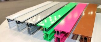
- Pencil (or marker). Used for workpieces made of aluminum alloys so that the scriber does not destroy the passivated protective layer.
- Accurate. It is done using the same methods, but special precision measuring and marking tools are used.
Techniques for marking metal parts
The selection of techniques is carried out in accordance with design and technological instructions.
What is metal marking - Metalworker's Handbook
Before you start processing a workpiece made of thin sheet metal, it should be marked , i.e. apply the contours of the future product to the workpiece.
Both slate and chalk lines are easily erased from the surface of metal, unlike wood. To prevent the marking lines from being erased, the metal surface can be pre-painted.
In this case, you can use a traditional marking tool - a pencil. But such a marking process will be lengthy and inconvenient.
There is the simplest and most widespread way - using a scriber.
Also, the following tools are used for marking:
Marking is one of the important and responsible operations. The quality of the future product depends on the accuracy of its implementation. If the workpiece is marked incorrectly, then in the future the cutting of the workpiece will not be according to size. This is especially important in the manufacture of volumetric products, where further work depends on the quality of correctly cut boundaries.
Before marking, the workpiece is straightened and cleaned of dust, dirt and traces of rust.
First, at a distance of approximately 5-8 mm from the edge of the workpiece, a
base line is drawn along a ruler using a scriber. Further construction is carried out from the base line.
The lines drawn during marking are called marks. Risks are main and auxiliary. The main risks indicate the processing boundaries. From the auxiliary marks, the dimensions for drawing the main marks are set aside. It is not difficult to draw precise lines with a scriber.
When applying straight marks, the ruler or square must be pressed tightly against the workpiece so that there is no gap.
When making a mark, take the scriber like a pencil and, without interrupting the movement, draw a mark of the required length. The sharp end of the scriber should be pressed against the ruler, and the scriber should be tilted away from the ruler. And the angle of inclination should not be changed, otherwise the line will turn out to be crooked and not parallel to the ruler.
You cannot draw a line twice, because... It's hard to hit the same line a second time. As a result, the line may turn out to be double. If you are not satisfied with the quality of the applied mark, then you should clean it with sandpaper and carry out the operation again.
If it is necessary to mark several identical parts, then templates are used - sample plates with contours of the parts. Before marking the template, you need to attach it to the workpiece and check whether the entire template fits on the sheet.
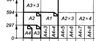
To use material economically, they try to find such a position for the template on the sheet so that when subsequently cutting blanks from the sheet, there will be as little waste and trimmings as possible.
After which the template is pressed tightly to the plane of the workpiece by hand or a clamp and outlined with a scriber.
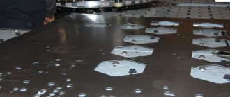
The centers of the holes are marked using a center punch. A core is placed in the marked center of the hole and a small hole (core) is made on the surface of the workpiece by lightly hitting the hammer with a hammer.
If it is necessary to mark a circle or rounding, then the leg of a marking compass, pre-set to the required radius of the circle, is installed in the resulting core, and the circle is outlined with the second leg.
- Before marking, it is necessary to check the serviceability of the marking tools.
- Perform marking only after editing the workpiece.
- Beware of sharp edges of sheet metal and wire.
- Do not put the scriber and marking compass in the pocket of your work coat.
- Pass the scribe only with the ring facing away from you.
Types and methods of processing various materials
Technologies for manual and machine processing of wood and wood materials. Technologies for manual and machine processing of metals and artificial materials
Page 3
Types and methods of processing various materials Areas of production. Professional career and education. Technologies of research and experimental activities. Housekeeping. Repair and construction work. Home Economics Topics.
Page 4
Since the beginning of February, work has resumed on creating a video blog on the “Bearded Trudovik” channel.
October 7 and 8 for grades 5-6 on the Olympic portal olymp74.ru October 7 and 8 for grades 7-8 on the Olympic portal olymp74.ru (round 1 - theory) Don't forget to take part!
I congratulate everyone on the beginning of the new school year and remind you to maintain discipline in the school workshop: Enter the workshop with the permission of the teacher. Place your bag with school supplies in the designated area. On the desktop, place only the school supplies necessary for the lesson Read more…
It is impossible to imagine a modern city without high-rise buildings. And our Lego city couldn’t do without them. Students in grades 5-7 during their technology lessons, divided into teams, tried to build the tallest tower. In addition to the height of the tower, its aesthetics and stability were taken into account Read more…
The theme for creative warm-up was “transport”. Some options are quite interesting. But there are also models that are distinguished by their simplicity and reliability. There were some unexpected decisions. One of the types of transport is not transport at all, but a coastal police post. But we are for Read more…
Pupils of 6G received the task “City landscape” for the lesson. What came out of this - look at the photographs.
Assembling Lego cars is much more interesting than sorting the construction set. But 7A found a way out and combined business with pleasure. First, a car repair shop was organized, then a transport exhibition. And only then - sorting. But everything worked out. Special thanks to Evgeniy and Sanjar for Read more…
So, the Lego city project is bringing its first results.
In the near future we will begin updating the exhibition in the aquarium. 80 plastic containers of different types were purchased specifically for storing parts Read more…
The Lego City project began its existence. In order to attract attention, the first, trial copy is displayed in the hall of the first floor. We invite everyone to join our project. If you have a Lego set that you haven’t played for a long time, or it’s lying around Read more…
The impromptu vacation in the form of a two-week quarantine is over. Work in the workshops has begun. Our immediate plans include opening a Lego exhibition and collecting Lego parts for the construction of a large Lego city. From February 29, as part of the school technology week (from February 29 to 5 Read more…
Marking of metal products
In the production of metal products, the source material - castings, sheet and profile products - does not correspond in size and shape to the designer's drawing.
To cut off excess metal, drill, stamp, weld, or otherwise process a workpiece, key points of the drawing are applied to it.
Applying to these points and lines, the processing is carried out.
Marking of metal products