Circle. Circle. Techniques for working with a compass, using stencils
Goals and objectives:
- Define circle, circle.
- Learn to divide a circle into equal parts.
- Learn how to perform geometric constructions using compasses and stencils.
- To familiarize yourself with the use of these geometric constructions in various fields of human activity.
- Cultivate patience and accuracy when performing tasks.
Lesson type: combined.
Forms of work : individual, group.
Compasses - a tool for drawing and marking
What a compass is is learned in mathematics lessons in elementary school, and acquaintance with this instrument continues in drawing and geometry. In the lives of technical students and industrial designers, more complex options appear: a compass with two needles and a caliper. In addition to these, there are many types of devices called “compasses”; the article describes the most commonly used ones.
Progress of the lesson:
Organizing time:
Checking readiness for the lesson.
Repetition:
Analysis of a graphical exercise.
New material:
Category “This is interesting!”
Since time immemorial, man has used the simplest geometric constructions in his life. One of these constructions is dividing a circle into equal parts. There are many examples that can be given. The transformation of a wheel from a solid disk into a rim with spokes presented man with the need to distribute the spokes evenly in the wheel.
The construction of regular polygons is inextricably linked with the division of a circle. Regular polygons are found in the most ancient ornaments of all nations.
In the decorative and applied arts, designers, jewelers and representatives of many other professions successfully used the division of the circle, creating beautiful works. These are orders, medals, coins and jewelry.
Order of the Red Star Order of the Patriotic War
The most common example of using dividing a circle into equal parts is the creation of logos, emblems, and trademarks of various companies. Sometimes it is enough to see the emblem on the hood or fender of a car and unmistakably identify the brand.
Showing visual aids of the use of geometric structures in construction, architecture, mechanical engineering, as well as natural phenomena.
Construction of a circle, circle.
A circle is a part of a plane bounded by a circle.
A circle is a closed plane curve, all points of which are equidistant from the center.
To draw a circle, just take a saucer or plate and circle it.
To construct a circle you need to find the center. Draw a circle from the center using a compass.
Construction stages:
- Draw a square.
- Divide the sides of the square into two equal parts, mark them with letters or numbers.
- Draw a center line (dash-dotted) through the resulting points. First horizontal, then vertical.
- Mark the intersection of the lines with a point O - the center of the circle.
- at point O and draw a circle. The center of a circle is also the center of a circle.
Remember: the strokes drawn by the center (axial) lines, and not the points, must intersect in the center. In circles of smaller sizes, it is allowed to draw thin construction lines instead of dash-dot lines.
Stencils are used to construct circles and circles.
Demonstration, display.
Dividing a circle into equal parts.
Any straight line drawn through the center of a circle divides this circle into two equal parts. Two mutually perpendicular lines drawn through the center of a circle divide this circle into 4 equal parts.
The circle can be divided into 8 equal parts using a ruler or squares.
Demonstration, display.
If we combine the points of the circle obtained by dividing, we get regular polygons.
When dividing a circle into 3, 6, 12 equal parts, not only squares are used, but also compasses. As a result of the construction, you can see a regular equilateral triangle, a regular hexagon (Figure 5)
Demonstration, display.
Physical education break.
Fastening:
Fragment from the workbook.
Prepare for work a compass, a pencil marked T and TM, a ruler, a stencil. Perform all constructions carefully.
Using a stencil with circles, draw a circle.
To construct a circle, you need to draw dash-dot lines. These lines consist of a stroke and a dot. When they intersect, they form the center of the circle and are the center or axial lines.
Place the leg of the compass at the center of the intersection of the axial (center) lines and draw a circle.
Stages of constructing a circle:
- Draw a square.
- Divide all sides of the square into two equal parts and mark the resulting points.
- Draw a center line (dash-dotted) through the points with a pencil marked T. First horizontal, then vertical.
- Mark the intersection of the lines with a point O - the center of the circle.
- at point O and draw a circle.
The center of a circle is also the center of a circle.
Remember: In the center, the strokes drawn by the center (axial) lines, and not the points, must intersect. In circles of smaller sizes, it is allowed to draw thin construction lines instead of dash-dot lines.
Rubric “REMEMBER”: circle, circle, center line, center line, dashed line.
Using compasses in geometry
No one thinks long about the answer to the question of what a compass is for. This subject is familiar even to primary schoolchildren. The main purpose of a compass is to draw circles of various sizes. Older schoolchildren already know that compasses not only draw circles, but also solve many different geometric problems.
For example, dividing a segment into two equal parts without drawing tools is very difficult. Using a compass, you can divide a segment into two parts that are absolutely equal in length. As you can see, for such an operation it is necessary to make the points indicating the ends of the segment the centers of intersecting circles. Draw a line through the intersection points of these circles along the chord. The intersection point of the line and a given segment will divide this segment exactly in half.
Here's another example of what a compass is for. Let's say you have given the sides of a triangle that needs to be constructed on paper. It is impossible to determine by eye the correct angles that such a triangle will have. Using a compass to construct a figure is very easy. Take a segment equal to one of the sides of the triangle. From the ends of the segment we draw circles, the radius of each of which is equal to the given length of the side of the triangle. The intersections of the circles will become the angles of the triangle we need.
Now you have an idea of what a compass is for. The pictures above illustrate its use.
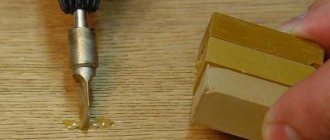
How to draw with a compass correctly
A very simple way to obtain a round element - instead of a compass, use a paper clip
One, two or three paper clips connected to each other will help us draw three circles with different radii. The project is useful for children if they want to quickly draw a circle with diameters of about 4, 9 and 15 cm (diameter depends on the type and size of paper clips). You will not achieve high accuracy, but the shape will be respected. A good experience for those who like a non-standard approach. Working with the simultaneous interaction of several felt-tip pens (pencils) and paper clips develops children's manual dexterity.
Materials:
Progress:
It’s easier, of course, to draw a circle by circling a round object - a cup, plate, coin, etc. But there is also a non-standard method that schoolchildren should learn about.
So, place a paper clip in the center of the sheet. Take a felt-tip pen and place it vertically on the paper. The tip should touch the edge of the paperclip, and another felt-tip pen should be inserted on the other side of the paperclip. You will hold one felt-tip pen motionless, and rotate the other along with the paper clip, without changing the radius of the circle. You can move in a circle in the direction that is convenient for you.
Now let's make the circle a little wider. To do this, you need to connect two or three paper clips, lay them comfortably on a plane, and then repeat the movement clockwise or counterclockwise.
If you want the center of the circle to be inconspicuous, use a sharpened pencil or quilling tool as in the project.
Drawing circles of various diameters is far from the most necessary skill in life. However, sooner or later the need to draw a circle without a compass and other round-shaped auxiliary objects takes everyone by surprise. Therefore, it is better to learn in advance how to draw a circle without a compass, regardless of its diameter.
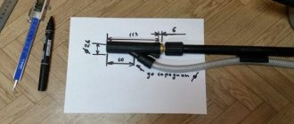
Structure
The device is quite simple, it has two parts connected to each other by a hinge. A needle is attached to the end of one leg, and a writing pencil or pen is attached to the other. Typically, the leads are sold as a set of preparations in a special case. If you have to select them yourself, you need to pay attention to the diameter of the writing rod. The latter must be tightly secured. The device, designed for measurements, has needles at both ends. High-quality professional tools are made of metal. For schoolchildren, stationery store workers can offer plastic or combined ones. The price of a school compass is much lower than that of a professional one. But it's not worth saving. The plastic wears out quickly, and a loose hinge has a bad effect on the quality of work.
How to draw an even circle without using a compass
You can be a schoolchild who came to a geometry lesson, forgetting his drawing tools, a student, an adult forced to draw a perfectly straight circle - different situations happen.
It will be useful for every person to know how to draw an even circle without a compass. We offer you several ways to solve this problem.
A compass can easily be replaced by another tool found in every student’s pencil case, namely a protractor. Place it on paper, marking the central point on the straight part, this will be the center of the future circle. Trace the inside of the semicircle, then rotate the ruler about ninety degrees and draw a third of the circle. Rotate the protractor one more time and complete the circle.
If you're in a meeting or at work and don't have the tool you need on hand, just use the CD. Trace it from the outside or from the inside to get a smaller shape.
In an office setting, you can also use a glass. To do this, take a glass of water, take a sip and place it on a sheet of paper, lightly circle the bottom. Drink some more and set it aside.
All of the above items can be found in any office; the protractor will also be available to students. With their help you can draw a circle evenly without a compass.
Description
The compass is made of metal and consists of two parts connected by a hinge. Usually at the end of one of them there is a needle, at the end of the other there is a writing object, for example a pencil lead, a pen, or a special holder for a rapidograph. A measuring compass has needles on both legs. A primitive compass is made of plastic.
A special set containing, in addition to the compass, additional accessories (such as replacement rods, needles) and tools (calipers, measuring compasses, drawing pen), as well as a case with corresponding recesses for them, is called a preparation kit.
Draw circles of different sizes without auxiliary objects
What to do if you need to draw circles of different diameters?
It is not at all difficult to cope with this problem, having only paper and a simple pencil on hand.
Take a pencil in one hand and place the other on a piece of paper. Place the little finger of your first hand on the sheet so that it is the center of the future circle. Hold this position well. With your other hand, start turning the paper around your little finger. You will see how a smooth circle is obtained, just like when using a compass.
A larger circle is drawn in the same way, but in this case bend your little finger, as if you were clenching all your fingers into a fist. With your left hand, start turning the sheet until you see the resulting circle. It is advisable to use a pencil with a soft lead.
A circle with an even larger diameter can be drawn by repeating all the above tips, but now the right hand should touch the sheet with the protruding bone on the wrist.
These are the simplest methods on how to draw a circle without a compass. The most important thing in these methods is to learn to keep your right hand motionless (left if you are left-handed).
Variety of instruments
How the compass appeared, a brief summary of the legend of the invention, all this is described above. It is also said that its design has remained unchanged. But one cannot help but notice that many analogues of the classic compass have appeared. They are intended not only for drawing circles, but also for other purposes. For example, a marking compass: it is used to transfer linear markings. Or calipers. It is needed so that you can draw such small circles that can be 2 mm in diameter. If you need a drawing made in ink, the lead can be easily replaced with a drawing pen.
Vernier calipers - for measuring circles of different diameters. To measure the scale on a map, you will need a proportional compass. Cartographers, navigators, navigators - everyone uses this unique tool. There is also an instrument called “Sturmansky”.
How to Draw a Perfect Circle Using a Ruler
If you have a regular ruler on hand, then you can use another tip on how to draw a circle without a compass. Take a ruler and place it on the paper, the “0” mark will be the center of the circle, so place it in the right place. Draw the second point near the digital value corresponding to the radius of the circle. Move the second edge of the ruler slightly so that the middle remains at zero, and the third point is located slightly above the second.
Do this procedure several times. As a result, you should have a circle drawn with a dotted line. The more often the dotted line, the easier it will be to connect everything into a solid line.
This is perhaps the easiest, but at the same time the longest way to draw a circle without a compass.
Popular
Drawing Basics
Construction
Mechanical Engineering
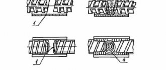
Construction of a regular hexagon inscribed in a circle. The construction of a hexagon is based on the fact that its side is equal to the radius of the circumscribed circle. Therefore, to construct it, it is enough to divide the circle into six equal parts and connect the found points to each other (Fig. 60, a).
A regular hexagon can be built using a straight edge and a 30X60° square. To carry out this construction, we take the horizontal diameter of the circle as the bisector of angles 1 and 4 (Fig. 60, b), construct sides 1-6, 4-3, 4-5 and 7-2, after which we draw sides 5-6 and 3- 2.
Construction of an equilateral triangle inscribed in a circle . The vertices of such a triangle can be constructed using a compass and a square with angles of 30 and 60° or just one compass.
Let's consider two ways to construct an equilateral triangle inscribed in a circle.
The first method (Fig. 61,a) is based on the fact that all three angles of the triangle 7, 2, 3 contain 60°, and the vertical line drawn through point 7 is both the height and the bisector of angle 1. Since angle 0— 1-2 is equal to 30°, then to find the side
1-2, it is enough to construct an angle of 30° from point 1 and side 0-1. To do this, install the crossbar and square as shown in the figure, draw line 1-2, which will be one of the sides of the desired triangle. To construct side 2-3, set the crossbar in the position shown by the dashed lines, and draw a straight line through point 2, which will determine the third vertex of the triangle.
The second method is based on the fact that if you build a regular hexagon inscribed in a circle and then connect its vertices through one, you will get an equilateral triangle.
To construct a triangle (Fig. 61, b), we mark a vertex on the diameter - point 1 and draw a diametrical line 1-4. Next, from point 4 with a radius equal to D/2, we describe an arc until it intersects with the circle at points 3 and 2. The resulting points will be the other two vertices of the desired triangle.
Constructing a square inscribed in a circle . This construction can be done using a square and a compass.
The first method is based on the fact that the diagonals of the square intersect in the center of the circumscribed circle and are inclined to its axes at an angle of 45°. Based on this, we install the crossbar and square with angles of 45° as shown in Fig. 62, a, and mark points 1 and 3. Next, through these points we draw the horizontal sides of the square 4-1 and 3-2 using a crossbar. Then, using a crossbar along the side of the square, we draw the vertical sides of the square 1-2 and 4-3.
The second method is based on the fact that the vertices of the square bisect the arcs of the circle enclosed between the ends of the diameter (Fig. 62, b). We mark points A, B and C at the ends of two mutually perpendicular diameters and from them with a radius y we describe arcs until they intersect each other.
Next, through the intersection points of the arcs we draw auxiliary straight lines, marked in the figure with solid lines. The points of their intersection with the circle will determine vertices 1 and 3; 4 and 2. We connect the vertices of the desired square obtained in this way in series with each other.
Construction of a regular pentagon inscribed in a circle.
To fit a regular pentagon into a circle (Fig. 63), we make the following constructions.
We mark point 1 on the circle and take it as one of the vertices of the pentagon. We divide the segment AO in half. To do this, we describe an arc from point A with the radius AO until it intersects with the circle at points M and B. By connecting these points with a straight line, we get point K, which we then connect to point 1. With a radius equal to the segment A7, we describe an arc from point K until it intersects with the diametrical line AO at point H. By connecting point 1 with point H, we get the side of the pentagon. Then, using a compass solution equal to the segment 1H, describing an arc from vertex 1 to the intersection with the circle, we find vertices 2 and 5. Having made notches from vertices 2 and 5 with the same compass solution, we obtain the remaining vertices 3 and 4. We connect the found points sequentially with each other.
Constructing a regular pentagon along a given side.
To construct a regular pentagon along a given side (Fig. 64), we divide the segment AB into six equal parts. From points A and B with radius AB we describe arcs, the intersection of which will give point K. Through this point and division 3 on line AB we draw a vertical line.
Next, from point K on this straight line we lay off a segment equal to 4/6 AB.
We get point 1—the vertex of the pentagon. Then, with a radius equal to AB, from point 1 we describe an arc until it intersects with the arcs previously drawn from points A and B. The intersection points of the arcs determine the pentagon vertices 2 and 5. We connect the found vertices in series with each other.
Construction of a regular heptagon inscribed in a circle.
Let a circle of diameter D be given; you need to fit a regular heptagon into it (Fig. 65). Divide the vertical diameter of the circle into seven equal parts. From point 7 with a radius equal to the diameter of circle D, we describe an arc until it intersects with the continuation of the horizontal diameter at point F. We call point F the pole of the polygon. Taking point VII as one of the vertices of the heptagon, we draw rays from the pole F through even divisions of the vertical diameter, the intersection of which with the circle will determine the vertices VI, V and IV of the heptagon. To obtain vertices / - // - /// from points IV, V and VI, draw horizontal lines until they intersect with the circle. We connect the found vertices sequentially to each other. A heptagon can be constructed by drawing rays from the F pole and through odd divisions of the vertical diameter.
Determination of readings by vernier
To determine the readings of a caliper, it is necessary to add the values of its main and auxiliary scales.
- The number of whole millimeters is counted on the bar scale from left to right. The pointer is the zero stroke of the vernier.
- To count fractions of a millimeter, it is necessary to find the vernier stroke that most accurately matches one of the strokes of the main scale. After this, you need to multiply the serial number of the found vernier stroke (not counting zero) by the value of its scale division.
The measurement result is equal to the sum of two quantities: the number of whole millimeters and fractions of mm. If the zero line of the vernier exactly coincides with one of the lines of the main scale, the resulting size is expressed as an integer.
The figure above shows the readings of the ShTs-1 caliper. In the first case they are: 3 + 0.3 = 3.3 mm, and in the second - 36 + 0.8 = 36.8 mm.
Vernier with 0.05 mm division
The instrument scale with a division value of 0.05 mm is presented below. For example, two different indications are given. The first is 6 mm + 0.45 mm = 6.45 mm, the second is 1 mm + 0.65 mm = 1.65 mm.
Similar to the first example, you need to find the strokes of the vernier and the rod that exactly match each other. In the figure they are highlighted in green and black, respectively.
Mechanical caliper device
The design of a double-sided caliper with a depth gauge is shown in the figure. The measurement range of this instrument is 0-150 mm. With its help, you can measure both external and internal dimensions, the depth of holes with an accuracy of 0.05 mm.
Essential elements
- Barbell.
- Frame.
- Sponges for external measurements.
- Sponges for internal measurements.
- Depth gauge ruler.
- Locking screw for fixing the frame.
- Vernier scale. Serves to count fractions of millimeters.
- Bar scale.
The jaws for internal measurements 4 are knife-shaped. Thanks to this, the hole size is determined on a scale without additional calculations. If the caliper jaws are stepped, as in the ShTs-2 device, then when measuring grooves and holes, their total thickness must be added to the readings obtained.
The reading value of the vernier may differ for different instrument models. So, for example, for ShTs-1 it is 0.1 mm, for ShTs-II it is 0.05 or 0.1 mm, and the accuracy of devices with a vernier reading value of 0.02 mm approaches the accuracy of micrometers. Design differences in the design of calipers can be expressed in the shape of a moving frame, measurement ranges, for example: 0–125 mm, 0–500 mm, 500–1600 mm, 800–2000 mm, etc. The accuracy of measurements depends on various factors: the reading value on the vernier, work skills, and the good condition of the instrument.
Caliper models by functionality
A drawing tool is used to depict circles of small diameter (from 0.5 to 80 millimeters). It is designed as follows: inside a cylindrical sleeve there is a steel rod, it can move freely up and down, as well as rotate. A cap is attached to one end of the rod, and a sharp needle is attached to the other end. A tool for drawing lines - a drawing board - is attached to the sleeve using a plate that can be bent at different angles. Depending on the model, stylus, ink or ink can be used for drawing. The micrometric screw is used to reduce or increase the distance between the drawing board and the rod.
READ Where is a file used?
The screw removes or brings the plate closer to the cylindrical sleeve, as a result the diameter of the circle changes down to the smallest (up to 0.5 millimeters).
The measuring version of the caliper is used to calculate the outer lengths of parts and components of mechanisms, as well as to compare their sizes with the reference ones (taken from a scale ruler). But not only such an indicator as length is measured using this device. It can also measure other machine parameters, such as the diameter of parts. This instrument, as a measuring device, does not need verification, because it is not included in the state register. To compare the dimensions of parts of an object with standard dimensions, this type of caliper is used. So, having measured a part using such a specific method, the data obtained is compared with the data of the samples, from which conclusions are drawn.
Exemplary (reference) dimensions can be represented by a scale ruler (a reference sample that is used to compare sizes on a given scale), gauge blocks (a ceramic or metal board with measuring planes from 0.5 to 1000 millimeters) or gauges (a predetermined size parts, details).
The marking model is used to divide plans in cartography, lines, and other things into segments. This instrument is designed in such a way that, with the help of a micrometer screw, the amount of solution taken is kept motionless for as long as desired. The solution is the distance from one caliper leg to the other when they are spread apart. By the way, solution is a concept characteristic not only of compasses. The solution also occurs on the blades of scissors and other instruments that have ends that move apart. The maximum permissible value of the solution is the maximum distance between the legs; it depends on the length of the screw, but in general, a micrometric screw, as its name implies, does not allow for a large diameter. To measure longer distances, a different instrument is required.
The procedure for carrying out measurements, checking serviceability
Before work, check the technical condition of the caliper and, if necessary, adjust it. If the device has warped jaws, it cannot be used. Nicks, corrosion and scratches on working surfaces are also not allowed. It is necessary that the ends of the rod and the depth gauge ruler coincide when the jaws are aligned. The instrument scale must be clean and easily readable.
- The caliper jaws are pressed tightly against the part with little force, without gaps or distortions.
- When determining the outer diameter of a cylinder (shaft, bolt, etc.), make sure that the plane of the frame is perpendicular to its axis.
- When measuring cylindrical holes, the jaws of the caliper are placed at diametrically opposite points, which can be found by focusing on the maximum scale readings. In this case, the plane of the frame must pass through the axis of the hole, i.e. Measurement along the chord or at an angle to the axis is not allowed.
- To measure the depth of a hole, a rod is placed at its edge perpendicular to the surface of the part. The depth gauge ruler is pushed all the way to the bottom using a movable frame.
- The resulting size is fixed with a locking screw and the readings are determined.
When working with a caliper, monitor the smooth movement of the frame. It should sit tightly on the bar without swaying, while moving without jerking with moderate force, which is regulated by the locking screw. It is necessary that when the jaws are aligned, the zero stroke of the vernier coincides with the zero stroke of the rod. Otherwise, reinstallation of the vernier is required, for which the screws securing it to the frame are loosened, the strokes are aligned and the screws are re-fastened.
Measuring
They are used to perform various turning and metalworking works. In addition, they are often used by blacksmiths and coopers. With its help, you can get ahead of whether the part is actually made in the desired shape. For this purpose, it is necessary to measure the diameter at two points. If the device rotates freely around the entire perimeter of the circle (there are no gaps and there is no need to squeeze the legs), then the circle has an ideal shape. In addition, such calipers are used to determine the internal dimensions of the workpiece. For example, you can find out the width of the grooves. Another use of the device is to compare the dimensions of objects. Having taken measurements of the reference part, you can compare the obtained values with the dimensions of other workpieces, which significantly speeds up the work. The main advantage of such devices is their small measurement error. Such models can be of two types. They differ in the shape of the tips of the legs. If the outer side of the tips has a flat sharpening, then such devices are used to determine the internal dimensions. External dimensions are measured with tools that have a flat surface on the inside.
How to use a caliper: step-by-step instructions
Vernier calipers are used to determine outer and inner diameters, linear dimensions, depths of grooves and holes, and distances between shoulders. Some modifications allow markings to be applied to the surfaces of workpieces. The tool is used to measure workpieces in mechanical and metalworking production areas, to control the production of wear surfaces when repairing equipment, and due to its ease of use, it is used in home workshops.
Application
Compasses are used in many areas of human activity.
- For drawing. The method that is taught in school. Carrying out a drawing “by hand” without using computer programs requires the mandatory use of a compass. In addition to circles, this tool is used to draw various arcs, mates, and perform additional constructions and markings.
- For measuring. Calipers measure the dimensions of parts, internal diameters, and hole depths. Measuring compasses are used in navigation and cartography. This tool has found its application not only in engineering, design, and geodesy. Thick compasses are used in medicine to measure the transverse dimensions of the human body.
A compass, like a pencil, is needed by every self-respecting geologist, cartographer, sea captain, surveyor, mathematician, architect, and builder.
In spiritual practices and philosophy, the compass began to symbolize unwavering and impartial justice. Many professions and areas of human activity are associated with drawings, their construction, reading, reproduction, and in all these professions a device with a four-thousand-year history is necessary.
Source
Vernier caliper design
Shown in Fig. 1 caliper type ШЦ-1 consists of:
- Barbells.
- Framework.
- Measuring scale.
- Upper lips.
- Lower lips.
- Depth gauge.
- Vernier scales.
- Clamping screw.
The choice of caliper for a specific task is determined by the dimensions, design features of the part and requirements for dimensional accuracy. The tools differ in the following parameters:
- Measuring range . The length of the scale on the rod ranges from 125 to 4000 mm.
- Accuracy . Common modifications have an error of 0.1, 0.05, 0.02 and 0.01 mm.
- Functionality . There are calipers with and without a depth gauge.
- The number and shape of measuring surfaces. The jaws of single-ended and double-ended instruments are available in flat, pointed or rounded shapes.
- The design of the reading device . It can be vernier, mechanical, clock type or electronic.
Vernier calipers are made of wear-resistant tool steels, and their measuring surfaces can be reinforced with carbide tips. To mark parts, cutters are installed on non-sharpened jaws (Fig. 2), complete with holders and clamping screws.
Measurement order
The tool and part need to be prepared for work: remove dirt, bring the jaws together and make sure that the readings correspond to “0”. To measure the outer diameter or linear dimension you must:
- spread the sponges by moving the frame;
- move until it fits snugly against the countersurfaces;
- fix the position of the frame with a locking screw;
- bring out a caliper to evaluate the results obtained.
To measure the internal size, the jaws are brought to “0” and then moved apart until they come into contact with the countersurfaces. If the design features of the part allow you to see the scale, then the readings are read without fixing or removing them.
To measure hole depth:
- by moving the frame, the depth gauge is extended;
- lower it into the hole to the bottom and press it against the wall;
- move the bar until it stops at the end;
- fix with a locking screw and remove.
The accuracy of the results depends on the correct positioning of the jaws relative to the part. For example, when determining the diameter of a cylinder, the rod must intersect or cross with its longitudinal axis at a right angle, and when measuring the length, it must be positioned parallel. In calipers of the ShTs-2 and ShTs-3 types there is an additional frame, which is movably connected to the main micrometric adjusting screw (Fig. 3). This design simplifies tool positioning. When taking measurements, the additional frame is fixed on the rod, and the position of the main frame is adjusted by rotating the micrometer screw.
Types of compasses
There are many types of compasses. Depending on the functions performed, the working part of the tool changes. Below we consider the main types:
- Marking. Either dividing or measuring. A simple tool with which you can measure the length and transfer it from the drawing to the part. Both rods are connected by a hinge and end with needles. Using needles, you can mark many materials.
- Drawing. The instrument that people begin to use in school. There is a needle on one rod, a stylus on the other. The needle fixes the barbell on a sheet of paper, allowing you to draw arcs and circles and perform constructions.
- Calipers for external measurements. Its pointed rods are bent inward, and the part to be measured is clamped between them. A fixing screw is used to improve accuracy.
- Calipers for internal measurements. The rods are bent outward at the ends. Allowing you to measure the width of holes, recesses, grooves.
- Calipers. It has a structure that is different from the usual one. It is a ruler (bar) with a scale. One jaw is fixedly attached to one end of the ruler, and the second one moves along the ruler. There are also additional small jaws for internal measurements. The tool is used both as a bore gauge and as a caliper.
- Vernier depth gauge. Looks like a caliper. The difference is that it is intended to determine the depths of holes, grooves, and grooves. To take measurements, the working part is placed inside the hole until it stops.
There are types of tools, modified depending on the activities in which they are used, for example:
- Carpentry. It can be marking, that is, with needles at the ends of the rods, or it can be drawing, with a stylus on one rod and a needle on the other. It differs from the drawing ones primarily in size. These are quite large instruments.
- Locksmith. Used in plumbing. They can also be marking or with a writing tip.
Reading results
Vernier scale
The number of whole millimeters is counted from the zero division on the staff to the zero division of the vernier. If they do not match, then the size contains fractions of a millimeter corresponding to the accuracy of the tool. To determine them, you need to count on the vernier from zero to the line that coincides with the mark on the bar, and then multiply their number by the division value.
Figure 4 shows the dimensions: a – 0.4 mm, b – 6.9 mm, c – 34.3 mm. Vernier division value 0.1 mm
By hourly indicator
The number of whole millimeters is counted on the bar from zero to the last mark not hidden under the frame. Shares are determined by an indicator: the number of the division on which the arrow stops is multiplied by its price.
Figure 5 shows the size 30.25 mm. The indicator division value is 0.01 mm.
By digital display
There is no need to count here, the size is shown on the display.
To determine the internal size taken with a tool with radius measuring surfaces (lower jaws in Fig. 3), their thickness, which is indicated on the fixed jaw, is added to the readings on the scale. To calculate the outer size taken with a caliper with cutters (Fig. 2), their thickness is subtracted from the readings on the scale.
Device
The drawing tool that we are all accustomed to consists of five main parts:
- Holder. Simple models are made of plastic, professional ones are made of corrugated steel. The compass is held by it during operation; notches or non-slip material allow you to firmly hold the tool in your hand. In modern models, the holder is ergonomic and user-friendly.
- Rods are the basis of the tool. In order to minimize errors when drawing arcs and circles, they are made from alloys of increased rigidity. In compasses intended for schoolchildren, galvanized or plastic rods are used, because the task of such a tool is not an accurate drawing, but learning to work with it.
There are models that have additional fixation of the rods in a certain position using a lever with a hinge or a screw fastening.
- Attachment of rods. In products for professionals, each rod has grooves for mounting fasteners. Usually the mount is covered with a decorative plastic cover. A new high-quality tool can be distinguished by the tight movement of the rods, since it has a rigid and therefore reliable fastening. The plastic mount is unreliable and will not allow you to make an accurate drawing.
- Needle. The basis of an accurate drawing. In models for children, the needle is blunted, such a device is less accurate, but safety comes first! In serious instruments the needle is sharp. Its length may vary. Needles are long and short, from 3 to 9 mm, depending on the model. The more professional the product, the longer the needle and the possibility of replacing it. There are double-sided needles.
The needle is either welded to the rod (simple training) or attached to a special holding device (professional).
- Nozzles A very important detail. There are three types of nozzles:
- Nozzle with a stylus with a diameter of 2 mm. Used by professionals.
- Nozzle with universal holder. The drawing tool in it can be a simple pencil. This attachment was nicknamed the “goat leg”.
- Mechanical pencil attachment. The thickness of the lead here is 0.5 mm.
The design of the compass has not changed for centuries, its main parts are constant, only the materials from which they are made are changeable.
Marking
A regular caliper with pointed measuring surfaces copes with basic marking operations. By pressing one jaw against the side of the part, you can use the tip of the second to draw a line on the surface perpendicular to it. The line turns out to be equidistant from the end and copies its shape. To draw a hole, you need to mark its center: the recess serves to fix one of the jaws. Any technique of descriptive geometry can be used in a similar way.
Carbide tips and cutters leave noticeable scratches on parts made of steels with a hardness above 60 HRC. There are also narrow-profile calipers designed exclusively for marking.
Why do measurement errors occur?
The most common errors that reduce the accuracy of measurement results with a working instrument:
- Excessive pressure on the frame causes misalignment relative to the rod. The same effect is obtained if, when measuring with the lower jaws, the caliper is brought together by the upper jaws.
- Installation of jaws on fillets, chamfers and roundings.
- Distortions during positioning.
- Instrument calibration violation.
The first three mistakes most often arise from lack of experience, and go away with practice. The latter must be prevented at the stage of preparation for measurements. The easiest way is to set “0” on an electronic caliper: there is a button for this (in Fig. 6 the “ZERO” button). The hour indicator is reset by rotating the screw located at its bottom. To calibrate the vernier, loosen the screws securing it to the frame, move it to the desired position and fix it again.
Deformation of the caliper elements and wear of the measuring surfaces make the tool unsuitable for use. To reduce the number of defects in production, calipers undergo periodic verification by metrological services. To check the accuracy of a tool and acquire skills at home, you can measure parts whose dimensions are known in advance: for example, drill shanks or bearing rings.
Presentation on technology for primary school “Learning to work with a compass”
Description of the development
What do you think this is about?
Its name has something from “circus”, and it itself resembles a circus performer: its legs are long, look like stilts, and its head is small. He doesn’t walk, but writes, or rather, draws a variety of circles with his foot: large, smaller, and small circles.
From the history of compasses.
It has been used for many centuries by schoolchildren, scientists, engineers, and draftsmen, because the compass is one of the most ancient tools on Earth.
The oldest compass lay for two thousand years in an ancient mound in France. French archaeologists did not rack their brains for a minute over the question of what kind of object this was, because the compass from ancient times to ours has remained almost the same.
The Romans had iron and bronze compasses Many of them were found in the ashes that covered the city of Pompeii. Apparently, teachers in Italy always introduced schoolchildren to geometric figures and strictly punished them: “Don’t forget to bring a compass to class!”
This instrument also existed in Ancient Rus', because our ancestors loved to decorate many objects with patterns. Archaeologists found a steel compass during excavations in Novgorod.
The names “compass” and “circus” really have something in common.
It turns out that they both came from the same Latin word “circulus” - circle, circumference. That's right: the circus is the arena, the arena is the circle, and the circle is what the compass creates.
Using a measuring compass
Since ancient times, the compass has expanded its scope of application. For example, this instrument is found without a lead or pencil at all - it has sharp needles on both legs. One may ask, what is a compass without a lead used for? Any engineer will say that this is a measuring compass. It is not intended for drawing circles and ellipses, but is available in every kitchen. Why do you need a measuring compass? Using it, you can quickly and accurately measure equal distances in a drawing or mark a drawing using almost invisible scratches on the paper.
READ What is a circular saw and what is it used for?