08Dec
- By: Semantics
- Uncategorized
- Comments: 0
A variety of devices are used today for processing workpieces. Let us pay attention to perhaps the most popular of them - metal cutting devices: we will consider in detail the characteristics by which they are divided, and the scope of application of each of them, design features and main operating parameters. There are so many nuances - so that you understand which one to choose and use in each specific situation.
Separately, we note that they are not only still relevant, but they also remain promising. It is mechanical technology that remains in demand, largely due to its availability. The moment of unification also plays a role: the same drills and cutters are often suitable for entire series of machines and, with all their compatibility, can provide highly accurate results.
Classification of metal-cutting tools
There are a number of key parameters - let's take a look at each.
Based on the nature of processing (action), they are divided into:
- blade - cut off excess material;
- abrasive - abrade the surface, bringing it to the desired geometry by grinding.
By design they can be:
- solid - completely made from one piece;
- composite - made of several parts, all connections of which are permanent;
- prefabricated - their elements are fastened so that they are easy to separate if necessary.
According to the mounting option, there are top-mounted and tail-mounted ones. There are also options for drives (manual, machine or combined) and shape (plate, cylindrical, disk, conical), and each of them is in demand in its niche.
Classification of blade tools
According to the material of the working part
They are distinguished
by steel, high-speed cutting, carbide, mineral-ceramic and super-hard materials.
By number of blades:
single-
and
multi-blade tool.
Multi-blade tool
– the blades in space are located in the direction of the main movement sequentially.
According to the location of the teeth in space:
peripheral, end, peripheral-end.
According to the design of the blades:
Mechanical blades
– a prefabricated blade tool with a detachable connection to the body or knife.
With brazed plate
– a bladed tool, the blades of which are made by soldering a cutting plate onto a body or knife.
With glued plate
– connection with glue.
Fused Blade Tool
- a composite blade tool, the blades of which are made by surfacing tool material.
Tooth direction
–
straight, helical and helical.
Main types of metal-cutting tools
Depending on the purpose, the operations carried out with their help and the features of their execution, all devices are divided into a number of groups. Let's look at each one, paying attention to the key points.
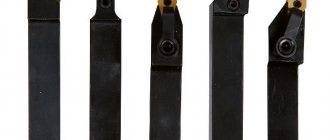
Incisors
There is a wide range of sizes, but each of them is single-edged and designed for processing all kinds of rotating bodies. And they all have the following configuration nuances:
- made with a holder and a working part;
- made of alloys that determine a specific material, and therefore the scope of their application;
- with a specific sharpening angle depending on the use cases.
They are also divided according to purpose - into the following options:
- cutting - for separating (some portion of the workpiece from the whole) at an angle of 90 0;
- through - straight, bent, persistent - for chamfering, including perpendicular to the axis of rotation;
- threaded - for creating turns from the inside or outside of parts;
- Boring – designed to expand blind or through holes.
In terms of their design, they can be either solid or prefabricated - with replaceable plates, providing versatility (but, unfortunately, reducing overall reliability and durability).
Depending on the side of fastening on the holder, cutters for lathes are divided into right and left. It’s quite easy to check which one you got. You just need to place the palm of the corresponding hand on it, with your fingers towards the top. The directions of the large and main edges should match - look at the diagram below:
Milling cutters
These are almost the most popular multi-blade cutting tools in mechanical engineering, made in the form of bodies of revolution and equipped with teeth on the working surfaces. Attention, they remove material from a fixed product. The design is more complex than the representatives of the previous group, therefore they are more expensive.
They are used to solve a wide range of problems: to give the desired geometry to the side and end planes (external), to bore holes to the required diameter, to make relatively complex shaped contours from a simple (rectangular) workpiece.
They are divided into groups according to several indicators:
- by the location of the teeth;
- according to the specifics of the edge;
- on the operations performed;
- on fastening nozzles;
- according to the material of manufacture.
The modern classification of cutting tools is very wide and varied, so we will focus on the most popular and in demand types of cutters. Using their example, one can form a correct impression of other similar devices. So, the most relevant are the following models:
End ones - needed to create contour recesses, ledges, deep grooves, smooth transitions when forming complex reliefs of body parts. They are similar in appearance to drills, but without edges at the bottom, and are often made with a conical shank, which ensures fastening rigidity.
Cylindrical - made like bushings with technological holes and grooves, due to which they are mounted on a mandrel. They have several blades at once, located along the axis, with an angle. They are used for high-precision grinding of individual sections of the workpiece; they can also be used for turning (if angular heads are installed on the spindle).
Disk - their shape is clear from the name; they are quite thin and act perpendicular to the direction of movement of the part, which allows making cuts from 1 mm. Based on the type of plates, these cutting tools for metal processing are divided into slotted, semicircular, three-sided, and modular.
Face - their edges are located at the bottom of the body, and this configuration allows you to maintain a high speed of turning the plane (the fixing table moves longitudinally); as a result, labor productivity is several times higher than with planing. They also have a cylindrical body, with a chuck, a shank and a key that transmits torque.
Worm - with shaped blades, sharpened in a reverse involute and located at a certain slope (depending on the area of application). Relevant for creating teeth on wheels, gears, and shafts. They operate on the rolling-in principle, when the workpiece is rotated with a fixed displacement step.
Corner and end - part of them is a truncated cone, and this shape allows you to quickly trim flat parts along the edge, providing a flat and smooth surface.
Saws - exclusively for cutting operations, for which their teeth are made sharp, often the same thickness as the body (in this case, they are made without transition). Attached using a groove connection. They are distinguished by economical cutting, especially in demand when processing shafts and technological profits.
Shaped - needed to give workpieces a complex and predetermined configuration (the geometry of their surface will be the opposite of the edge). Outwardly they look like files secured in cartridges by shanks.
Keyed - special, disk and finger at the same time, first acting like a drill, then with vertical working. Necessary for creating grooves.
Drills, countersinks, countersinks and reamers
The first devices of this group are well known to any person who has ever needed to make a hole in a hard surface. They are axial, they bite into the part due to the rotational movement, while the chips are removed along the helical grooves.
They differ from each other in such indicators as:
- execution material;
- shank;
- diameter (size);
- sharpening angle of the main edge.
The next popular cutting tool is a countersink, used either to widen a hole (increase the diameter) or to adjust it (increase accuracy). The conical entrance areas of the bolt seat are also machined using a special device called a countersink. Well, the roughness is reduced by a sweep - it won’t be difficult to bring the plane to the desired level of smoothness.
Broaches and firmware
The first ones have several blades at once, arranged sequentially and so that each new one protrudes above the previous one. This configuration makes it possible to remove material from the workpiece both in rotational and translational motion, and in static mode - at an angle of 90 0 to the feed direction.
They are considered professional equipment and are relatively expensive, but they have a number of advantages:
- the durability resource is high, and this is the key to low operating costs;
- During the work process, several teeth are involved at once, which allows you to increase the allowance and is a guarantee of impressive productivity;
- accuracy level – up to 6th grade inclusive;
- with their help you can effectively remove defects.
Firmware is a modern machine cutting tool that allows you to quickly make four- and hexagonal, slotted, TORX R and other holes.
If it is designed as a head, it is compatible with turning, milling, and CNC equipment, and is effective for both horizontal and vertical passes. Its supporting shaft is mounted at a given angle on ball bearings, so it successfully withstands even heavy loads. Deepening into the workpiece material occurs smoothly, so the required profile of the seat is created with high precision.
If it is aimed at creating internal holes, it is a rod with a cylindrical shank and a guide of the required cross-section. If it is used to pierce external seats, it has the opposite configuration - the desired profile is knocked out inside the disk, which is reproduced upon contact with the part.
The size range includes 7 positions, marked with the Latin letter G (from G5 to G25).
Gear cutting and grinding tools
Already from the name of the first it is clear why it is needed - to create clutch elements on splined rollers, ratchet and worm wheels and other similar parts. And its range is quite wide – it includes:
- finger and disk cutters – operate modularly;
- heads - form all the cavities simultaneously by copying (in several passes);
- combs - straight and helical, serve as planing incisors;
- cutters - wheels with edges that allow external/internal gearing.
This group also includes devices that work using the rolling method, that is, so that the edges, as a result of sliding, consistently create a surface of the required geometry.
Threading type cutting tool
It also has a “telling” name - it is needed to form helical lines of various sizes and patterns, which allow for a reliable connection. It boasts a wide range of products, including:
- heads, vortex or self-opening, made according to GOST 21760-76;
- tangential combs;
- lerks (dies);
- cutters, disk, end and others;
- taps, including nut and automatic taps, complying with interstate standards 1604-71, 3266-81, 6951-71, 8859-74.
These devices allow you to apply metric, inch, tapered, pipe cylindrical, left-handed and right-handed threads, even in through or blind holes.
Abrasive types
These are all kinds of wheels (grinding, grinding, etc.), cups, attachments used for machining parts.
The main characteristic of a cutting tool of this group is surface hardness, which must be stronger than the workpiece material in order to act on it, and not vice versa. Therefore, it is made from grains of electrocorundum, synthetic and natural diamonds, silicon carbide, randomly combined into bonds (bakelite, silicate, ceramic, magnesia, vulcanite, hyphthalic). Due to this, it acquires the ability to self-sharpen: by chipping and dulling, the upper particles make room for new layers.
All of the listed device options are rigid, but there is also a flexible category, which includes tapes and disks.
Hand-held metal-cutting tool
This is a portable alternative to machine tools - devices that facilitate human labor, and examples include:
- profile or nibblers – used to separate part of rolled sheet metal from the whole workpiece;
- panel cutters – needed for working with sandwich panels, ensuring speed and accuracy of operations;
- folding machines - allow you to automate the process of closing recumbent joints;
- molders – necessary for proper compression of rolled products;
- mobile pliers - very convenient for cold welding, they help to press the elements to be joined with great force.
Important criteria for classifying metal cutting tools
There are 3 most important criteria for classifying cutting tools for metal machines.
- Purpose.
- Design.
- Mounting method.
Let's move on to the details.
Options for metal cutting tools
Based on their design, metal cutting tools are divided into 3 groups.
- Solid. They are single products. They are made from tool, alloy and high-speed steels, as well as hard alloys using casting technology. They are distinguished by their reliability and low cost (if you do not take into account carbide devices).
- Composite. Working parts are manufactured using materials of the highest quality with the required characteristics. The cutting surfaces of metal tools are improved using welding and soldering technologies. One-piece devices are obtained. They are more expensive than models of the first type.
Photo No. 3: compound cutting tools for metal
- Prefabricated. The main parts and parts in contact with the workpieces of such metal cutting tools are separate products. They are connected mechanically. This design makes it possible to quickly replace working parts when worn out. Metal cutting tools in this category are more expensive than their analogues.
Photo No. 4: prefabricated metal cutting tools with removable carbide inserts
Basic operations performed using metal cutting tools
Various technological operations are performed on machines using metal cutting tools. The most important groups into which devices are divided according to purpose are 6.
1. Metal cutting tools for cutting threads. The most commonly used tools for these operations are taps, dies and rollers.
They are used in the manufacture of various fasteners and connecting parts of parts. Using taps, internal threads are cut, and external threads are cut using dies.
Photo No. 5: machine with a die installed
2. Metal cutting tools for the manufacture of gears. These are dolbyaki and shavers.
Devices of the first type are used in the manufacture of:
- helical and spur gears, as well as models with protruding flanges;
- chevron gears with and without grooves;
- gear racks and sides;
- other gear parts with external and internal gearing.
Shapers are also used to produce splined holes in gears and shafts, as well as grooves, corners and grooves on shaped and flat surfaces.
Photo No. 6: dolbyaki
The purpose of the shaver is the special finishing of gears. Its name is shaving. When processing parts, excess layers of chips are removed from the surfaces of the teeth. The principle of shaving is the discrepancy between the angles of inclination of the teeth of the wheels and shavers during sliding during running-in.
Photo #7: shever
3. Metal cutting tools for grinding the surfaces of products and workpieces. Most often, abrasive wheels with different grain sizes are used for this. Fine-grained tools are used for finishing, while coarse-grained tools are used for roughing operations.
Photo No. 8: diamond abrasive wheel for metal
Parts are processed on belt grinding machines using abrasive belts.
Photo No. 9: grinding machine with abrasive belt installed
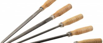
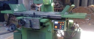
4. Metal cutting tools for processing and obtaining various surfaces, corners, grooves, grooves and ledges. Most often, milling machines are used for this. They are equipped with cutters of various types.
Photo No. 10: metal cutters
5. Metal cutting tools for producing and processing through and blind holes. The main devices of this group include drills, countersinks, reamers, counterbores, etc.
For example, reamers are used to increase the accuracy and reduce the roughness of holes produced using drilling technology.
Photo No. 11: metal reamers
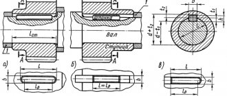
6. Metal cutting tools for processing bodies of rotation. In most cases, it is performed using incisors. With their help, the following technological operations are performed.
- Turning workpieces along the axes of rotation.
- Threading
- Formation of grooves on internal and external cylindrical surfaces.
- Trimming ledges and trimming.
- Chamfering and unique turning operations.
- Boring holes.
- Cutting blanks.
Image No. 1: the use of metal cutters when processing bodies of revolution
Types of metal cutting tools depending on the method of fastening
According to this criterion, metal cutting tools are divided into 3 types.
- Tails. They have cylindrical and conical shanks. With their help, tools are secured in chucks of machine tools and hand tools. Standard parameters of cylindrical and conical shanks are specified in the relevant GOST standards.
Photo No. 12: metal cutter with a tapered shank
- Mounted. Tools in this group do not have shanks. Cylindrical and conical holes are intended for fastening. The devices are installed on special mandrels. Attachment tools with conical mounting holes are mounted more securely and accurately.
Photo #13: Shell cutters
- Prismatic. The clamping parts of these tools are prismatic bodies. They have square and rectangular sections.
Devices with prismatic clamping parts are installed in holders having suitable grooves. The instruments are secured with screws.
To ensure maximum accuracy and reliability of fixation, prismatic clamping parts are made wedge-shaped.
Photo No. 14: cutter with prismatic clamping part
Areas of use
We looked at what cutting tools there are, but where and when are they in demand? They are virtually indispensable in all major industries, but they can only be used effectively if certain requirements are met:
- the material they are made must be harder and stronger than the metal they process;
- the workpiece must be securely fastened;
- It is necessary to strictly observe safety precautions and the parts production scheme.
If all these conditions are met, you can count on long-term and cost-effective operation.
Another important niche is small private and home workshops. They require manual devices - all kinds of machines and machines designed for piece operations, at low speeds and with low feeds.
Machining with axial cutting tools
Drilling
Drilling
is a method of forming through and blind cylindrical holes in solid metal workpieces. It is used to produce non-critical holes of low accuracy and significant roughness, for example, for fastening bolts, rivets, studs, etc.
Reaming
is the enlargement of the size of a hole in a solid material produced by casting, forging, stamping, or other methods such as drilling.
By drilling and reaming it is possible to obtain a hole with an accuracy of no higher than 12-14 quality and surface roughness Rz
= 80…60 µm. When a higher surface quality of the hole is required, it (after drilling) is additionally countersinked and reamed.
The most common tool for drilling is a twist drill (Fig. 70).
Rice. 70. Twist drill
Drills come in various types and are made from high-speed, alloy and carbon steels, and are also equipped with carbide inserts.
A twist drill is a two-pronged (double-edged) cutting tool consisting of two main parts: a working part and a shank. The working part of the drill consists of a cylindrical (calibrating) and cutting part. The cylindrical part has two helical grooves located one against the other. Their purpose is to remove chips from the hole being drilled while the drill is in use. The grooves on drills have a special profile that ensures the correct formation of the cutting edges of the drill and the necessary space for chip exit.
Two narrow strips located along the helical grooves on the cylindrical surface of the drill are called ribbons. They serve to reduce the friction of the drill against the walls of the hole, guide the drill into the hole and help ensure that the drill does not move to the side. Drills Ø 0.25…0.5 mm are made without ribbons.
The cutting edges of the drill are connected to each other at the core (the core is the body of the working part between the grooves) with a short transverse edge. For greater strength of the drill, the core gradually thickens from the transverse edge to the end of the grooves (to the shank, which is a continuation of the working part of the drill).
The shanks of twist drills can be conical or cylindrical. Tapered shanks have drills Ø 6…80 mm. These shanks are formed by a Morse taper. Drills with cylindrical shanks are manufactured with a diameter of up to 20 mm. Taper shank drills are installed directly into the machine spindle bore (or through adapter sleeves) and are held in place by friction between the shank and the walls of the spindle taper bore. Drills with a cylindrical shank are secured in the machine spindle using drill chucks (Fig. 71). At the end of the conical shank there is a foot that prevents the drill from turning in the spindle and serves as a stop when removing the drill from the socket. The neck serves as the place where the instrument is branded.
Rice. 71. Drill chuck
Drilling holes can be done manually or mechanically. For manual drilling, use a hand drill (Fig. 72). The drill is secured in chuck 1. The drill is held with the left hand by handle 4. The drill is rotated with handle 2, and it is fed onto the part by pressing the chest against bar 3.
With the mechanical, most common method of drilling, holes are processed on tabletop and vertical drilling machines. The former are used for drilling small-diameter holes, the latter for large holes. The tabletop drilling machine (Fig. 73) is designed for drilling holes with a diameter of up to 12 mm. The drill receives rotation from motor 2 through a belt drive. The drill is fed manually using handle 1. The machine is turned on with button 3 (black), turned off with button 4 (red).
Rice. 72. Hand drill
Rice. 73. Tabletop drilling machine
The vertical drilling machine (Fig. 74) is installed on the base 9. At the top of the column 6 there is an electric motor 5 and a gearbox 4, which is switched using handles 3.
The gearbox communicates different speeds to spindle 2. A drill is attached to the end of the spindle. The spindle and drill are fed in the vertical direction using the steering wheel 7. The machine is turned on and off using buttons. Table 1 can be adjusted in height, depending on the size of the workpiece, by rotating handle 8.
Rice. 75. Vertical drilling machine
When starting to work on the machine, you should become thoroughly familiar with the control handles, turn on the machine, check that the handles are turned on while the machine is moving, and then turn it off.
Before installing the tool on the machine, wipe the hole in the spindle and the tool with a dry cloth, carefully insert the shank into the conical hole so that its tab fits into the knockout hole on the spindle. After this, with a strong push, the shank is installed and secured in the spindle. If the dimensions of the cone-shaped shank and the mounting hole in the spindle do not match, adapter bushings are used.
The workpiece can be clamped directly on the machine table or in a machine vice. Workpieces of relatively small sizes are secured in a machine vice (Fig. 76). The workpiece is placed parallel to the jaws of the vice so that its plane is perpendicular to the axis of the drill.
A metal spacer with parallel planes is placed under the workpiece, protecting the vice from damage by the drill and creating the necessary support for the workpiece. The height of the spacers should be such that after installation the workpiece protrudes above the jaws of the vice by 5-10 mm. After clamping the workpiece in a vice, it is upset with light blows of a hammer.
By testing the gasket with your hand, check the tight fit of the workpiece to it. The vise with the workpiece clamped in it is placed on the table so that the top of the lowered drill is opposite the marked center of the hole. In this position, the vice is bolted to the machine table.
Rice. 76. Installing the part in a machine vice when drilling
Further work on the machine is reduced directly to the drilling process. The rotating drill is moved onto the workpiece using a feed handle (handwheel) and a hole is drilled. To prevent the drill from becoming dull quickly, coolant is supplied to the drilling site. Periodically, the drill should be removed from the hole to remove chips. At the end of the work, before the drill leaves the hole on the back side of the part, it must be fed very slowly and with little force; a large feed may cause it to break.
When drilling large holes, use automatic feed. In this case, before the drill leaves the hole, the feed is usually turned off and switched to manual, observing the necessary caution.
After work, it is necessary to remove the shavings from the table with a sweep, wipe with a dry cloth and lubricate the rubbing parts of the machine with oil, remove and return the tool to the tool storeroom. To remove the drill from the machine, use a drift (wedge). The drift is inserted into the knockout hole of the spindle and lightly struck with a hammer. When removing the drill, to protect the cutting edges from clogging, place a wooden strip under the tool.
During the drilling process, the main types of defects can be:
1. A hole larger than the specified size is the result of an incorrectly selected drill size or improper sharpening. If sharpened incorrectly, the main cutting edges of the drill may be unequal in length, with different angles of inclination relative to the axis. In both cases, you will get a hole with a larger diameter.
2. Hole displacement is the result of incorrect hole marking or incorrect installation of the workpiece relative to the drill, weak fastening of the workpiece (vice) and its displacement during drilling. To eliminate this displacement and facilitate cutting conditions, large holes should be processed in two steps. First, the holes are processed with a small diameter drill (3-5 mm), then drilled out with a drill of the required size.
3. The skew of the hole is the result of incorrect installation of the workpiece in the vice, chips getting under the vice or the part, or non-parallelism of the spacer planes.
4 Breakage of the drill due to working with a dull tool, clogging the screw grooves of the drill with chips or failure to follow the rules for feeding the drill when exiting the hole.
5. Chipping and dulling of the cutting edge of the drill is the result of high rotation speed of the drill, insufficient cooling, and the presence of solid inclusions in the workpiece.
When starting to work on a drilling machine, you need to receive instructions from the master on how to operate the machine and learn the basic safety rules.
Before work, you need to tie up the sleeves of your robe and tuck your long hair under your headdress. Be aware that hanging clothing or long hair can become caught in the rotating drill (spindle) and cause serious injury to the worker.
When drilling, you should not allow the formation of long chips; you need to remove the drill from the hole more often or interrupt the feed. Long, rotating chips can injure your hands. Do not remove chips by hand or blow them away. This must be done crocheted after stopping the machine.
Do not cool the drill with a damp cloth. Coolant should be poured onto the drill.
When drilling, it is unacceptable to hold the workpiece with your hands or install the tool while the machine is running.
Countersinking
Countersinking
is the process of processing with countersinks cylindrical and conical raw holes in parts obtained by casting, forging or stamping, or holes pre-drilled in order to increase their diameter, improve surface quality, increase accuracy (reduce taper, ovality).
Countersinking is either the final processing of the hole, or an intermediate operation before reaming the hole, therefore, when countersinking, small allowances are left for final finishing of the hole with a reamer (since after drilling, an allowance is left for countersinking).
Countersinking ensures hole machining accuracy within 8...13 grades, machined surface roughness Ra
= 10…2.5 µm.
Countersinking is a more productive operation than drilling, since at equal (approximately) cutting speeds, the feed rate during countersinking is allowed to be 2.5-3 times higher than during drilling.
In appearance, a solid countersink also resembles a drill and consists of the same basic elements, but has more cutting edges (3-4) and spiral grooves (Fig. 77). Three or four cutting edges (countersinks are called three- and four-flute, respectively) better center the tool in the hole and give it greater rigidity, which ensures higher accuracy.
Rice. 77. Cylindrical countersinks:
A
– whole;
b
- mounted
During countersinking, the cutting part does the main work of removing metal, and the calibrating part serves to guide the countersink into the hole, clean the surface, give the hole the correct cylindrical shape and obtain the required hole size.
Ribbons (chamfers) along the guide part of the countersink reduce friction and make cutting easier.
Countersinks are made of high-speed steel; they come in two types: solid with a conical shank (Fig. 77, a
) and mounted (Fig. 77,
b
). The former are intended for preliminary, and the latter for final processing of holes.
Countersinking
Countersinking
- this is the process of processing with a special tool (countersink) cylindrical or conical recesses and chamfers of drilled holes for the heads of bolts, screws and rivets.
The presence of cutting teeth at the end of the countersink ensures exact alignment of the axes of the hole and the recess for the screw head (Fig. 78, a
,
b
). The operating procedure is the same as for drilling.
A
)
b
)
Rice. 78. Countersinks: a –
conical (angular);
b
– end-face (counting);
1 – foot; 2 – shank; 3 – working part
Deployment
Deployment
- This is the process of finishing holes;
ensuring accuracy of 7...9th quality and surface roughness Ra
= 1.25...0.63 microns.
The tool for deployment is reamers (Fig. 79).
Rice. 79. Cylindrical development:
1 – foot; 2 – shank;
3 – working part; 4 – neck
Holes are drilled using drilling and lathes or manually. Reamers used for manual reaming are called manual, and for machine reaming - machine reamers. Machine reamers have a shorter working part.
Based on the shape of the hole being machined, reamers are divided into cylindrical and conical. Manual and machine reamers consist of three main parts (see Fig. 79): working 4, neck 3 and shank 2.
The working part, on which there are teeth located around the circumference, is in turn divided into a cutting (intake) part, a calibrating (cylindrical) part and a reverse cone.
The cutting part at the end has a guide cone (bevel at an angle of 45°), the purpose of which is to remove the allowance for reaming and protect the top of the cutting edges from nicks during reaming.
The calibration part is designed to calibrate the hole and the direction of the reamer during operation. Each tooth of the calibrating part along the working part of the reamer ends with a groove, thanks to which cutting edges are formed; In addition, the grooves serve to remove chips.
The reverse cone is located on the calibrating part closer to the shank. It serves to reduce the friction of the reamer on the surface of the hole and maintain the quality of the machined surface when the reamer leaves the hole.
The reamer neck is located behind the reverse cone and is intended for the exit of the cutter when milling (cutting) on the reamer teeth, as well as the grinding wheel when sharpening.
The shank of manual reamers has a square for a wrench. The shank of machine reamers Ø10…12 mm is made cylindrical, while larger ones are made conical.
The center holes are used to install the reamer during its manufacture, as well as during sharpening and regrinding of teeth.
Both conical and cylindrical reamers are manufactured in sets of two or three pieces. In a set of two pieces, one reamer is preliminary, and the second is finishing. In a set of three pieces, the first reamer is rough, or rough, the second is semi-finish, and the third is finishing, giving the hole the final dimensions and the required roughness. Smooth cylindrical holes are processed with reamers with straight grooves. If there is a keyway in the hole, then tools with spiral grooves are used to expand it.
The sequence of actions for manual reaming of holes (for preliminary and finishing) is as follows:
- place the workpiece with a hole on a workbench or secure it in a vice so that it is convenient to work with it;
— select a reamer by size (after reading the markings), lubricate its working part with mineral oil and insert it into the hole without distortions (to do this, check the position of the reamer relative to the axis of the hole with a square);
- put a knob on the square of the shank and begin to slowly, without jerking, rotate the reamer clockwise with force (as if screwing the reamer into the hole) (Fig. 80, a
). Rotating the reamer in the opposite direction is prohibited! This can cause scoring on the surface of the hole walls;
— periodically the reamer should be removed from the hole to remove chips and re-lubricate with mineral oil;
- it is necessary to complete the reaming operation: when processing cylindrical holes - when 3/4 of the working part of the reamer comes out of the hole on the opposite side; when processing conical holes - according to the position of the limit marks of the conical caliber;
- if the hole being processed has a large depth or is located in a hard-to-reach place, then you need to put an extension on the square of the shank, and then a wrench on it (Fig. 80, b
).
A
)
b
)
Rice. 80. Deployment techniques:
A
– installation of the reamer and driver;
b
– reamer with extension.
If the processing of holes is carried out mechanically - on a drilling machine, then it is preferable to carry out complete sequential processing (drilling, countersinking, reaming) in one installation of the workpiece. Installation of the workpiece: drilling - replacing the drill with a countersink - countersinking - replacing the countersink with a reamer - reaming. At the same time, simultaneously with replacing the cutting tool, the rotation speed of the machine spindle is also reconfigured: for countersinking it should be 60-100 rpm; for deployment - no more than 50 rpm.
When deploying, you need to use coolants: for steel and ductile iron - mineral oils, for copper - emulsion, for aluminum - turpentine with kerosene.
Punching holes
Punching small holes in thin sheet metal is done with punches. The punch is a steel rod, the working end of which is very hollowly sharpened into a cone. The top of this cone is ground off perpendicular to the axis of the punch.
The punch is installed at the appropriate point of the sheet perpendicular to its surface and a round hole is cut out with a sharp, strong blow of the hammer on the head of the punch. The edges of this hole are slightly elongated towards the impact.
To reduce stretching, sheet metal when punching holes is laid on a flat and thick piece of lead or a smoothly sawn end of a log of hardwood. For the same purpose, you can, after punching a hole, turn the sheet of metal over and, inserting the punch into the same hole, but from the opposite side, slightly straighten the edges of the hole with light blows of a hammer. The force of the hammer when punching holes with a punch depends on the material, the diameter of the hole and the thickness of the sheet.
Holes with a diameter of 1-1.5 mm in tin, roofing iron and thin sheets of aluminum or brass can be punched with a piece of an ordinary needle of the appropriate diameter. A needle is used to pierce an ordinary cortical plug along the axis. From the underside of the cork, the end of the needle should protrude just enough to position the needle exactly where the hole is to be punched. It is best to break off the upper end of the needle flush with the upper edge of the cork. With a strong blow of a hammer on the cork and along its axis, a hole is punched in the part.
Threading
In plumbing and assembly work, perhaps the most common connection is a threaded one, so every mechanic must not only be able to cut a thread, but also know what type of connection this or that type is intended for.
Threading is the formation of threads by removing chips (as well as by plastic deformation - rolling) on external or internal surfaces. Screw thread cutting is one of the most common metalworking operations. A rod with an external thread is called a bolt, and a part with an internal thread is called a nut.
Threads can be single-start, formed by one helical line (thread), and multi-start, formed by two or more threads. According to the direction of the helical line, the threads are divided into right and left. The helix and the corresponding thread are called right-handed because to tighten a screw with this thread, the screw (or nut) must be rotated to the right, i.e. clockwise. With a left-hand thread, the screw (or nut) must be rotated to the left to tighten it, i.e. counterclock-wise. In mechanical engineering, right-hand threads are more often used.
The thread pitch is the distance between two points of the same name on adjacent thread profiles, measured parallel to the thread axis.
Outer diameter is the greatest distance between the two outermost points, measured in a direction perpendicular to the axis of the thread.
Internal diameter is the smallest distance between the extreme internal points of a thread, measured in a direction perpendicular to the axis.
According to the shape of the thread profile, they are divided into:
— triangular (universal);
— trapezoidal and rectangular, designed for parts that transmit motion (lead screws, machine support screws, etc.);
- persistent, necessary in mechanisms that operate under high one-sided pressure (for example, in presses);
- round - very wear-resistant regardless of operating conditions, most often used when installing water supply fittings (Fig. 81).
A
)
b
)
V
)
G
)
d
)
Rice. 81. Types of thread: a
– triangular;
b
– trapezoidal;
V
– rectangular;
g
– persistent;
d
- round
Based on the number of threads, threads are divided into single-thread (single-start) and multi-thread (multi-start). Thread stroke is the axial movement of the screw during one turn. For a single-start thread, the stroke is equal to the pitch (the distance between adjacent turns), and for multi-start threads, the product of the pitch and the number of starts. The latter can be determined by looking at the end of the screw (nut); Usually it is clearly visible how many threads originate from the end; with a single-start thread, only one end of the turn is visible at the end of a screw or nut, and with multi-start threads, two, three or more.
Single-start threads have small helix angles and greater friction (low efficiency). They are used where a reliable connection is required (in fasteners).
For multi-start threads, the helix angle is much larger. Such threads are used in cases where rapid movement along the thread with the least friction is necessary, and in one turn of the screw (or nut), the nut (or screw) will move by the amount of stroke of the helical line of the thread. Multi-start threads are used in mechanisms used to transmit motion.
Metric threads have a triangular profile with flat-cut vertices; The profile angle is 60°, diameters and pitch are expressed in millimeters.
Metric threads with a normal pitch are designated M20 (the number is the outer diameter of the thread), with a fine pitch - M20×1.5 (the first number is the outer diameter, the second is the pitch). Metric threads are used mainly as fastening threads: with a normal pitch - for heavy loads and for fasteners (bolts, nuts, screws), with a fine pitch - for light loads and fine adjustments.
An inch thread has a triangular flat-cut profile with an angle of 55° (Whitworth thread) or 60° (Sellers thread). All dimensions of this thread are expressed in inches (1″ = 25.4 mm). Pitch is expressed as the number of threads (turns) per inch.
Inch threads are standardized with diameters from 3/16 to 4″ and the number of threads per 1″ is from 24 to 3. Inch threads differ from metric threads in a larger pitch.
Pipe cylindrical thread is standardized, it is a small inch thread, but unlike the latter, it mates without gaps (to increase the tightness of the connection) and has rounded tops.
Pipe cylindrical threads are designated: 3/4″ pipes (numbers are the nominal diameter of the thread in inches). Pipe threads with diameters from 1/8″ to 6″ are standardized with the number of threads per inch from 11 to 28.
Thread cutting, like almost any metalworking operation, can be done manually or mechanically.
Internal thread cutting
Taps are used to cut internal threads (Fig. 82). These hand tools can be three-feather, four-feather or multi-feather.
The tap consists of a working part and a shank. The shank ends with a square on which the driver is mounted while the tap is working. The working part consists of intake and calibrating parts. The intake (conical) part of the tap removes the bulk of the chips and forms a thread in the hole. The calibrating part calibrates the cut thread.
Rice. 82. Tap
A
)
b
)
Rice. 83. Devices for thread cutting:
A
– a set of taps;
b
– tap driver
Taps are sold in sets of two pieces (rough and finishing) for cutting threads with pitches (distance between threads-turns) up to 3 mm or of three pieces (roughing, medium and finishing) for cutting threads with pitches over 3 mm (Fig. 83 , A
). Currently, two-set taps are produced for main metric fastening threads up to 26 mm, i.e. a set of such taps consists of two pieces. In order to distinguish the taps from each other, circular marks are placed on the shank: on the rough one - one, on the finishing one - two (for two-set taps). The first tap, in addition, has a longer chamfer than the second and a blunt thread. The second tap on the gauge part has a full thread profile.
All taps are factory stamped with the diameter indicated. A wrench is used to rotate the tap when cutting threads (Fig. 83, b
) which is placed with a window onto the square of the tap.
Cutting an internal thread is preceded by drilling a hole and countersinking it, and it is very important to choose the right drill of the required diameter. It can be approximately determined by the formula:
,
where dst
– required drill diameter, mm;
D
– outer diameter of thread, mm;
P
– thread pitch, mm.
If the drill diameter is chosen incorrectly, then defects cannot be avoided: if the hole diameter is larger than the required one, the thread will not have a full profile; with a smaller hole size, it will be difficult for the tap to enter it, which will lead either to thread failure or to jamming and breakage of the tap.
The internal thread cutting algorithm is as follows:
— mark the workpiece and either install it on a workbench or secure it in a vice;
— drill a hole (through or to the required depth) and countersink it approximately 1 mm with a 90 or 120° countersink;
— clean the hole from chips;
- select a rough tap of the required diameter, with the required pitch and type of thread, lubricate its working part with oil and install it with the tapping part in the hole, check its position relative to the axis of the hole using a square, put a knob on the square of the shank and slowly, without jerking, rotate the tap along clockwise until it is cut into the metal of the workpiece by several threads;
- further rotation of the tap should be as follows: one or two turns clockwise, then 1/2 turn counterclockwise (to crush chips). In this case, the tap is rotated clockwise with downward pressure, and counterclockwise - freely;
— thread cutting until the working part of the tap fully enters the hole;
- unscrew the rough tap from the hole and continue cutting the thread with a middle and then a finishing tap (the finishing tap must be screwed into the hole without a driver. The driver is put on its shank only when the tap passes correctly along the thread).
The procedure for cutting threads in blind holes has some features: firstly, the depth of the hole for the blind thread must be drilled 5-6 threads more than what is provided for in the drawing; secondly, after a series of two or three working and reverse revolutions, the tap should be turned out of the hole and the hole cavity should be cleared of chips.
The quality of the cut thread is checked visually: to ensure that there are no burrs or torn threads, and the accuracy of the thread can be checked using threaded plug gauges for through holes and a control bolt for blind holes.
The main reason for defective parts when cutting internal threads is the breakage of the tap as a result of its incorrect selection or non-compliance with the cutting technique. In this case, fragments of the tap remain in the hole. There are several ways to extract them.
Firstly, if there is a protruding part of the tap left, you can grab it with pliers or a hand vise and turn it out of the hole.
Secondly, if there is no protruding part, then you can insert a three-pin plug into the grooves and, by rotating it counterclockwise, unscrew the tap.
In both the first and second cases, before you begin to remove the tap fragments, kerosene should be poured into the hole along the grooves.
Thirdly, if the tap is made of carbon steel, then the part (together with the fragments) must be heated red-hot, cooled slowly, a hole must be drilled in the fragment into which a special cone-shaped tap with left-hand thread must be screwed, and the fragments of the broken tap must be carefully unscrewed.
Fourthly, if it is not possible to heat the part (for example, the part is too large), then you can weld an electrode or a broken shank to the broken tap and unscrew the fragments.
Fifthly, there is a chemical method for removing fragments. If the part in which the thread was cut is made of an aluminum alloy, then the fragments can be etched out with a solution of nitric acid: acid is poured into the hole through the grooves of the tap and a piece of iron wire is lowered there (iron in this case plays the role of a catalyst). After 8-10 minutes, the spent acid is removed with a pipette, a new portion is poured in, and so on until the metal of the tap is completely destroyed, after which the hole is washed. This process is quite lengthy, takes several hours, but in this case the part does not receive defects, and after removing the fragments it is suitable for further use.
External thread cutting
For cutting external threads, dies are used, which can be sliding (prismatic) and round (lerks) (Fig. 84).
Sliding prismatic dies are a square consisting of two half-dies. They are manufactured for cutting inch and pipe threads with a diameter of 1/8 to 2 inches, and for cutting metric threads from 6 to 52 mm. The set usually includes 4-5 pairs. During operation, the sliding die is inserted into a special die holder. In order to obtain high-quality threads without distortions, it is good to have a die holder with a guide ring.
A
)
b
)
Rice. 84. Dies: a
– solid round;
b
– round split
Round dies can be solid or split. The standard diameter of round dies for cutting metric threads is from 1 to 26 mm, for cutting inch and pipe threads - from 1/8 to 2 inches.
Split round dies have a side slot measuring from 0.5 to 1.5 mm, which allows you to adjust the thread diameter in the range of 0.1–1.25 mm. However, due to the reduced rigidity of such dies, the threads they cut may have an inaccurate profile. During operation, round dies (similar to sliding ones) are inserted into a special die holder. Since the die holder for round dies is not equipped with a guide ring, care must be taken not to create any misalignment during thread cutting.
When cutting external threads, it is important to choose the diameter of the rod on which the cutting will be performed. If the selection is incorrect, here, just as in the case of internal threads, defects are possible: the diameter of the rod is less than the required one, resulting in an incomplete thread profile; When cutting a thread on a rod with a diameter larger than required, due to the high pressure on the die teeth, either thread failure or breakage of the die teeth is possible. In order not to make a mistake in selecting the diameter of the rod, you need to know a simple rule: its diameter should be 0.1 mm less than the outer diameter of the thread.
The procedure for cutting external threads is as follows:
- select a workpiece of the required diameter, secure it in a vice and at the end of the workpiece intended for threading, remove a chamfer 2-3 mm wide;
— secure the die (round or sliding) in the die-holder collar with persistent screws so that the marking on the die is on the outside;
— lubricate the end of the rod (workpiece) with machine oil and place a die on it strictly at an angle of 90° (the marking on the die should be at the bottom);
- pressing the die firmly against the workpiece, rotate the die holder handle clockwise until the thread is cut to the desired length. Rotational movements should be carried out in this order: one or two turns - clockwise, 1/2 turn - counter-clockwise;
- after cutting the thread to the required distance, remove the die from the workpiece using reverse rotational movements.
When cutting threads on pipes intended for laying pipelines, the order of rotational movements of the die holder has one feature. At the beginning of the thread, as usual, one or two turns forward (clockwise) and 1/2 turn back (counterclockwise), and when cutting the last few threads, you should not turn back. The thread cut in this way has a so-called run-out, that is, the last threads of the thread are cut to a shallower depth, which contributes to better locking of the pipeline.
To cut a thread to a specific, fixed length, you can proceed in two ways. Either periodically measure the cut thread with measuring tools, or use a die holder with a guide flange and bushing: put the die holder on the workpiece until the die stops, unscrew the bushing to the required thread length and secure it; during rotational movements of the die holder, the flange will be screwed onto the bushing, dragging the die along with it.
If it is necessary to cut particularly precise external threads on a cylindrical workpiece with a diameter of 4 to 42 mm and in increments of 0.7 to 2 mm, then thread rolling dies can be used instead of conventional ones (Fig. 85).
Rice. 85. Thread rolling die:
1 – body; 2 – knurling rollers with thread.
In addition to the fact that such dies produce cleaner threads, they are also more durable (metal fibers are not cut off during such an operation, but undergo plastic deformation and are, as it were, compressed).
The quality of the cut external thread is checked by external inspection to detect broken threads or burrs. To check the accuracy of the thread, use a control nut: it should screw on without effort, but have no play (swing).
Scraping
Scraping is the process of finishing parts by scraping thin layers of metal from the surface being processed using a tool - a scraper.
Choosing the type of cutting tool for metalworking
To place the correct order, you need:
- Determine what tasks it should solve - with the help of the same cutter you can perform a wide, but still limited range of work; it will not be suitable where a drill is required.
- Take into account which machine it will be installed on - it is simply necessary that it is compatible and can receive and transmit rotation force without unnecessary losses.
- Make sure that he can maintain the required cutting parameters - carry out calculations, draw up a technological map, and compare the passport data (and other indicators) of the devices he likes with it.
- Consider the efficiency of use - all other things being equal, it is better to buy the option whose wear resistance is higher, because it will last longer, this is true even for mass production, under conditions of high loads.