For those car enthusiasts who are accustomed to repairing their car themselves, it is commonplace to have a sea of devices and homemade equipment that makes repairs easier. As a rule, complex and bulky equipment is quite expensive and only pays off if it generates income. Today we will look at the principles of construction and design of simple but necessary equipment, without which a full engine repair, even if possible, is very difficult.
Engine tilter price
In principle, making a tilter for an engine with your own hands, the drawings and designs of which are posted on the page, is quite simple. Another thing is how useful it will be and how justified the use of garage space for its placement will be. Be that as it may, the equipment is very useful and functional, easy to manufacture and inexpensive in materials.
The price of a branded, factory-made tilting berth for passenger car engines will be at least 8 thousand rubles, and if you work hard and make a tilting crane with your own hands, you can save 20-25 thousand.
Requirements for the tilting stand
A tilter, or stand tilter, is a device that can support the weight of a car engine, while the engine does not lie on the stand, but is movably fixed. Thus, in order to gain access, for example, to the crankcase, you do not need to turn it over on a workbench or think about how to strengthen the cylinder block on the surface. The engine mounted on the equipment can rotate freely around its axis and have several fixed positions, depending on the design features. In this case, it is necessary to achieve several indicators:
the device should not take up much space in the garage:
the engine must be fixed firmly and rigidly;
the design must allow a certain force to be applied while maintaining stability;
the structure must be rigid;
The tilter should allow you to easily select the desired position of the engine, holding it securely.
How to make a car tipper with your own hands?
Some motorists who have been using their cars for a long time prefer to repair their cars themselves instead of contacting service centers. In the case of minor breakdowns, you can get rid of them in your own garage, but to repair the chassis or body, special equipment is required. In a garage environment, a tipper may come in handy.
Such equipment is rarely used at service stations, and the factory version is quite expensive. At the same time, you can try to make a car tipper with your own hands according to the drawings - it’s economical, and you can always choose the most suitable option.
There are a lot of original ideas on the Internet, and before making a device for a machine, you must make sure that it meets all technical requirements, namely:
- load capacity;
- safety;
- elevation angle.
So, let's look at all the components of the tippers in detail, and also tell you how to make them and assemble them together.
Features of the engine stand design
Of course, you can do without any tilters and disassemble the Zhiguli engine on a box or on a workbench, if you have one. But there will always be a risk that the motor will slip out and fall on your feet or on the floor; you always need to call someone for help, it’s always inconvenient. Some of the drawings shown on the page are designed specifically for VAZ engines, and some are universal. But they all work for their owners and make engine repair easier.
The main thing that needs to be achieved is stability and rigidity. Not everyone graduated from a university with an “A” in strength of strength materials and technical mechanics, so we will give some main points as a basis for building with your own hands or changing the dimensions indicated in the drawings. There are also many options for tilters that attach the engine to only one console. This causes increased stress on one rack. This design also has the right to exist, but subject to certain conditions.
In any case, the stand will be made of profiles, it does not matter whether it will be a square pipe, a powerful angle or an I-beam. At the junction of two profiles, a certain amount of movement cannot be avoided. In this case, an ordinary triangle will come to the rescue, which is the most rigid and indestructible figure. Consequently, it is necessary to unload the central post as much as possible, and this can only be done with the help of slopes, so that the maximum load falls on the support triangle.
It is very important to correctly position the center of gravity and relieve the lower frame from bending loads. Here, too, several braces will have to be included in the design. The center of gravity must be located so that it is possible to rotate the engine without problems, but at the same time the entire structure remains stable. You need to take into account both the weight of one cylinder block and its weight together with the cylinder head, flywheel and crankshaft.
Stands for engine disassembly and assembly: basic requirements
Various devices for fixing complete internal combustion engines, solutions for fixing individual components of the power unit, a ready-made stand for engine repair, etc. have the main requirement, which is the reliability of the fastening, as well as the stability of the stand itself. In parallel with this, it must be taken into account that the stand must be periodically maintained.
For this reason, there must be free access to the fixing and fastening elements, which will allow for visual inspection, lubrication of moving components, elimination of defects or tightening of fastening devices and other structural parts. This is especially important to consider when the engine repair stand is made independently. Remember, only proper operation and maintenance will ensure the safety of the device and maintain the device in working condition.
As for the operation itself, the main rule is to secure units on the stand whose weight does not exceed the maximum permissible for a particular type of device. In other words, if the stand is not designed for a certain load, then there is a risk that the structure will collapse after attaching an overly heavy engine or individual component. The results can be unpredictable, ranging from falling and damage to the motor or part of it, to serious injury to operating personnel.
Let us add that the site on which a mobile or other stand is installed also deserves special attention. The surface must be hard and smooth, and not collapse under the influence of severe loads. It is also important to take into account that fixing the load itself on the stand involves placing a motor or a separate unit (for example,) exclusively in the center to avoid distortions. After placement, you should additionally check the reliability of the fastening before starting any work. Also, any modifications or changes to the design of a finished factory stand must be made independently after careful calculations. The owner carries out such actions solely at his own risk.
Drawings and photos of tilters for VAZ engines
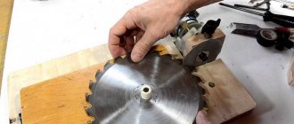
The simplest solution to this issue is shown in the photo. The simplest tilter, albeit with one engine mounting point and only three additional braces, which remove the main load from most of the central pillar. And it is already reinforced with an additional stiffening rib in the form of the same profile.
The question remains about the stability of the entire structure, since the supporting area is relatively small. In this case, you can consider the option of two mounting points for the motor on the stand. There is a double-sided mounting of the engine, which also distributes the load evenly across the racks, and a large supporting area, which prevents the structure from tipping over.
All dimensions shown in the drawing correspond to the dimensions of VAZ studs and landing planes, and the motor is secured by a locking pin from turning. The locking mechanism allows you to select one of sixteen positions, which is quite enough to service any engine. Good luck to everyone!
Difficulties in making a lift
The cost of a finished car lift is high, but a self-made version can damage a person working under it if the design is unreliable. The weight of the car should not exceed more than a ton; if the structure falls on a person, irreversible injuries can occur.
A homemade car lift is made according to prepared drawings, or versions of finished products are used. In the latter case, one has to rely on the author's high computational skills. Incorrect calculation of the base or one of the fastened units can lead to irreversible consequences, at best, damage to the lifted unit.
For a homemade kit, made with your own hands, you will need parts and components, without which assembly is impossible. You can find this type of component in large stores that sell construction equipment. If there are not enough funds for new parts, you need to go to scrap metal collection points and enterprises that write off old parts.
If you find an error, please select a piece of text and press Ctrl+Enter.
The lift-tipper is mainly intended for VAZ cars, but can be used for any other car weighing about 1000 kg. Such a lift-tipper allows you to lift the car and turn it in any direction by 30, 60, 90 degrees when performing welding work, processing the bottom, removing and installing the driveshaft, rear axle gearbox, etc.
A lift-tipper for lifting and turning a vehicle when performing welding work, processing the bottom, removing and installing a driveshaft, and a rear axle gearbox.
By lifting the front end, you can replace the clutch, steering rods, and unscrew the crankcase bolts. Lifting the rear of the car, replace the springs, rods, rear axle, and muffler. Using lift stands and additional equipment, the engine is removed and installed. When performing this work, the car is rolled manually. When replacing the cross member, the engine is only raised.
Read also: 1M95 combined lathe
Lift-tilter, lifting a car on two racks, lifting on one rack, removing and installing the engine, dimensions.
The lift-tilter consists of racks with built-in screw-nut transmissions and support units. The components and parts of the lift, as well as their variations, are shown in the figures below. The numbering of parts in the figures is continuous.
Racks for a car lift-tipper, drawings and dimensions.
There are two racks, they differ only in the traverses attached to them. Traverses differ in location (front and rear), as well as by type of car - for VAZ-2101, 2102, 2103, 2106 and for VAZ-2104, 2105, 2107.
The screw has a hexagon in the upper part, rotating which moves the nut with the front or rear traverse attached to it. The screw rests on bearing 8105 (dxDxH=25x42x11 mm) through a support. The support is connected to the screw with a pin. A square sheet is attached to the nut with two screws. A plate with a welded traverse (front) or (rear) is secured to the nut axis with a slotted nut and washer.
Screw-nut transmission of lift-tipper for VAZ cars.
The plate has seven holes designed to secure the plate with an M8 bolt to the square sheet and, therefore, to the post.
Welding of lift-tipper parts for VAZ cars.
Lift-tilter nut for VAZ cars.
Parts of the lift-tipper for VAZ cars, drawings and dimensions.
The stand is a channel with a groove. A support sheet is welded to the top of the rack. A diaphragm is welded into the rack. At the bottom of the rack, a base and two ribs are welded to the end. Three plates and four ribs are welded above the groove (34x52 mm). The bosses are pre-welded to the plates, after which an M10 thread is cut simultaneously in two plates and bosses. The racks are attached to the base channel using four M10-25 bolts.
Stand and support unit for lift-tipper for VAZ cars.
Base for a car lift-tipper.
The base of each rack consists of two channels. In the pictures, the channel is shown upside down for ease of drawing dimensions. Plates are welded to the channel at the ends. In the middle part, in size, four holes with a diameter of 10.5 are drilled. They are used to fasten the rack to the channel (M10-25 bolts with regular and spring washers).
The channel is inserted into the hole formed by the stand and base. Supports welded from plates are attached to the ends of the channel with bolts (M8-25) and nuts. The channel with supports is secured with bolts. When the bolts are loosened, the channel can be moved relative to another channel of the base.
Traverses for a car lift-tipper.
Crossbars for VAZ-2101, 2102, 2103, 2106 cars, front and rear, are channels No. 5 of various lengths. Diaphragms are welded into the traverses, and plates are welded to the ends. Traverses, as noted above, are welded to the plates. The crossbars are attached to the car after removing the bumpers with brackets using plates and fingers. The fingers are fixed in the traverses with M8-25 bolts, which are screwed into the fingers through the holes in the traverses.
Lift-tilter crossbars for VAZ-2101, 2103, 2106, for VAZ-2102 dimensions in brackets.
Traverses for VAZ-2104, 2105, 2107 cars have a slightly different design due to the difference in bumpers and their fastenings. If in the cases considered (VAZ-2101, 2103, 2106) the traverses were attached directly to the front and rear side members using plates, then it makes sense to use intermediate parts connecting the bumpers to the side members.
Engine tilter stand
Homemade stand tilter for disassembling and assembling engines.
I made an engine tilter; you can install the engine with everything attached to the device, turn it and lock it in the desired position. The device is made in such a way that nothing interferes with completely disassembling the engine down to the block.
Materials used:
- Channel - 60 mm.
- Channel - 50 mm.
- Pipes - 36 and 28 mm.
- Metal plates 8 mm - 2 pcs.
- Wheels from a cart.
- A piece of galvanized steel.
The homemade design is shown in the photo.
The axis of rotation of the engine is located at its geometric center.
The frame is made of 60 mm channel, racks with support hinges at the top are screwed to the frame. The hinges are made of pipes and open on hinges. After installing the assembled engine with legs on the stand, the hinges are closed and secured with nuts.
You can secure the engine in the desired position with a removable clamp; just loosen the clamp, turn the engine and tighten it.
On a pair of wheels diagonally, I made a stopper from a curved plate, which is bolted to the frame and clamps the wheel.
A tray made of galvanized roofing sheet is installed under the engine.
Dimensions: frame 600 x 800 mm, height of racks 350 mm.
Homemade author: Gleb. Minsk.
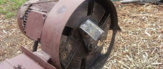
Sopranoo0 › Blog › DIY hub tippers
The bottom of my Okushka was a little rotten in the area of the front right arch and it was necessary to somehow treat this place. It was wildly inconvenient to clean rust from the pit, much less cook it.
I couldn’t really find any drawings on the Internet, so I had to think for myself. I cut out a template for the installation platform for the hub from thick cardboard based on the dimensions of the central hole and drilling of the Oka disk and brackets for them.
Next, from the remains of the 40th 4mm corners, I welded a base 70cm long.
Using the template, I cut out 2 mounting platforms from 4mm sheet steel. The central hole was cut by welding.
And 4 brackets from the same 4mm sheet.
The brackets must be identical to each other, otherwise the platforms will bend poorly. After cutting the brackets, I welded them together and clamped them in a vice so that they would not move relative to each other, I trimmed them with a grinder and drilled 10mm holes.
Then I cut 4 mounting eyes for the brackets from a 4mm strip and drilled 10mm holes.
I welded the eyes to the corners of the base of the tippers at a distance of 10cm from the edge.
I welded the brackets with the mounting platforms and fastened them to the base with 10mm bolts. I placed a washer between the eye and the bracket for easy rotation of the latter so that the metal does not rub against each other.
Then I used 20 corners to fix the longitudinal corners at the base at a distance equal to the width of the installation platform. All tippers are ready.
They withstood the eye with ease. At the first capsize there was not much creaking, but then everything was fine.
I placed a wooden plank to limit the angle of the car's collapse. I marked marks on the corners; later I will weld metal plates there in place of the board. I didn’t weld it right away because I didn’t know the optimal angle at which the car would stand on its own on the tippers without additional supports.
Drawings and photos of tilters for VAZ engines
The simplest solution to this issue is shown in the photo. The simplest tilter, albeit with one engine mounting point and only three additional braces, which remove the main load from most of the central pillar. And it is already reinforced with an additional stiffening rib in the form of the same profile.
The question remains about the stability of the entire structure, since the supporting area is relatively small. In this case, you can consider the option of two mounting points for the motor on the stand. There is a double-sided mounting of the engine, which also distributes the load evenly across the racks, and a large supporting area, which prevents the structure from tipping over.
All dimensions shown in the drawing correspond to the dimensions of VAZ studs and landing planes, and the motor is secured by a locking pin from turning. The locking mechanism allows you to select one of sixteen positions, which is quite enough to service any engine. Good luck to everyone!
Read more: How to convert kilowatts to amperes
After I made myself a crane www.drive2.ru/c/1481270/ there was still a little iron left, and I decided to also make a tilter for the engine, it’s still better to sort out the engine on a stand than on your knees, well, this is what came out of this idea
Engine tilter price
In principle, making a tilter for an engine with your own hands, the drawings and designs of which are posted on the page, is quite simple. Another thing is how useful it will be and how justified the use of garage space for its placement will be. Be that as it may, the equipment is very useful and functional, easy to manufacture and inexpensive in materials.
The price of a branded, factory-made tilting berth for passenger car engines will be at least 8 thousand rubles, and if you work hard and make a tilting crane with your own hands, you can save 20-25 thousand.
DIY engine removal crane, drawings
- Necessary materials
- Assembly instructions and drawings
- How to use
- How to make a garage goose crane with your own hands
- Simple powerful hydraulic crane
- Design features and operating principle
- Stationary
- Portable
- Main types of equipment
- By type of drive
- According to the design of the support
- What properties should a garage lift have?
- DIY crane assembly technology
- Schemes and drawings
- Material selection
- Step-by-step construction instructions
A DIY garage goose tap can be made from scrap materials available in the garage. This device is required when it is necessary to repair a car, for example, to remove the internal combustion engine from the car.
Homemade engine tilter
Many car enthusiasts repair their car engines on the garage floor or on a workbench. This is always inconvenient, associated with constant lifting of weights, tilting a bulky cylinder block or cylinder head. All these factors lead to excessive fatigue of the car mechanic and a decrease in the quality of engine assembly. To make their work easier, craftsmen have developed many homemade tilter designs for the engine.
Options for homemade tilter designs
There really aren't many options. In the West, complex and bulky home-made structures are known, like a crane beam, almost with hydraulic drives.
In domestic conditions, car enthusiasts assemble the simplest structures from what is at hand. Of the homemade tilters for the engine, two-support and cantilever versions are known. The last design is the easiest to manufacture. Its characteristics are sufficient to carry out major repairs of almost any passenger car engine weighing from 150 to 250 kg.
Before starting to manufacture the unit, it is necessary to study in detail the existing samples of stands for engine repair. The sample is selected to suit the immediate needs of an amateur car mechanic. The availability of materials and dimensions for ease of work in a small garage are assessed. The permissible load weight is calculated in accordance with the type of engine that is to be repaired.
Based on the results of a study of existing structures, a sketch drawing of the most optimal version of a cantilever-type tilter was developed. Overall dimensions in the diagram are given in millimeters.
In the sketch, the designations D 60 and D 52 correspond to diameters of 60 and 52 mm.
Materials for production
Due to the fact that the engine tilter will have to work under severe conditions of physical stress associated with the weight of the engine, high demands are placed on materials.
The following materials are used for manufacturing:
- steel square profile 70 x 70 with a wall thickness of 3 mm, length 3 m;
- steel pipe with outer diameter 60 mm, inner diameter 53 mm, length 245 mm;
- steel pipe with outer diameter 47 mm, length 480 mm;
- steel channel with internal side width 70 mm, wall thickness 3-4 mm, length 280 mm;
- flange for bolted connection to the engine - 1 pc.
Tools and hardware for stand assembly
To connect the nodes of a metal structure made of a steel channel and a square profile, you will definitely need a welding machine that allows you to work with an electrode with a cross-section of at least 3-4 mm. In addition, for cutting you will need a grinding machine with a metal cutting disc with a diameter of 115-125 mm. To ensure bolted connections of prefabricated parts, you will need a drill with the ability to work with a drill with a diameter of up to 14-20 mm. M12 bolts are also required to assemble the structure.
You will also need a set of files to cut off burrs and uneven edges, and remove flaws in metal cutting. It wouldn't hurt to purchase some sandpaper to remove rust from the surface before painting.
Assembly of the engine tilter
The first step is to cut out the channel and square profile in accordance with the sketch. Next, a vertical post is made from the profile and welded to the square from the channel. Then the structure is reinforced with metal slopes, which can be made from scrap parts.
After this, a base is welded from a cut square profile - a tilter stand for engine repair. At the site of the bolted connection to the base of the vertical post, preparatory work is carried out, steel bushings are inserted and welded to strengthen the structure.
Then you should begin the final assembly of the engine tilter. The stand is connected to the stand by welding and M12 bolts.
A horizontal pipe with an outer diameter of 60 mm and an inner diameter of 52 mm is welded to the vertical stand. A horizontal axis is inserted into this part. It can be made of a steel pipe with a diameter of 47 mm with a welded flange for bolting the cylinder block or cylinder head.
In the horizontal axis, you can drill through holes every 45° along the radius, to be able to fix the position in space with pins after rotating the attached motor to the required angle.
- home
- Articles
- Engine repair equipment
The engine can rightfully be called the “heart” of a modern car. It is this part that bears the greatest number of loads, and the performance of the entire vehicle directly depends on its performance. Owners fix some minor breakdowns on their own, but to fix more serious problems, you should contact specialized auto repair shops equipped with equipment for engine repair. A signal for the need to visit a car service center may be an increase in fuel consumption or difficulty starting the car. The technology for repairing any engine is built in several stages. First, the attached equipment is removed from it, then the assembled engine is washed.
After this, the motor is placed on an engine disassembly stand . This equipment for engine repair allows you to securely fix the part in a position convenient for work. Paradoxical as it may seem, often the cause of damage to car engines is dirt getting into them. Therefore, after disassembly, all its components are thoroughly cleaned.
A slightly more advanced model of a disassembly stand is an engine repair stand . It can be equipped with additional accessories, such as trays for collecting technical fluids.
After disassembling and washing the engine, it is necessary to inspect it, repair or replace damaged parts. For these purposes, specialized equipment for engine repair is also used.
Installations for honing cylinders of automobile engines are designed for honing cylinder mirrors. The operation is carried out in order to achieve proper seating of the piston rings. After all, only in this way can the required tightness of the fuel combustion chambers be achieved. The bushings of the upper and lower connecting rod heads, valve mechanism drives, and engine cylinders are honed. There are two types of honing stands on the market with different types of hone: a “bottle brush” and a surface hone, made in the form of an attachment with sharpening stones.
After all structural elements have been restored, the engines are assembled, tested and run-in at a stand for assembling and adjusting engine clutches .
Engine break-in stands are one of the most important types of equipment for engine repair. Many models allow for both cold and hot running, while others are designed for only one operation.
Cold running can significantly reduce the breakthrough of gases into the crankcase from the combustion chamber and the penetration of oil into it. The engine is connected to the stand and begins to run in, first at low speeds, then their frequency constantly increases.
Materials for production
Due to the fact that the engine tilter will have to work under severe conditions of physical stress associated with the weight of the engine, high demands are placed on materials.
The following materials are used for manufacturing:
- steel square profile 70 x 70 with a wall thickness of 3 mm, length 3 m;
- steel pipe with outer diameter 60 mm, inner diameter 53 mm, length 245 mm;
- steel pipe with outer diameter 47 mm, length 480 mm;
- steel channel with internal side width 70 mm, wall thickness 3-4 mm, length 280 mm;
- flange for bolted connection to the engine - 1 pc.
Homemade engine stand (tilter).
Making a homemade tilter stand for mounting and repairing the engine.
Some garage craftsmen who like to repair their own car with their own hands disassemble the engine on a workbench, and some even on a stool or box. But even for small-capacity engines, the cylinder block weighs several tens of kg, even without a cylinder head, crankshaft and flywheel. And when making repairs on a table, turning it over is quite difficult and dangerous, because you can inadvertently press your fingers, and you have to do this several times. And when disassembling it on a stool or some kind of box, there is always a risk of dropping the unit on the floor or feet. I propose to get rid of the inconveniences described above and make a simple stand for securing and fixing the engine in 16 different positions, which will make disassembling and assembling the engine a pleasure.
The stand, which will be described in this article, is designed for all engines of the VAZ family, both rear-wheel drive classics and front-wheel drive cars. It is also suitable for some foreign cars, namely Italian engines.
But if the mounting dimensions do not suit some motors of other machines, then you just need to make the motor mounts based on the dimensions of your particular unit, and the distance of 680 and 740 mm (see Figure 1) will also need to be changed based on the dimensions (length) your engine.
Most stands shown in various books, catalogs or the Internet have a cantilever motor mount (mounted to one side of the block) and only one stand. This design still causes some caution, and yet, based on the well-known proverb “one head is good, two are better,” it is still desirable to make a more reliable two-legged stand (with two stands, shown in Figure 1). Such a stand will be much more stable and reliable, and the price is just another profile pipe and another block mount.
Moreover, the double-sided fastening of the engine will make its installation much easier, and no hydraulic engine lift or several people will be required. Only two people of average build will be able to mount the engine on such a stand.
And at the moment when the special supports of the motor (see Figure 2) with their spikes 4 (axes) fall into the lower halves of the bearings 3 (they are shown in Figure 1), the engine is already suspended on the racks and is already quite stable. And if you also install the bearings in the desired operating position and tighten the covers with bolts 5, then the motor will already be securely fixed.
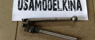
Flange 1 and rib 2 of the engine support (for Zhiguli) in a closer view.
Supports 5 (Fig. 2) of the stand are attached to the flanges on the engine block, for Zhiguli engines to the places of the brackets of the front engine supports, using four factory studs with a diameter of 8 mm. Before installing the engine on the stand, you need to unscrew one bolt 5 (see Figure 1) and turn the caps of each bearing 3 by 90 degrees - these simple steps will allow you to install the spikes of 4 supports into the bearings of the stand.
Close-up details of the stand. 3 — sliding bearing, 5 — bolt holding the bearing caps together (4 pcs), 6 — disk locking pin 3 (fixes the motor from turning)
After the motor is suspended on the stands in the bearings of the stand, you will need to turn the bearing caps to the working position and then tighten the bolts 5. And the 3 support discs are welded so that one of the discs is rotated relative to the other disc by 22.5 degrees. As a result, when using the left or right lock, you can set the motor in as many as 16 different positions, which will make it easy to disassemble or reassemble the engine, choosing the most convenient one for any operation.
When the desired comfortable position of the engine is selected, all that remains is to secure the engine from turning. To do this, you will need to insert the locking pin 6 (see Fig. 1) into the hole under the support bearing so that it fits into the hole in disk 4.
You can drill different holes in the racks, which are useful for temporarily placing the pins of the clamps or engine mounts so that they are always at hand. However, it is not necessary to drill a lot of holes in the racks; you can simply attach suitable small boxes to them for fastening.
If someone wants to make a more universal stand for different engines (of different lengths and even for longer 6-cylinder engines), then it can be done so that plates 10 - 12 mm thick are welded at the base of each rack (profile pipe), with four holes in the corners, and at the base of the stand you will need to weld not one profile pipe (the one 680 mm long), but two pipes that will be about a meter long. A series of matching holes (or slots) will need to be made in these two pipes. This will allow the struts to be moved and secured at different distances from each other, depending on the length of the block of any engine.
DIY garage lift
For use in the garage, it is possible to make a kit for lifting a car with your own hands. You will need the necessary components, tools and plumbing skills.
A homemade lift is made using the following parts:
- Steel corners measuring 8x8x1 cm, for making a stable structure.
- Worm type gearbox. A new product can be expensive; it is usually selected during disassembly or removed from a non-working mechanism. It is necessary to pay attention to the load capacity, the indicator starts from 350 kg, the transmission force indicator is 60 kg.
- A steel plate with a minimum thickness of 1 cm is removed from old equipment.
- Set of bolts, mounting hook, star-shaped keys.
- Several iron chains with a link diameter of 2 cm or more. Weak chains will not withstand the load, you should pay attention to the quality of the product, some materials can stretch during operation.
- Steel cable, 5 mm thick.
Assembly and installation of components occurs in the required sequence, following the proposed instructions. The steel corners are fastened to the walls in the opposite direction from the hood of the car. On top of the corners for the lift, a steel plate is installed with your own hands. The connection is made with prepared bolts. Next, you need to install the worm gear, securing it with a key on the drive shaft. A key of smaller diameter is installed on the output shaft of the gearbox.
DIY chain lift
Holes suitable for the diameter of the chain are made in the plate, after which the chain mechanism is installed. It is important to pay attention to safety; holes are made in the frame at a certain distance, and a locking mechanism is inserted with them.
Features of operation of such a lift
The use of a worm-type unit during operation is suitable for lifting a car engine or load-bearing parts. The procedure for using a self-made car lift is simple; you must follow these steps:
- Remove engine mounts, bolts, nuts.
- Afterwards, the steel cable loops are supplied and the structure is coupled.
- The drive shaft rotates by turning the chain; with a little effort you can slowly lift the part to the desired position.
Read also: Drilling holes in artificial stone
Worm type garage lift
After lifting, it is necessary to remove the car from the work area by placing a table under the engine. It is possible to make a stand or table with your own hands; the design must be durable and withstand heavy loads. Convenient to use is a table on wheels, which allows you to move the part in the required directions.
If the car is too big
Repairing large vehicles is not uncommon; wheel size and ground clearance may not allow you to raise the necessary parts to the required height. The process takes place with an assistant, who pulls the part onto a pre-prepared table. The gearbox rotates with the opposite side to the installed element.
Car lift for large cars
Such situations lead to thoughts about improving and modernizing a car lift for a garage with your own hands. It is possible to manufacture a movable structure that will make it possible to move the lifted part to the required distances. It is possible to make an aggregate installation with an electric motor on a reduction gear, in which case it can be a real crane for lifting large-sized mechanisms.
Purpose
Every driver wants a vehicle to be reliable in operation and serve for many years. But situations still happen when the main breakdown of the car is the engine. This is where you will need a stand for disassembling and assembling engines. There are different versions of it.
Such a stand is designed to significantly simplify the process of inspecting the unit, as well as troubleshooting, repair and depreciation. After removing the engine from the compartment, the unit is tightly and securely mounted on a special stand.
The time spent on work is reduced when a prefabricated service unit is available in a car repair shop or garage.
Brief instructions:
- Search for suitable jobs in the search bar at the top center of the page or in the side navigation bar on the left.
- Evaluate the quality of the work using the content and screenshots of the drawings that are in the archive. To view screenshots, download the archive from the payment page.
- If the work suits you, choose a payment method (Yandex-money, Frikassa or Interkassa) or use your personal account and personal account, which you can top up there.
- Expect the archive password to be sent to your email. To speed up receiving your password, you must fill out the payment form correctly - indicate your email address.
- For any questions, please contact the forum or call the phone number listed in the header of the site.
Varieties
Since 30 years ago there was not such a wide variety of cars that are now found on the roads, engine stands with rear axles and other accessories did not have versatility. They were not mass produced on the hardware market. There are currently many types of cars and trucks. And due to the growing demand for repair services for engines of various brands, car service centers have a need to use universal stands to meet the needs of the market.
Definitely such a device for engines is the most rational. It is suitable as a stand for disassembling and assembling Kamaz and YaMZ engines. R-776 is the most common in this area. Models R-500E and R-776 E are also popular. They are designed for servicing engines, gearboxes, and rear axles.
Also popular is the P-1250 model, which has a load capacity of up to 2 tons. It is universal and suitable as a stand for disassembling and assembling Kamaz engines. It matters how many degrees of freedom the stand has. There are models with 2 and 4 positions. Two degrees of freedom allow you to rotate the equipment up and down, right and left. More universal varieties are those with four degrees of freedom. They can be rotated as many degrees as you like and fixed at different angles for comfort.
Primary requirements
The main requirements for a stand for disassembling and assembling engines are versatility and ease of use. It is also important how many levels of freedom are provided in the design, what tonnage the selected equipment must withstand.
Currently, stores offer a wide range of options to choose from. You can assemble the structure yourself. This will save money and help you choose parameters in accordance with your wishes for personal ease of use.
A homemade installation must be durable and reliable. All metal elements are assembled by welding. In this case, it is better to seek help from a specialist. He will be able to qualitatively weld all the parts together. In this case, the safety of service personnel can be guaranteed while performing their activities.
Design elements
A typical stand for disassembling and assembling engines consists of a list of certain materials that are taken as a basis for assembly. The list includes several design components. This is a plate to secure the internal combustion engine, a stand base, a special tray for escaping waste material, and a rotating mechanism.
Also, for greater convenience and versatility, the equipment should be able to move around the room. To do this, install durable wheels at the bottom of the structure.
Description of design
A car tipper for a car, a drawing, video and photo of which are presented below, it works using a jack:
You can take any lift that is in the garage. The maximum possible angle for safely raising the side of the vehicle is 45 degrees.
The heel for the jack should have as many stiffening ribs as possible, which will give it additional strength. This is an important point, since during operation of the tipper the part moves along the rail, experiencing loads in the region of 2.5 tons. A heel is welded from sheet metal (5 - 7 mm).
We make a tipper for a car with our own hands: a drawing of the design described below
The same applies to the platform that will rest against the bottom of the car - we make more stiffeners, we use metal with a thickness of 5 - 7 mm. Additionally, you will need a metal corner and a square profile. The bottom platform, support corner and support beam are made from the same profile.
The lower platform is a stationary part made of one metal profile that will lie on the ground. The support angle consists of two elements connected to each other by short sections of metal profile and moves up and down along the guide rail. The latter has a number of holes for fixing the tipper at the desired angle.
Bottom platform and support angle assembly
The row of holes that you see on the sides of the support angle serves to fix the platform on which the bottom of the machine will rest. When raising/lowering the car, it moves along the part in one direction or another. At the highest point, when the rise is completed, the platform is fixed with a bolt. The platform and the support corner are fastened together with a bolt.
Assembly
If the installation will need to serve various types of engines or simply be for all occasions, then it should be made universal. It should be taken into account that VAZ car engines differ significantly from BMW mechanisms in fastening methods. It may be necessary to create a stand for disassembling and assembling the KamAZ-740 engine or other large-sized engines.
A pair of channels with 10 mm holes is welded to the rotation plate. The pitch is 50 mm. Places for channels are marked in the area of the motor mounts. The center of gravity is precisely directed along the axis of rotation of the plate. This will make it possible to simply rotate the stand around its axis.
Using a manual hoist makes it possible to install the structure on wheels (they must be strong enough). This will make it easier to move the faulty part around the room. If necessary, it can be easily moved to the far corner. You should also attach a tray at the bottom, thanks to which the dirty waste from the engine will not spill on the floor. The existing pan below will make it possible to flush the engine.
Tipper installation
We stretch the support platform for the car tipper with our own hands under the bottom of the car. In this case, we place the place for fixing the heel for the jack on the side that must be raised. We insert a support corner on top and fasten it to the platform with a bolt. Next, we assemble and insert the support beam into the fixture. First, remove the caps from the wheels to which it will be adjacent.
The heel for the jack is inserted between the platform and the support angle, then a rail with a number of through holes is vertically inserted through all three parts. It serves as a guide and retainer for the top of the inverter. The lower end of the rail is screwed to the platform with a bolt. We lubricate the sections of the support corner profiles along which the platform will move with grease and only then install it, moving it under the bottom of the car.
Next, attach a jack to the tipper and begin lifting. After the desired height is reached, a cotter pin is inserted into the vertical rail through the hole located directly under the support angle. It will prevent the car from falling if something happens to the jack. The following video describes in detail how to install a homemade car tipper with your own hands.
Cars tend to break down and require periodic maintenance, like any equipment. Access to the lower part in garage conditions is often impossible due to the lack of a lifting device. Having all the necessary tools, a lift equipped and ready for work, it is possible to replace the consumables of the chassis, transmission, and engine. Despite the fact that the device is in demand when repairing cars with your own hands, purchasing it for use for your own needs is very expensive. Maintenance can be performed no more than twice a year, so it is better to make units and components yourself.
Read also: Device for finding a broken wire
Assembly of the engine tilter
The first step is to cut out the channel and square profile in accordance with the sketch. Next, a vertical post is made from the profile and welded to the square from the channel. Then the structure is reinforced with metal slopes, which can be made from scrap parts.
After this, a base is welded from a cut square profile - a tilter stand for engine repair. At the site of the bolted connection to the base of the vertical post, preparatory work is carried out, steel bushings are inserted and welded to strengthen the structure.
Working with the stand
Before starting operation, be sure to carry out a visual inspection of the system. If any defects are discovered that could damage the equipment during maintenance, they must be corrected. If upon inspection there are no such defects, you can begin work.
For a good and long service life of the structure, it is necessary to monitor its condition. It is necessary to check the reliability of the fixing fasteners each time you use it, regularly lubricate all moving parts and store the unit in a dry place. The possibility of direct contact with precipitation and moisture should be excluded.
You should not load the stand above the actual calculated weight, so as not to drop the engine due to breakdown. During operation, the structure must be placed on a stable surface. It is also worth using a locking pin for the rotating mechanism. You should work carefully and carefully.