How to make transformers T1 and T2?
The first transformer T1 with a power of 3 kW is manufactured using a magnetic core with a cross-sectional area (CSA) of 187 sq. mm. And three wires PEV-2:
- For the first wrapping, the PPS is only 0.003 square meters. mm. Number of turns – 8669;
- For the second and third windings, the PPS is only 0.027 sq. mm. The number of turns is 522 on each.
If you don’t want to wind the wire, then you can purchase two TPK-2-2×12V transformers and connect them in series, as in the figure below.
To make an autotransformer with a second power of 6 kW, you will need a toroidal magnetic core and PEV-2 wire, from which a wrap of 455 turns will be made. And here we need bends (7 pieces):
- Wrapping 1-3 bends from wire with PPS 7 sq. mm;
- Wrapping 4-7 bends from wire with PPS 254 sq. mm.
Taps are made on turns (counting from bottom to top): 203, 232, 266, 305, 348, 398. From the network, voltage should be supplied to turn No. 266.
Connection features
The procedure for connecting inverter-type stabilizers is not very complicated and does not take much time. However, it is better to entrust it to a master.
Before connecting the device, you must turn off the power to the entire home network. The rectifier can be connected either in front of specific devices or immediately after the meter.
Many inverter models are connected to the network via terminals. First, the input wiring is connected, which will supply current. To do this, you need to establish in the power panel which cable is “zero” and which is “phase”. Don't forget about grounding either.
The wire with the “phase” is connected to the terminal - designated L or L1. The wire with “zero” is connected to the zero terminal. The cross-section of the input wiring should not be less than 2.5 mm.
How to make transformers T1 and T2?
The first transformer T1 with a power of 3 kW is manufactured using a magnetic core with a cross-sectional area (CSA) of 187 sq. mm. And three wires PEV-2:
- For the first wrapping, the PPS is only 0.003 square meters. mm. Number of turns – 8669;
- For the second and third windings, the PPS is only 0.027 sq. mm. The number of turns is 522 on each.
If you don’t want to wind the wire, then you can purchase two TPK-2-2×12V transformers and connect them in series, as in the figure below.
To make an autotransformer with a second power of 6 kW, you will need a toroidal magnetic core and PEV-2 wire, from which a wrap of 455 turns will be made. And here we need bends (7 pieces):
- Wrapping 1-3 bends from wire with PPS 7 sq. mm;
- Wrapping 4-7 bends from wire with PPS 254 sq. mm.
Taps are made on turns (counting from bottom to top): 203, 232, 266, 305, 348, 398. From the network, voltage should be supplied to turn No. 266.
Types of stabilizers
All industrial designs of such equipment can be divided into two large groups:
- electromechanical;
- pulsed.
Electromechanical
The operation of electromechanical devices is based on a servo drive, which is capable of changing the number of winding turns (and therefore the output voltage) by moving a conductive slider along a rheostat. Such devices are cheaper than all other models and have very good stabilization performance. However, they are more likely to break due to the presence of many mechanical parts.
But their main disadvantage is the response speed. Due to the fact that the drive does not move the current collector instantly, the stabilization delay can be up to 0.1 seconds, which is catastrophically long for devices that are sensitive to differences. In other words, such a stabilizer may simply not have time to protect modern electronics. In addition, due to the presence of mechanical parts, reproducing such a device at home is a non-trivial task.
Pulse
Stabilizers are called pulse stabilizers, the operation of which is based on the principle of accumulating current and distributing it to the consumer in fragments - pulses. These time intervals allow the system to accumulate the required current in the capacitors, and then provide stabilized power. Such devices also include devices whose operation is based on triacs and thyristors.
Such devices are more expensive than their electromechanical counterparts, but they are also much more reliable - there are no rubbing or moving parts, which means that, in fact, there is nothing to break. True, their stabilization indicators are worse - they are only capable of a proportional increase or decrease in input indicators. But the response speed is up to 20 milliseconds, and this is enough to protect even the most sensitive household electrical appliances. In addition, such a device can be assembled with your own hands, having the necessary skill and element base.
In addition to separation according to the principle of stabilization, there is a separation into single- and three-phase devices. But due to the fact that single-phase power is usually used at home, we do not take three-phase devices into account.
Operating conditions of the device
During the current conversion process, it is necessary to protect the device from moisture, dust, overheating and mechanical damage. The device cannot be put into operation if condensation has formed in the housing due to a change in ambient temperature ; to protect the stabilizer from a short circuit, it is necessary to wait until the moisture has completely evaporated from the internal elements of the equipment.
A self-made current rectifier made in a private workshop can only be used in dry rooms where there are no rodents, insects, explosive or flammable materials. To stabilize the frequency of current fluctuations, the device must be installed in an open space, at a distance of at least 50 mm from the wall, and a neutral or phase cable must be used.
Which is better: relay or triac
If we compare a triac stabilizer and a relay or thyristor stabilizer, then the first one is undoubtedly a more reliable, durable and safe device. This is explained by the absence of switches with moving contacts, the presence of a control board, a powerful autotransformer and power triac switches. The only drawback of triac stabilizers, compared to other devices, is their high cost, which over time justifies itself with a long service life and high reliability.
Thus, the device described in this article allows us to effectively deal with such a problem for many owners of apartments, country houses and country houses as voltage surges in the electrical network. The use of a stabilizer allows you to reduce to zero the risk of breakdown of electrical appliances and subsequent expensive repairs from short-term power surges in the network. The big difference in the price of such devices, compared to analogues, is several times less than the cost of repairing or purchasing new devices and equipment damaged by surges in unstable network electric current.
Device
A design feature of triac-type stabilizers is the presence of the following mandatory components:
- an automatic transformer equipped with a pair of windings connected directly;
- controllers;
- power type keys.
The controllers regulate the input voltage by comparing the readings with the nominal values. This principle of operation allows the triac stabilizer to respond to any changes as quickly as possible.
Voltage stabilizer thyristor (triac) SUNTEK TT 10000 va low input voltage
It should be noted that the level of accuracy when leveling voltage indicators directly depends on the number of steps in the adjustment. With a minimum control step and a significant number of steps, a more accurate stabilization process is carried out.
Assembly features of the device for voltage equalization
The current stabilizing device microcircuit is installed on a heat sink, for which an aluminum plate is suitable. Its area should not be less than 15 square meters. cm.
A heat sink with a cooling surface is also necessary for triacs. For all 7 elements, one heat sink with an area of at least 16 square meters is sufficient. dm.
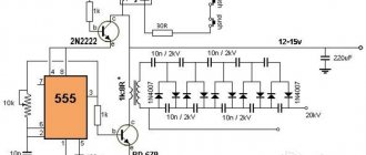
In order for the AC voltage converter we manufacture to work, you will need a microcontroller. The KR1554LP5 microcircuit copes with its role perfectly.
You already know that you can find 9 flashing diodes in the circuit. All of them are located on it so that they fit into the holes that are on the front panel of the device. And if the stabilizer body does not allow their location, as in the diagram, then you can modify it so that the LEDs come out on the side that is convenient for you.
Now you know how to make a 220 volt voltage stabilizer. And if you have already had to do something similar before, then this work will not be difficult for you. As a result, you can save several thousand rubles on the purchase of an industrial stabilizer.
Safety precautions when assembling a voltage stabilizer with your own hands
We should have placed this item earlier, but we hope that you have not started work yet. Use extreme caution when assembling the stabilizer. Do not touch the exposed contacts with your hands if the stabilizer is energized.
Monitor your actions carefully . Do not work while drunk or in the presence of children. It is worth noting that it is inconvenient to connect the product to the network each time and then pull out the plug. Before assembling the stabilizer, we recommend organizing your workplace as follows. Install a special socket on the table and make it so that voltage can be supplied to it by pressing the pedal.
Firstly, your hands will be free, and secondly, in emergency situations, the pedal can be released much faster than pulling the plug from the socket. You can use a purchased one or a homemade one as a pedal by securing the button between two boards.
To avoid the consequences of an accidental short circuit, supply the mains voltage to the stabilizer not directly, but through a powerful load, for example, through an oil heater or through an iron. The good thing about the iron is that it is compact and always at hand, but you can get burned on it. If possible, it is better to choose something else from your equipment.
Comments:
Cherevaty
Informative article, thank you. The diagrams are detailed and easy to read. There will be something to do on vacation. I want to throw such a stabilizer under a homemade wind station that powers a light bulb in a gazebo. Do you think the scheme will work?
Gaivoronsky
I assembled everything according to the diagram - everything works, thanks to the author. I will continue to experiment with a soldering iron and printed circuit boards.
Slavon
Uff... Does anyone know where all the parts can be bought? So that in one place you don’t have to overpay for the delivery of one relay, otherwise the stabilizer will turn out to be more expensive than a store-bought one
We advise you to study 10 simple charging schemes for lithium-ion batteries and how to charge them correctly
Alex
Slavon, yes, all these parts are sold on any piece of hardware. Don't bother. In any case, they are cheaper on the market, and you can buy used ones (but only if they are Soviet) - so in general the price turns out to be a pittance
Oleg Kyiv
The language of presentation certainly deserves special attention.
Vyacheslav
How were you able to repeat the design if there is no data on the magnetic circuit for the T2 transformer?
Sergey
How to convert the divider to a voltage of 100-250 volts?
Disadvantages of ET models offered on the market
Cheap models do not have special overload protection.
Despite the economical and well-developed design, electric power supplies have a number of disadvantages, which are usually classified as:
- lack of special overload protection in the simplest Chinese models;
- the resulting need for mandatory modification of the scheme;
- Many market samples do not have an input filter device, which forces them to add a smoothing electrolytic capacitor (it is placed after the “powerful” choke).
The listed disadvantages usually include the “hard” operating mode of high-voltage transistors connected according to a key circuit.
In the event of an accidental output short circuit (SC), these elements simply “burn out,” which leads to the need for an urgent update of the entire electronic module. Often, the rectifier based on semiconductor diodes also breaks down and also needs to be replaced.
Manufacturing stages
To assemble a 220V voltage stabilizer for your home with your own hands, you first need to prepare a printed circuit board measuring 115x90 mm. It is made of foil fiberglass. The layout of the parts can be printed on a laser printer and transferred to the board using an iron.
Let's watch the video, a homemade simple device:
electrical circuit diagram
Next we move on to assembling the transformers. For one such element you will need:
- magnetic core with a cross-sectional area of 1.87 cm²;
- three PEV-2 cables.
The first wire is used to create one winding, and its diameter is 0.064 mm. The number of turns should be 8669.
The two remaining wires will be needed to make other windings. They differ from the first one in diameter being 0.185 mm. The number of turns for these windings will be 522.
If you want to simplify your task, you can use two ready-made TPK-2-2 12V transformers. They are connected in series.
In the case of making these parts yourself, after one of them is ready, they move on to creating the second. It will require a toroidal magnetic circuit. For the winding, choose the same PEV-2 as in the first case, only the number of turns will be 455.
Also in the second transformer you will have to make 7 taps. Moreover, for the first three, a wire with a diameter of 3 mm is used, and for the rest, buses with a cross-section of 18 mm² are used. This will help prevent the transformer from heating up during operation.
connection of two transformers
It is better to purchase all other components for a device you create yourself in a store. Once everything you need has been purchased, you can begin assembly. It is best to start by installing a microcircuit that acts as a controller on a heat sink, which is made of aluminum platinum with an area of more than 15 cm². Triacs are also mounted on it. Moreover, the heat sink on which they are supposed to be installed must have a cooling surface.
Next you need to install LEDs on the board. Moreover, it is better to choose blinking ones. If it is not possible to arrange them according to the diagram, then you can place them on the side where the printed conductors are located.
If assembling a 220V triac voltage stabilizer with your own hands seems complicated to you, then you can opt for a simpler linear model. It will have similar properties.
The effectiveness of a handmade product
What pushes a person to make this or that device? Most often - its high cost. And in this sense, a voltage stabilizer assembled with your own hands is, of course, superior to a factory model.
In addition, all the parts for such a device were previously purchased in the store, so if they fail, you can always find a similar one.
If we compare the reliability of a stabilizer assembled with our own hands and manufactured at an enterprise, then the advantage is on the side of factory models. At home, it is almost impossible to develop a model with high performance, since there is no special measuring equipment.
Conclusion
There are different types of voltage stabilizers, and some of them are quite possible to make with your own hands. But to do this, you will have to understand the nuances of the operation of the equipment, purchase the necessary components and carry out their proper installation. If you are not confident in your abilities, then the best option is to purchase a factory-made device. Such a stabilizer costs more, but the quality is significantly superior to models assembled independently.
Main assembly steps
Correct assembly of the voltage stabilizer will ensure its long-lasting and uninterrupted operation. Therefore, all elements must be soldered according to the diagram, otherwise a short circuit may occur.
Stabilizer assembly sequence:
- A fuse must be soldered in series to one of the wires entering the device input. This will help avoid excessive loads as well as short circuits.
- Next, the circuit components are installed on the breadboard, with the exception of the power ones, which will be installed separately.
- Then you need to make connections and solder with wire for installation.
- After sealing the logical part of the circuit and the power supply, it is necessary to check the operating logic without connecting the controls for optosimistors and triacs. Using LATR, applying voltages of different levels to the input, make sure that the correct LEDs are activated.
- After this, you can complete the assembly of the device and perform a final check, after once again making sure that the installation was performed correctly.
Connection errors
1
You may have everything connected perfectly and the diagram followed, but the stabilizer will constantly heat up and turn off, or errors will appear on its display.
Read in detail about where you can and where you should never place this device in the article “Where to install a voltage stabilizer in the house.”
2
Of course, this point can hardly be called a mistake. Moreover, 90% of consumers do just that.
However, this switch can really save your device from failure.
First you turn off the machines on the stabilizer panel.
Then move the switch itself to the TRANSIT or BYPASS position.
And only then turn on the machines again.
Many people forget about this and switch under load. Which ultimately leads to breakdowns.
With a 3-position automatic machine this is impossible. You automatically switch the voltage, without any manipulation on the stabilizer. And all this with one key!
There is no need to remember any sequence. So this procedure can be safely trusted to any family member.
3
You can choose a smaller cross-section only when powering individual electrical receivers.
If your whole house is sitting on a stabilizer, then please follow the input parameters according to the entire general house load.
4
For some reason, many people forget that often the entire load of your home passes through the stabilizer. Exactly the same as on the automatic input.
At the same time, in the electrical panel all the wires are crimped, even on light switches with minimal currents, but on the terminal blocks of the stabilizer or its circuit breakers, you can always find a bare wire simply pressed in with a screw.
Therefore, do not skimp and purchase the appropriate tips along with the device in advance.
5
Sometimes after connecting the stabilizer, the input machine starts to knock out. In this case, without a stabilizer, everything is fine and nothing is turned off.
Many people immediately blame it on an incorrect connection diagram or a defect in the device. They take it for warranty repairs, etc.
But the reason may be completely different. If your voltage is too low, 150-160V, then when you increase it to the standard 220-230V, the current in the network will increase significantly.
Hence all the problems
Please pay attention to this before you take it back to the store.
Sources - https://cable.ru, Kabel.RF
There is no need to work with your hands on the body of your stabilizer!
Since we are going to install our voltage stabilizer in the panel, then its body must satisfy this.
Fortunately, the industry foresaw our needs by releasing ready-made housings for REO, and we don’t have to do anything with our hands. The one we need is produced by Gainta Industries. Its cost is about 300 rubles, which for such a product as a voltage stabilizer is perceived to be within the “price error limits”, that is, it is not very expensive. It is convenient to place two of your boards in this case, and then just snap it into place and the product is ready. It is not possible to open the case back with bare hands, so if the voltage stabilizer needs to be disassembled, you will need a screwdriver.
By the way, the plastic of the case has the appropriate certificates for resistance to temperature and stress, which is very suitable for our final product.
Determining the type of protection
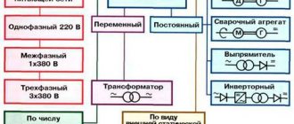
Today, stabilizers are divided into 2 main types:
- stationary devices for voltage stabilization, their installation is done for the whole house;
- portable models, they can stabilize the operation of just a few electrical devices.
Also, stabilizers for stationary use are divided into single-phase and three-phase, it all depends on the conditions in which they are planned to be used. In your house or apartment, it would be more appropriate to install and connect a stabilizer near the electricity distribution board; with this step you can prevent failures and overloads of the entire network.
We advise you to study the phenomenon of electromagnetic induction
220V voltage stabilizer circuit for home, operating principle, installation
How to make a 220V voltage stabilizer for your home yourself - necessary components and tools, diagram, assembly algorithm, video.
- Principle of operation
- Diagram, components and tools
- Installation
A change in the values of current and voltage in electrical networks towards a decrease or increase should be no more than 10% of the nominal 220 V. But in reality, surges are characterized by large changes, and therefore electrical appliances connected directly to the network may fail.
Using special equipment will help you avoid trouble. But since it is not cheap, many people prefer to assemble a voltage stabilizer for their home with their own hands. How justified is such a step and what will be required to implement it? Let's talk about this!
Choosing a voltage stabilizer for a computer
A computer consists of a system unit and a monitor. Therefore, the power must be summed up. Also, if the stabilizer also includes additional devices (scanner, printer, etc.), then all the power must be summed up and the resulting result compared with the range of ratings of the voltage stabilizers in question. As a rule, for a home computer you can choose a stabilizer with a power of no more than 1000 W.
For a computer, I also recommend using Smart UPS (interactive UPS) instead of a stabilizer. They contain a stabilization function (relay type) and have a battery. Thus, the voltage will be relatively stable and the reserve will be ensured.
Some models of inverter stabilizers
As a compact household stabilizer, you can consider the Shtil R 3500 inverter voltage stabilizer. This is a single-phase stabilizer that is perfect for working with low-power consumers. The device operates at voltages from 90 to 310V and provides a smooth sine wave at the output. Its error is 220V ± 2%. It can withstand an overload of 150% for about 5 seconds.
If you need to install a more serious model, then you can pay attention to the 10 kW inverter voltage stabilizer Powercom AR-10K. This device is capable of supporting a powerful load. The output parameters of this stabilizer meet the most stringent criteria. It has all types of protection and information display. It is quite expensive, and if there are no strict requirements for output parameters, then you can get by with cheaper models.
Principle of operation
Such a stabilizing device works as follows:
- The voltage supplied to the device from the external network is measured by the control board (controller) using a special sensor;
- Based on the measurements obtained, the controller makes a decision to adjust the voltage;
- The controller sends the corresponding signal to the input triacs;
- Using the signal sent to the triacs by the controller, a voltage equalized to a certain value is supplied;
- Using an autotransformer located in the housing, the voltage supplied from the external network is equalized to the value necessary for the normal operation of electrical appliances.
This multi-step process takes a fraction of seconds. At the same time, unlike relay models, the presence of triacs makes it possible to turn on and off the transformer windings silently and very quickly.
Types of modern devices
The development of semiconductor technology has made it possible to control power using radioelements with an efficiency of eighty percent. This made it possible to comfortably use them in a network with a voltage of 220 volts, without requiring large cooling systems. And the advent of integrated circuits made it possible to achieve miniature sizes of the entire regulator as a whole.
Currently, production produces the following types of devices:
- Phase. Used to control the brightness of incandescent or halogen lamps. Another name for them is dimmers.
- Thyristor. The operation is based on the use of a delay in switching on a thyristor switch during a half-cycle of alternating current.
- Triac. Power is regulated by changing the number of voltage half-cycles that act on the load.
- Travel regulator. Allows you to smoothly change the electrical power supplied to the electric motor.
In this case, the adjustment occurs regardless of the shape of the input signal. Based on their location, control devices are divided into portable and stationary. They can be carried out either in an independent housing or integrated into the equipment. The main parameters characterizing electrical energy regulators include:
- smooth adjustment;
- operating and peak power input;
- range of input operating signal;
- Efficiency
Thus, a modern electrical power regulator is an electronic circuit, the use of which allows you to control the amount of energy passed through it.
Thyristor control device
The operating principle of such a device is not particularly complicated. Basically, a thyristor converter is used to control low-power devices. A typical circuit of a thyristor power regulator consists directly of the thyristor itself, bipolar transistors and resistors that set their operating point, and a capacitor.
Transistors, operating in switching mode, generate a pulse signal. As soon as the voltage value on the capacitor is compared with the operating voltage, the transistors open. The signal is supplied to the control output of the thyristor, opening it too. The capacitor is discharged and the key is locked. This repeats in a cycle. The longer the delay, the less power goes to the load.
The advantage of this type of regulator is that it does not require adjustment, but the disadvantage is that it generates excessive heat. To combat overheating of the thyristor, an active or passive cooling system is used.
This type of regulator is used to convert power supplied to both household appliances (soldering iron, electric heater, spiral lamp) and industrial ones (soft start of powerful power plants). Switching circuits can be single-phase or three-phase. The most used: ku202n, VT151, 10RIA40M.
Triac power converter
A triac is a semiconductor device intended for use in an alternating current circuit. A distinctive feature of the device is that its terminals are not divided into anode and cathode. Unlike a thyristor, which passes current in only one direction, a triac conducts current in both directions . That is why it is used in AC networks.
An important difference between triac circuits and thyristor circuits is that there is no need for a rectifier device. The principle of operation is based on phase control, that is, on changing the opening moment of the triac relative to the transition of the alternating voltage through zero. This device allows you to control heaters, incandescent lamps, and electric motor speeds. The signal at the output of the triac has a sawtooth shape with a controlled pulse duration.
Independent production of this type of device is easier than thyristor one. Medium power triacs of the following types have gained wide popularity: BT137–600E, MAC97A6, MCR 22−6. The power regulator circuit based on a triac using such elements is characterized by ease of manufacture and no need for configuration.
Phase transformation method
The dimmer itself has a wide range of applications. One option for using it is to adjust the lighting intensity. The electrical circuit of the device is most often implemented on specialized microcontrollers that use a built-in electronic voltage reduction circuit in their operation. Because of this, dimmers are able to smoothly change power, but are sensitive to interference.
Read also: Where to fill propane gas cylinders
Phase power regulators are not stabilized using zener diodes, but use thyristors operating in pairs as a stabilizer. The basis of their operation lies in changing the opening angle of the key thyristor, as a result of which the load receives signals with the initial part of the half-cycle cut off, reducing the effective voltage value. The disadvantages of dimmers include high ripple factor and low power factor of the output signal.
When dimmers operate in a wide range of frequencies, electromagnetic interference is generated. Such radiation leads to a decrease in efficiency due to the appearance of parasitic current in the conductors. To combat such currents, inductive-capacitive filters are added to the design.
Advantages and disadvantages
The advantages of such a device include:
- High performance - the device, thanks to the presence of high-speed switching simulators, is able to respond very quickly to voltage surges in the network, smoothing them out to the required value;
- Wide range of input voltage - stabilizers of this type are capable of operating at input voltage values from 95 to 275 V (for a single-phase model), from 260 to 470-471 V (for three-phase stabilizers);
- High accuracy of stabilization - the output voltage produced by such devices has a maximum fluctuation within 1.5% (3.3-5.7 V), which does not have a negative impact on the operation of the devices connected to it.
- Monitoring the values of the input and output potential difference with an error of no more than 0.5%;
- High efficiency - thanks to the use of a triac, the value of this indicator for most models reaches 95-97%;
- Silence – the absence of relay switches and moving contacts in the design of the stabilizer allows it to operate almost silently;
- Small dimensions - stabilizers assembled on triacs, compared to relay ones, are small in size and can be compactly placed on the floor or wall of even the smallest room;
- Long service life - most modern high-quality models can normally perform their functions for 10 years or more;
- High power - various models are capable of ensuring normal operation of connected devices and equipment with a total power of 3 to 10 kW.
The disadvantages of such stabilizers include:
- High cost - high-quality models of stabilizers have a fairly high cost, which is not always affordable for many owners of apartments and houses.
- An abrupt change in the potential difference at the output of the device - this drawback is typical for inexpensive Chinese-made models. It practically does not appear in more expensive analogues.
On a note. Despite the high cost of such devices, their purchase in case of problems with the network voltage will be very profitable and will pay for itself quite quickly - if the stabilizer is missing, serious breakdowns of sensitive household appliances, pumping and heating equipment can occur. In some cases, such surges not only damage devices connected to the network, but also render them inoperable, which requires their replacement, leading to unplanned and significant financial expenses and other inconveniences.
Measuring the voltage of the stabilizer when switching it “by hand”
Let's return to our transformers and try to figure out how they can be used to change the voltage up and down. To do this, we connect the 220 V windings in parallel, and the 25 V windings in series. We get a circuit of a certain “bi” transformer with a wide possibility of switching windings. Let's take the current-voltage characteristic at a load of 120 W (the expected power of the boiler), while changing the circuit by hand. The pictures show what the stabilizer will produce when the voltage changes from 160 to 285 Volts.
As the experiment showed, the future stabilizer is capable of handling voltages from 160 to 280 Volts. At the same time, being within its range, the system produces a voltage at the output with an error of no more than 8%, which is sufficiently consistent with the standards. It's time to free your hands and make regulation automatic.
Additional functions of voltage stabilizers
In addition to the main function of voltage stabilizers - stabilization, there is also the following minimum set of functions and parameters:
Maybe this will be interesting too?
- Output voltage analysis. The stabilizer must be equipped with an information (digital or pointer) display that shows the output voltage. If the stabilizer has an input voltage analysis function, this will be additional useful information.
- At higher ratings (usually from 3000 VA), the “Bypass” function is installed - a function in an electronic device (signal processing, voltage stabilization, etc.) that allows you to switch the input signal directly to the output, bypassing all functional blocks. That is, the ability to turn on the network bypassing the voltage stabilizer. If the voltage has returned to normal or you do not need a stabilizer now, press the lever up and the voltage goes bypassing the stabilization blocks.
- Types of fastening of voltage stabilizers There are two types of fastening of voltage stabilizers - floor and wall versions. Floor-standing design means that the stabilizer is located on the floor or shelf. This arrangement is not always convenient, because especially large denominations cannot be placed on a shelf due to their weight, and they occupy quite large areas on the floor. When mounted, the stabilizers are made flatter for the convenience of customers. In principle, they can also be used in a floor-standing version, only often the information part of the display is in this case “upside down” towards the user.
- Many models on the voltage stabilizer market use a delay button. This is done so that if the voltage in the network disappears or temporarily goes beyond the operating range, the equipment will come to a rest position during this delay time before the next turn on. In many stabilizers, the delay button is offered in several ranges -6, 90, 120 sec. In more modern models, the delay has already become automatic and when it is turned on, it shows the consumer on the display the time the stabilizer is turned on in the form of a countdown.
Stabilizer characteristics
This stabilization device will not have increased sensitivity to changes in voltage supplied through the common line. Voltage smoothing will be carried out if the input voltage is in the range from 130 to 270 volts.
Devices connected to the network will be powered by a voltage ranging from 205 to 230 volts. From such a device it will be possible to power electrical devices with a total power of up to 6 kW. The stabilizer will switch the consumer load in 10 ms.
Assembly features of the device for voltage equalization
The current stabilizing device microcircuit is installed on a heat sink, for which an aluminum plate is suitable. Its area should not be less than 15 square meters. cm.
A heat sink with a cooling surface is also necessary for triacs. For all 7 elements, one heat sink with an area of at least 16 square meters is sufficient. dm.
In order for the AC voltage converter we manufacture to work, you will need a microcontroller. The KR1554LP5 microcircuit copes with its role perfectly.
You already know that you can find 9 flashing diodes in the circuit. All of them are located on it so that they fit into the holes that are on the front panel of the device. And if the stabilizer body does not allow their location, as in the diagram, then you can modify it so that the LEDs come out on the side that is convenient for you.
Now you know how to make a 220 volt voltage stabilizer. And if you have already had to do something similar before, then this work will not be difficult for you. As a result, you can save several thousand rubles on the purchase of an industrial stabilizer.
↑ Schematic diagram
It consists of an autotransformer switched both at the input and output using a relay. The circuit uses direct measurement of alternating voltage by a microcontroller. Output voltage through divider R13, R14, R15, R16
is supplied to the input of the microcontroller through capacitor
C10
.
The relay and microcircuit are powered through diode D3
and microcircuit
U1
.
Button SB1
together with resistor
R1
are used to calibrate the stabilizer.
Transistors Q1-Q4
are amplifiers for relays.
Relays P1 and P2 are the main ones, and relays P1a and P2a, together with diodes D1 and D5, close the circuit when switching the main relays. To reduce the relay turn-off time in relay amplifiers, BF422
and the relay windings are shunted with
1N4007
and 150 Volt Zener diodes connected back to back. To reduce impulse noise coming from the network, capacitors C1 and C11 are installed at the input and output of the stabilizer. A three-color LED indicates voltage levels at the stabilizer input: red – low, green – normal, blue – high.
Operation of the Suntek electromechanical stabilizer
To change the input voltage, an autotransformer is used, which can change the voltage within the required limits. In this case, the voltage at the output of the stabilizer does not go beyond the operating range.
In rural areas, for the safe use of household appliances, a single-phase 220V voltage stabilizer is required, which, in the event of a strong voltage drop in the network, maintains a rated output voltage of 220 volts at the output.
We advise you to study Equivalent Resistance
The electrical design has three threshold blocks, built on the principle of a voltage divider, consisting of resistances (R2-VD1-R1, VD5-R3-R6, R5-VD6-R6). In addition, the circuit uses two transistor switches VT1 and VT2 that control relays K1 and K2.
Diodes VD2 and VD3, together with filter capacitance C2, constitute the power source for the entire device. Capacitors C1 and C3 are used to absorb small voltage sags in the AC network. Capacitance C4 and resistor R4 are spark arresting components. To reduce self-induction voltage surges, two semiconductor diodes VD4 and VD7 are introduced into the circuit in the relay windings.
If the network voltage drops below 185 volts, then the relay contacts are turned on as in the diagram. The load voltage will be the sum of the mains voltage plus the voltage boost received from windings II and III of transformer T1.
If the voltage is in the range of 185-205 volts, then the zener diode VD5 is open. Current flows through relay K1, VD5 and resistors R3 and R6. But this current is not enough to trigger relay K1. Due to the voltage drop across resistor R6, VT2 opens. This transistor triggers relay K2 which, with its contacts, switches winding II (voltage booster).
If the network voltage is normal 205-225 volts, then the zener diode VD3 is open. This leads to the opening of VT1, so the second threshold block and VT2 are turned off along with relay K2. But K1 is triggered and with its contacts turns off windings II and III, and therefore the output voltage corresponds to the input.
When the mains voltage level increases above 225 but below 245 volts, the zener diode VD6 opens, opening both. Both relays are activated by winding III T1, connected in antiphase with the mains voltage (i.e. subtracted)). The output will have a normal alternating voltage in the range of 205-225 volts.
Stabilizer device
Stabilization device diagram.
The voltage stabilizer according to the specified circuit includes the following parts:
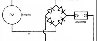
- The power supply unit, which includes capacitances C2, C5, a comparator, a transformer, and a thermoelectric diode.
- A node that delays the connection of the consumer load and consists of resistances, transistors, and capacitance.
- A rectifier bridge that measures voltage amplitude. The rectifier consists of a capacitor, a diode, a zener diode, and several dividers.
- Voltage comparator. Its components are resistances and comparators.
- Logic controller on microcircuits.
- Amplifiers, transistors VT4-12, current limiting resistors.
- LEDs as indicators.
- Optitronic keys. Each of the nicknames is equipped with triacs and resistors, as well as optosimistors.
- Electrical circuit breaker or fuse.
- Autotransformer.
Homemade apparatus
A high-quality stabilizer for several kW and an output current of more than 10 amperes can be assembled based on an old transformer installed in a welding machine. However, such a “blank” is not easy to find. Moreover, the current technology is suitable for subsequent use for its intended purpose. For reproduction at home without professional skills, the circuit presented below on electronic components is suitable. It will provide:
- prompt correction of output parameters with a switching speed of no more than 8-12 milliseconds;
- operating input voltage range 125-265 V;
- power of connected consumers up to 5.5 kW.
Electrical and wiring diagram, printed circuit board
Advantages of a homemade device
In addition to good technical parameters, the following advantages should be noted:
- reasonable costs;
- the ability to independently perform repair operations.
Flaws
The consumer parameters of the product largely depend on the assembly. In this case, it is assumed that there are no well-developed skills and professional installation (measuring) equipment. On the other hand, careful execution of individual work operations will help control quality more thoroughly than the actions of third-party contractors.
Differences from factory models
Modern production is characterized by a high level of automation. This reduces the harmful influence of the “human factor” and reduces costs. With the use of professional technologies it is easier to ensure a perfect appearance. However, when creating a homemade product, you can use unique technical and aesthetic solutions.
Accessories
Main components (functional components):
- transformer power supply with diode temperature compensation and comparator;
- rectifier with divider;
- transistor load connection delay circuit;
- controller on digital chips;
- LED indication of operating modes and emergency situations;
- keys from optitron pairs.
Features of home production
Standard transformers TPK-2-2x12V are suitable. If necessary, you can create analogs with your own hands, using PEVs with a conductor diameter of 0.064 mm (8669 turns) and 0.185 mm (522 turns) in the primary and secondary windings, respectively.
Principle of operation
How does our network voltage stabilizer, which is easy to make with your own hands, work?
After the power is turned on, capacitor C1 is in a discharged state, transistor VT2 is open, and VT2 is closed. Transistor VT3 is also closed. It is through it that current will be supplied to each LED and triac optotron.
Since this transistor is off, the LEDs are not lit, each triac is off, and the load is off. At this time, electric current passes through resistor R1 and enters C1. Next, this capacitor is charged.
The delay interval lasts only three seconds. During this time, all transient processes are carried out, and after completion, the Schmitt trigger is triggered, the basis of which is transistors VT1 and VT2.
Next, the third transistor opens and the load is turned on.
The voltage that comes out from the third winding T1 is rectified by the diode VD2 and capacitor C2. Next, the current passes through the divider R13…14. From R14, a voltage whose level is proportional to the number of volts in the network is included in each non-inverting input of the comparators.
The number of comparators is eight and they are all located on chips DA2 and DA3. At the same moment, a constant reference current enters the inverting input of each comparator. It is supplied by resistor dividers R15…23.
After this, the controller comes into play, which processes the signal at the input of each comparator.
Triac-transformer AC voltage stabilizer
In rural areas, and sometimes in cities, significant drops in mains voltage relative to the nominal 230 V often occur. This often leads to refrigerator failures. The efficiency of working with power tools decreases significantly, and the lighting dims. To stabilize the network voltage while maintaining its shape, the author at one time used a relay-transformer stabilizer [1], but from many years of use the contacts of the relays installed in it wore out. It was decided to rework the stabilizer, replacing the electromagnetic relays with triac switches. The load capacity of the proposed stabilizer is 1840 VA.
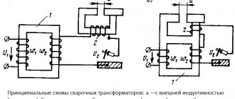
First of all, let's consider possible circuits of alternating voltage stabilizers based on an autotransformer. In the device according to the diagram shown in Fig. 1a, compensate for the decrease in mains voltage (an unacceptable excess of the nominal value is observed extremely rarely), gradually moving the moving contact of switch SA1 down the circuit. In this case, the voltage on each of the windings of the autotransformer and at the output of the stabilizer is approximately maintained, fluctuating within limited limits. In a stabilizer assembled according to the diagram in Fig. 1b, the mains voltage is constantly supplied to one of the winding taps of the autotransformer, and as the voltage in the network decreases, the moving contact of switch SA1 is moved up.
Rice. 1. Possible circuits of AC voltage stabilizers based on an autotransformer
Let's consider the main features of the above options.
In the device according to the diagram shown in Fig. 1a, the voltage on each of the winding sections is stabilized, which allows its sections II-IV to be used as stable sources of relatively small alternating voltage, for example, to power low-voltage power tools. Switching of autotransformer taps (in a real design using relays or triacs) always, even when the stabilizer is idling, occurs under an inductive or active-inductive load, which is unfavorable for switching devices.
In the device according to the diagram in Fig. 1,b the voltage on the winding sections is not stabilized. In the absence of load, and this is the main situation when working on a refrigerator, switching occurs in idle mode, the wear of the relay contacts is purely mechanical.
The selection criterion for the author was the last difference between the options.
Note that both considered options will become suitable for compensating for an increase in voltage in the network if the output (in Fig. 1, a) or input (in Fig. 1, b) wire is transferred to another tap of the autotransformer winding. In his practice, the author came across a variant of the stabilizer, the diagram of which is shown in Fig. 1, c. When the network voltage is less than or equal to the rated one, it operates in the same way as in the version in Fig. 1, a. When the voltage in the network exceeds the nominal value, the moving contact of switch SA1 is fixed in the upper position according to the diagram, and switch SA2 is moved to position 2.
Let us take as a basis the diagram shown in Fig. 1b, and determine the procedure for calculating the transformation coefficients for various positions of the SA1 switch slider. Let's set the limits for changes in the input voltage and permissible fluctuations in the output voltage. According to the results of observations at the dacha for which the described stabilizer was built, the voltage in the network sometimes dropped to 150 V. This input voltage should correspond to an output voltage of 200 V, at which all household electrical appliances still operate. Therefore, the voltage increase factor with switch SA1 in position 1 should be equal to 200/150 = 1.33. Here and further, I deliberately do not use the term “transformation ratio”, since it is understood as the ratio of the number of turns of the primary winding to the number of turns of the secondary. In this case, it is more logical to use the inverse value - the voltage increase factor.
The number of taps from the autotransformer winding depends on the required accuracy of maintaining the output voltage. As a result of several trial calculations, it was concluded that to maintain it within 210...240 V, four steps are sufficient, including direct connection of the load to the network. A decrease in the voltage in the network to 150 V is considered as an emergency in which the voltage at the load drops to 200 V.
It can be shown that in order to obtain the same limits of change in the output voltage in each position of the switch SA1, the values of the coefficients of increase in these positions must represent a geometric progression. Therefore, if in position 1 the increase coefficient is 1.33, it should be equal to 1.1 in position 3 and 1.21 in position 2. In position 4, the output voltage comes directly from the network and the coefficient is 1.
Let's plot the dependence of the output voltage on the input. To do this, on a sheet of graph paper measuring at least 250×250 mm, draw coordinate axes on a scale of 1 mm/V and draw four straight lines from the origin of coordinates with slope angles of 1; 1.1; 1.21 and 1.33. Let us select sections of these straight lines located between the horizontal lines corresponding to the output voltage of 210 and 240 V. From the points of intersection of the lines with a slope of 1.33, 1.21 and 1.1 with the horizontal of 240 V, we lower the vertical straight lines until they intersect with the nearest lines with a slope of 1.21, 1,1 and 1. From the points of intersection of these inclined lines with the horizontal 210 V, we will draw similar straight lines upward.
In Fig. Figure 2 shows a fragment of the resulting drawing. When the input voltage is more than 220 V, switch SA1 is in position 4, and the output voltage is supplied to the output without change. When the network voltage decreases to 210 V, the switch is set to position 3, the transmission coefficient increases to 1.1, and the output voltage jumps to 231 V. With a further decrease in the network voltage to approximately 191 V, the output will decrease to 210 V, the switch will be set to position 2, the output voltage will rise again to 231 V. A similar process will occur when the input voltage decreases to 173 V. When it decreases to 150 V, the output voltage, as mentioned above, will drop to 200 V.
Rice. 2. Graph of output voltage versus input voltage
When the input voltage increases, switching occurs when the input voltage reaches the values of 180, 198 and 218 V, while the output decreases abruptly each time from 240 to 218 V. Thus, when the mains voltage changes from 158 to 240 V, the output is maintained in the range from 210 to 218 V 240 V.
To prevent surges from occurring too frequently when the network voltage fluctuates around the switching thresholds, hysteresis is necessary. The described algorithm for switching winding taps provides it sufficiently. It is easy to see that while maintaining the number of stages, even a slight increase in the accuracy of maintaining the output voltage due to narrowing the hysteresis loops will lead to a significant decrease in their width, which is unacceptable. Therefore, to achieve greater accuracy, it is necessary to increase the number of steps of changing the coefficient. Note also that the reasoning for choosing its values is also valid for devices according to the circuits in Fig. 1,a and fig. 1, c.
The schematic diagram of the stabilizer is shown in Fig. 3, and the diagram of its control unit is in Fig. 4. The autotransformer is composed of three identical transformers T1-T3 - TPP319-127/220-50 [2], the primary windings of which are connected in parallel, and the series connection of the secondary windings provides the required voltage increase factors.
Rice. 3. Schematic diagram of the stabilizer
Rice. 4. Diagram of the stabilizer control unit
When switch SA1 (see Fig. 3) is set to the “Bypass” position, the input voltage is supplied directly to the output, and no components of the device, except for the voltmeter PV1 and the noise suppression circuit R2C2, consume energy from the network. This mode corresponds to the absence of output voltage stabilization. In the middle position of switch SA1, all its contacts are open, so no voltage is supplied to the output.
When switch SA1 is set to the “Stab.” The control unit begins to operate, receiving power from transformer T4 - TA1-127/220-50 [2]. The voltage from its two 6 V windings, connected in series, rectifies the VD2 bridge and stabilizes the DA2 integrated stabilizer at a level of 5 V. From the output voltage of the stabilizer, the resistive divider R7-R11 generates reference voltages for comparators DA1.2-DA1.4, supplied to their non-inverting inputs. To simplify calculations, they are taken equal to 1/100 of the voltages corresponding to the middle of the hysteresis loops in Fig. 2 - 2.14, 1.95 and 1.77 V.
A constant voltage proportional to the input is generated from the rectifier bridge VD1 coming from winding 11-12 of transformer T4. It is smoothed out by capacitor C3. A portion of this voltage, determined by the divider R5R6R15, is supplied to the inverting inputs of all comparators.
The table illustrates the logic of the device as a whole. When the mains voltage is more than 218 V, the voltage values at the inverting inputs of all comparators are higher than those at the non-inverting ones, and their outputs are set to a low logical voltage level. The signal from the output of comparator DA1.2 inverts element DD1.1 and again inverts element DD2.1. Through the emitter follower on the transistor VT1, it turns on the LED HL1 and at the same time goes to the emitting diode of the optocoupler U1. The triac VS1 opens, the mains voltage is supplied to the output of the stabilizer.
Table
| Uвx,B | Levels (H - high, L - low) at the outputs of the elements | Increase factor | LED on | Triac open | ||||||
| DA1.2 | DA1.3 | DA1.4 | DD1.1 | DD1.2 | DD1.3 | DD1.3 | ||||
| >218 | L | L | L | N | L | L | L | 1 | HL1 | VS1 |
| 198…210 | H | L | L | L | N | L | L | 1,1 | HL2 | VS2 |
| 180…191 | H | N | L | L | L | N | L | 1,21 | HL3 | VS3 |
| <173 | N | N | N | L | L | L | N | 1,33 | HL4 | VS4 |
When the mains voltage decreases, the outputs of comparators DA1.3 and DA1.4 are set to high logic levels one after another. The output signals of all comparators, converted by the simplest logical node on the “Exclusive OR” elements DD1.1-DD1.4 into a positional code, turn on the emitting diodes of triac optocouplers U2-U4 through emitter followers on transistors VT2-VT4. The optocouplers, in turn, turn on the triacs VS2-VS4, respectively, and the output voltage remains within the specified limits. With increasing voltage in the network, the described processes occur in the reverse order.
Between the outputs of the elements of the DD1 microcircuit and the inputs of the Schmitt triggers of the DD2 microcircuit, RC circuits are installed that provide a delay in the opening of the next triac relative to the moment the signal that allowed the opening of the previous one ceases. This is necessary to prevent conditions in which two triacs are open at the same time. Diodes VD4-VD7, connected in parallel with the resistors of these circuits, provide quick removal of the enabling signal from the triac optocoupler in the channel being switched off. The duration of the opening delay of photodinistors of optocouplers U1-U4, which must be guaranteed to exceed half the period of the mains voltage, can be calculated using the formula
t3 ≈ R·C·ln(Upit/(Upit - Upor)) = 330·0.047·ln(5/(5 - 3.3)) = 16.7 ms,
where R is the resistance of the delay circuit resistor, kOhm; C is the capacitance of the capacitor of this circuit, μF; Upit=5 V - supply voltage; Uthr = 3.3 V - typical threshold voltage of the Schmitt trigger of the HCF4093B microcircuit when the input voltage at the combined inputs increases. According to the passport data of this microcircuit, its spread of ±0.7 V is allowed, therefore, with the indicated values of resistors and capacitors, the delay can range from 12 to 24 ms. If we assume that the real spread is half as much, the delay will be in the range from 14 to 20 ms, which is more acceptable, but requires control when setting up the device.
To prevent the simultaneous activation of several triacs during transient processes following the moment the mains voltage is applied, a delay unit was introduced on the DA3 undervoltage detector. At the moment the mains voltage is applied, capacitor C10 is discharged, due to diode VD3, transistor VT5 is closed and the voltage at its emitter is close to zero. The emitting diodes of optocouplers U1-U4 are turned off.
When the voltage on capacitor C10 reaches a value of about 1 V, the DA3 microcircuit starts working, its output transistor opens, and the output voltage becomes zero. It remains this way until the voltage on capacitor C10 reaches 4.2 V, which takes about 200 ms, which is enough to complete the transient processes. At this moment, the output transistor of the DA3 microcircuit will be closed, and the voltage at the base and emitter of the VT5 transistor will increase abruptly to close to the supply voltage. The optocouplers will work, the required triac will be opened.
During welding work, strong voltage fluctuations occur in the network, which lead, unless special measures are taken, to very frequent switching of triacs. To combat this phenomenon, the discharge time constant for capacitor C3 was chosen to be quite large - about 8 s. As a result, when the input voltage sharply decreases, the transition to the next stage occurs in approximately 1 s, and short-term dips in the input voltage do not cause switching. At the same time, the charging time constant for capacitor C3 is small, and with an increase in the network voltage, the switching will occur almost instantly. This method of “fighting welding” is much simpler than that used in [3] and is more effective, since the stabilizer does not turn off completely, but continues to react to an increase in voltage in the network.
The stabilizer diagram (see Fig. 3) also shows the connection to the contact windings of the XS1 connector, which allows it to be used to power various low-voltage consumers. The secondary windings of the TPP319-127/220-50 transformers are designed for a current of 8 A, which determines the maximum load power of the stabilizer indicated in the sidebar to the article. However, it should be noted that it also depends on the properties of switch SA1, which should allow switching the specified current.
You can make an autotransformer for a stabilizer yourself, using one or more power transformers from tube TVs as a basis [4-6]. Such transformers have designations consisting of the letters TC, a hyphen and a number corresponding to its power in watts.
Such a transformer, after rewinding the secondary windings, will be able to provide an output current of the stabilizer equal to the quotient of its power divided by the total voltage of all the necessary secondary windings (23 + 25.3 + 27.6 » 76 V). And by the output current you can determine the maximum load power of the stabilizer.
For example, when using two TS-200 transformers with a total power of 400 W, the permissible output current is up to 400/76 = 5.26 A, and the maximum load power (with an output voltage equal to the rated voltage in the network) is 230 × 5.26 = 1210 W. Thus, the maximum load power of the stabilizer will be three times the total power of the transformers used.
The secondary windings on transformers should be carefully wound (they are usually wound over the halves of the primary), counting the number of turns of the incandescent winding Nm wound with the thickest wire. The voltage of this winding under load is 6.3 V, therefore, for the secondary winding at voltage U, the number of turns Nu can be found using the formula
NU = Nн·U/6.3.
If the transformer's magnetic core is U-shaped (like the TS-200-2 transformer), each section of the secondary winding should be divided into two equal parts, wound them on different cores of the transformer's magnetic core and connected the halves in series accordingly. With an antiphase connection, the total voltage will be zero, and it will be necessary to swap the terminals of either half.
With three transformers, to simplify it, you can wind one of the secondary windings on each. If you intend to use transformers of different powers, the least powerful one should have a winding with the lowest voltage, and the most powerful one should be wound with the highest voltage.
The halves of the primary windings (on different cores) should also be connected accordingly. Be sure to connect the manufactured transformer to the network for the first time through a fuse link. If the halves of the primary winding are connected incorrectly, it will save you from a possible fire.
The diameter of the wire of the secondary windings d in millimeters (without insulation) can be found using the formula
d = 0.7·√I,
where I is the secondary winding current, A.
The most durable insulation is found in the PEV-2 winding wire; wire in PELSHO silk insulation is also convenient. The winding is wound carefully, turn to turn, the layers are insulated between each other with pads made of writing paper. After winding, you need to assemble the magnetic circuit as it was assembled earlier, and carefully tighten it with screws or a clip - this will reduce the hum.
Most of the stabilizer elements are mounted on a printed circuit board measuring 120×85 mm, the drawing of which and the arrangement of elements on it are shown in Fig. 5. All holes in the board are located on a 2.5x2.5 mm grid. To connect circuits external to the board, contact pins from 2RM series connectors are soldered into it. The diameter of the pins is 1.5 mm for triac circuits and 1 mm for the rest. Sockets from the same connectors are soldered to the wires connected to them. The color of the wires corresponds to that indicated in the diagrams in Fig. 3 and fig. 4, and the contact pins for them are marked with pieces of heat-shrinkable tubing of the corresponding color.
Rice. 5. Drawing of the printed circuit board and arrangement of elements on it
The board contains imported oxide capacitors - analogues of K50-35. Capacitors C15-C18 (as well as C1 and C2 in Fig. 3) are metal film K73-17. It is not advisable to use ceramic capacitors C11 - C14, especially if you plan to use a stabilizer at sub-zero temperatures. K73-17 capacitors are also suitable here, which are much more thermally stable than ceramic capacitors of equal capacity.
The HCF4093BEY chip can be replaced with another 4093, 4093B in a DIP14 package or a K561TL1 chip, and the LM324N quad op-amp can be replaced with a K1446UD3 or K1401UD2. In the latter case, you need to keep in mind that the power pins of the K1401UD2 microcircuit are located in a mirror with respect to the LM324N microcircuit. Therefore, when installing the K1401UD2 microcircuit on a board, it should be rotated 180° without changing the pattern of printed conductors. When using the K1446UD3 microcircuit, the resistance of resistors R12-R14 should be reduced by approximately 20% to maintain the width of the hysteresis loops. The fact is that the op-amp of the K1446UD3 microcircuit belongs to the rail-to-rail class, where the maximum and minimum output voltage levels are equal to the potentials of the positive and negative power terminals, respectively. As a result, the output voltage range is slightly larger than that of the op-amp of the LM324N and K1401UD2 microcircuits.
The KR1171SP42 undervoltage detector can be replaced with MCP100-450, MCP100-460 or MCP100-475 [7]. Instead of the KT3102GM transistor, it is permissible to install the KT3102EM. Rectifier bridges VD1, VD2, diodes VD3-VD7 - any small-sized silicon ones. Resistors R12-R18 should be used with a tolerance of at least ±5%.
It is interesting that in the design under consideration, the set of “Exclusive OR” elements K561LP2 can be replaced by the decoder K561ID1. Inputs 1, 2, 4 of the decoder should be connected to the outputs of the comparators, and outputs 0, 1, 3, 7 - to the delay circuits.
It is not advisable to replace BTA16-600BW triacs with others. The W index in their designation means that these triacs allow an increased rate of voltage rise between the main electrodes without leaving the closed state. In addition, triacs of this series have a metal heat sink flange completely isolated from all electrodes, which allows them to be installed on a heat sink that is not isolated from the stabilizer housing. If you use triacs, the flange of which is connected to electrode 2, you should isolate their common heat sink from the stabilizer housing.
MOS3043M thyristor optocouplers are being replaced by similar ones that have a built-in unit that guarantees the opening of the triac at the moment the instantaneous value of the voltage applied to it passes through zero [8]. If the optocouplers used are opened by a control current greater than 5 mA, it is necessary to change the resistance of resistors R29-R32 in inverse proportion to the required current.
Experience has shown that the installation of damping RC circuits (for example, R41C15) is required more for optocouplers than for triacs. Recommendations for choosing the parameters of these circuits are given in [8] and [9].
Digital alternating voltage voltmeter PV1 - ready-made imported, purchased in an online store. Measured voltage with a frequency of 50 Hz - from 70 to 500 V, error - ± 1%, dimensions - 48x22x29 mm.
Transformer T4 can be eliminated if you use instead a diode bridge rectifier VD2 and a voltage stabilizer DA2, a ready-made stabilized mains voltage converter to DC 5 V. A cell phone charger may be suitable here. However, it should be borne in mind that the stability of the output voltage of chargers is usually low, and it itself slightly exceeds 5 V. It is necessary to make sure that this voltage practically does not change when a resistor with a resistance of 50 ... 100 Ohms is connected to the output of the charger and when the voltage changes in a network from 120 to 250 V. If this is not the case, a 5 V voltage stabilizer microcircuit with a low voltage drop between input and output (the so-called low drop stabilizer), for example, LM2931Z-5.0 or KR1158EN5 with any letter index should be installed at the output of the charger .
If you exclude transformer T4, instead of a voltage of 28 V, you need to apply mains voltage to bridge VD1, and increase the resistance of resistors R3, R5, R6 approximately eight times. Install capacitor C3 with a capacity of 3.3 μF for a voltage of 400 V. It should be borne in mind that as a result of these alterations, all elements of the stabilizer will be under mains voltage.
Transformers T1 -T3 are fixed between two metal pallets measuring 387x177x20 mm from disassembled EC computer devices. On the front, according to Fig. 6, the tray contains a switch SA1, a voltmeter PV1, a fuse holder FU1, LEDs HL1-HL4, two pairs of output sockets XS2, XS3 and a 12-pin connector XS1 ШР32П12НГ3 for connecting low-voltage consumers. The T4 transformer is mounted on the rear tray.
Rice. 6. Installation of the device
An aluminum block with a cross section of 10×25 mm was used as a heat sink for the triacs, serving as a spacer connecting the pallets. It conducts heat from the triacs to the housing. A printed circuit board is attached to the same rack and another similar one. The triac leads should be soldered to the contact pads on the printed circuit board only after installing the triacs on the heat sink to which the printed circuit board is attached.
When setting up a stabilizer, you should first connect only transformer T4 to the network and set the voltage on the trimmer resistor motors R8-R10 to 2.14, respectively; 1.95 and 1.77 V relative to the common wire, and on resistor R15 - 1/100 of the current network voltage value. Using a laboratory autotransformer (LATR), check the order in which LEDs HL1-HL4 are turned on in accordance with the table given earlier. The switching thresholds of the voltage increase coefficients must correspond to those indicated in the description of Fig. 2. If necessary, you can more precisely adjust the switching thresholds using trimming resistors R8-R10, and to change the width of the hysteresis loop of a comparator, select its input resistor (R12-R14). The width of this loop is directly proportional to the resistance of the corresponding resistor.
It is advisable to check the serviceability of the triac opening delay circuits (elements R20-R23, C11 - C14, VD4-VD7) by disconnecting bridge VD1 from transformer T4 and connecting to the connection point of resistors R6 and R15 the circuit whose diagram is shown in Fig. 7. When switch SA2 is closed, the voltage on capacitor C19 smoothly increases from zero to 2.5 V, when open, it drops to zero. You should check with an oscilloscope with a waiting sweep the presence of a delay in the falling pulse edge at the output of each Schmitt trigger (DD2.1 - DD2.4) relative to the rising pulse edge at the output of the corresponding "Exclusive OR" element (DD1.1-DD1.4). On the oscillogram Fig. 8, where the scan rate is 2 ms/div., this delay is 15.5 ms with acceptable limits of 14...20 ms.
Rice. 7. Circuit diagram
Rice. 8. Oscillogram
After this, you can restore the connection of the triacs to the transformers (before the first turn on, install a 5 A fuse-link in the electrode circuit 2 of each triac), connect a load with a power of 100...200 W and check the one shown in Fig. 2 dependence of the output voltage on the input. When using the stabilizer, you can quickly adjust the interval of change in the output voltage using trimming resistor R6, for example, set it to 200...230 V.
Useful tips on the design of the stabilizer to ensure its fire safety can be found in [3].
Both when setting up and during operation of the stabilizer, it should be remembered that when the voltage in the network sharply decreases, switching of the stabilizer occurs with a very noticeable delay - about a second for each step.
Literature
1. Biryukov S. Relay-transformer alternating voltage stabilizer. — Circuitry, 2003, No. 7, p. 26-28.
2. Sidorov I. N., Mukoseev V. V., Khristinin A. A. Small-sized transformers and chokes. Directory. - M.: Radio and Communications, 1985.
3. Mayorov M. Mains voltage stabilizer for a refrigerator. — Circuitry, 2002, No. 2, p. 53-59.
4. Kuzinets L. M., Sokolov V. S. Television receiver units. - M.: Radio and Communications, 1987.
5. Sidorov I. N., Binnatov M. F., Vasiliev E. A. Power supply devices for household electronic equipment. - M.: Radio and Communications, 1991.
6. Sidorov I. N., Skornyakov S. V. Transformers of household radio-electronic equipment. Directory. - M.: Radio and Communications, 1994.
7. Potapchuk M. Supervisors of the MCP10X series from Microchip. — Circuitry, 2006, No. 1, p. 10, 11.
8. MOC3031M, MOC3032M, MOC3033M, MOC3041M, MOC3042M, MOC3043M 6-Pin DIP Zero-Cross Optoisolators Triac Driver Output (250/400 Volt Peak). — URL: https://www. farnell.com/datasheets/1639837.pdf (12/12/17).
9. Nikolaychuk O. Load control on alternating current. — Circuitry, 2003, No. 4, p. 25, 26.
Author: S. Biryukov, Moscow