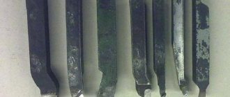
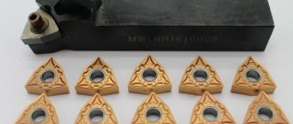
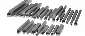
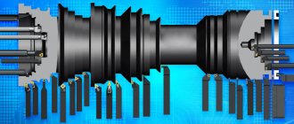
Types and purpose of scoring cutters
Purpose of the tool:
- remove allowance on cylindrical or conical workpieces;
- make chamfers;
- cut ledges at different angles (straight or sharp);
- grind the ends;
- grind off excess elements on the workpiece.
Work with such a tool is carried out for roughing, semi-finishing and finishing. In the process of carrying out the necessary operation, the cutting tool is installed in a lathe, in a device specially designed for such purposes, and is rigidly attached. In the process of moving, it crashes the working part into the metal by a selected amount and, deforming, breaks it off in the form of chips. Scoring cutters operate with transverse or longitudinal feed. They are distinguished, and therefore classified, depending on the following factors:
- manufacturing method (solid, composite);
- type of processing (finishing, roughing);
- feed directions (right, left);
- designs (straight, bent, persistent).
Solid products are made from one grade of metal, composite products are made from different grades of steel. This comes from the requirements that apply to the components of the scoring cutter. The holder must be made of durable and wear-resistant metal that can withstand impacts well. The working head is made of a material that has the same properties, but one more requirement is added to them: the material should not heat up during the grinding process.
Depending on the design, a scoring cutter can provide work with varying degrees of cleanliness and roughness, which affects the type of processing. In some cases, the workpiece is initially rough processed. Then the cutting tool is changed and finishing is performed with it.
Determine the feeding direction in this way: place your palm on the tool and look at the direction of your thumb. The figure clearly shows how to determine the through cutter in the feed direction:
In the design of a straight scoring cutter, the cutting edges are located parallel to the fastening rod (holder). For a bent scoring tool, they are tilted to one side of the axis (left or right). For a thrust-type product, the cutting edges are located at an angle, which most often does not exceed 100°.
The best product manufacturers are companies from Germany GI (Kraft), Czech Republic (Proma); Switzerland (Zenitech).
Types of cutters for a lathe and their purpose
When describing the types of turning tools, several classifying characteristics are usually used. According to its design, it is divided into two types: solid and prefabricated. In the first case, the entire product is made in the form of a monolithic bar of metal. And in the second, removable or soldered carbide plates act as the blade. According to their technological purpose, turning cutters are divided into special ones, which are used for processing various profiles and threading, and general purpose products, used for external and internal turning, cutting and end trimming. Another distinguishing feature of a turning tool is the configuration of the cutting part, which depends on its operating modes and the type of turning work. For turning hard-to-reach places, a curved cutter is usually used, which has several varieties, differing in the length of the cutting part, the shape of the bend, sharpening and purpose (cockerel, bent, reverse cutters and others).
Another classification option is the division of turning tools according to the principle of machining cleanliness. There are usually two classes here: rough and finishing. The first is intended for roughing or pre-turning operations, and the second is for finishing operations. If the rough tool, with rare exceptions, is quite the same type, then among the finishing tools there are a number of varieties with their own names. Examples include blade and radius cutters with an arcuate blade, the purpose of which is precise finishing turning. Another separate type is a diamond cutter, used for turning work on super-hard materials. A cup turning cutter with a circular cutting surface has a unique design that can work for a long time without regrinding.
In addition to the standard classification, there are many names for specific turning tools, usually reflecting the features of its design or technology of use. These include a spring cutter with a wave-shaped cutting part, which springs during turning of hard and uneven materials.
A separate category of cutting tools for lathes are planing cutters. During turning operations using them, feed is carried out on a stationary part. In this case, the allowance is not cut off, as during rotation, but is removed by planing. In this configuration, a lathe performs the same function as a planer or slotter.
Pass-through straight, bent and persistent
The most common turning operation is turning the outer parts of cylindrical workpieces. In this case, three basic types of cutting tools are used, shown in the figure below.
The thrust cutting tool is designed for turning long and non-rigid products, since its design contributes to less bending of the part. The bent cutter has a blade located at an angle to the holder, so it can be used for longitudinal feed. All cutters of this type are fixed in the tool holder so that their tip is opposite the main axis of rotation of the machine. One of the varieties of the straight type is a spring cutter, which has an elongated and curved cutting part that springs during processing. The through-cutting tool is the most widespread and universal, therefore it is often made non-separable from high-speed tool steel.
Scoring cutters
The main purpose of this tool is to trim ends and form ledges on rotating workpieces. Scoring cutters work in both feed directions and can therefore form shoulders at different angles. Structurally, these are most often prefabricated high-speed cutters. The photo below shows trimming the end of a bronze blank.
Read also: The technological process of data processing consists of
Parting cutters
This type of turning tool belongs to the group of grooving and cutting tools. It is distinguished from pass-through and scoring cutters by the specific shape of the cutting part. On its blade, on the sides of the main working edge, there are two auxiliary grooves that ensure cutting of the side planes of the groove. In addition, to reduce friction on the side surfaces of the groove being cut, the cutting part has a trapezoidal shape with a narrowing towards the holder. The head of such a tool, as a rule, has a reinforced shape, often curved upward (the so-called cockerel incisor). It is recommended to cut off as close to the chuck as possible, with the cutting edge positioned exactly against the axis of rotation and the tool body strictly perpendicular to the cutting plane. Cutting work is performed at lower speeds than turning, and when cutting steel and hard metals, coolant must be supplied to the processing zone. The photo below shows a segment.
Threading internal and external cutters
If turning requires high precision in the relationship between the thread axis and other planes of the product, then in this case it is recommended to use thread-cutting tools. The technology of applying threads with a cutting tool is based on the exact correspondence of the geometric parameters of its cutting part and the threaded profile of the product. Regardless of the type of thread, during such operations the feed must be synchronized with the spindle speed. Structurally, the cutting tool used for external threads is straight, and for internal threads it is bent. The photo below shows external thread cutting.
Boring cutters
This type of tool is designed for turning internal cylindrical surfaces in order to achieve precise alignment with the axis of rotation of the part. When turning boring, chip removal, heat removal and the use of coolant are difficult, so the tool is in more difficult conditions than when performing external turning. As a result, such turning is performed at lower speeds and shallow depths. There are two main types of cutting boring tools: thrust and through. The former are intended for dead-end holes, and the latter for through holes. For boring large diameters, tool holders of various configurations are usually used, which can also accommodate boring cutters. The photo below shows a boring.
Prefabricated tool
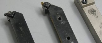
Structurally, turning cutters are produced in two main varieties: all-metal and prefabricated. In the first case, the entire product is made of a single metal bar, at the end of which the blade is sharpened. In the second, everything is all-metal except the blade, which in such a product is a cutting plate fixed at the end of the tool head. The cutting inserts in this type of turning tool can be attached by soldering or mechanically. In the first case, it is fixed by soldering or welding, and in the second - by various mechanical devices, among which the most common are threaded elements, clamps and eccentrics. Tips and inserts for cutters are made from special cutting materials, the main ones being tool steel, hard alloys and powder composite materials.
Geometric parameters
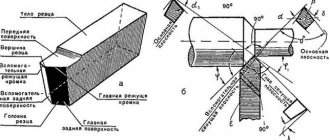
Structurally, the product consists of a cutting part (called the head) and a rod (body), with which the tool is secured to the lathe. This part is called the holder. Using the working head, the necessary planes are formed in a workpiece made of ferrous and non-ferrous metals. It distinguishes the following structural elements:
- top;
- surfaces: main, front and back;
- main and auxiliary edges.
The sharpening angles are also distinguished. The tool differs in type, manufacturing method, geometric dimensions of the holder, and the length of the entire product.
How to install a cutter on a machine
The turning tool is mounted on the carriage of the movable support using a single or multi-position tool holder. To correctly install the cutter, it must be accurately aligned relative to the main axis of the machine in the perpendicular and parallel directions. The cutting edge of most turning tools must be strictly opposite the axis of rotation, which requires the tool to be adjusted in height. To do this, they usually use mild steel plates of different thicknesses, which are placed under its base. An important installation condition is also the rigid fixation of the cutter, so it must be clamped without backlash or gaps.
If any of the readers have experience working on a lathe, please tell me how many turning tools and what type should be available in a home workshop. We look forward to your response in the comments to this article.
Markings used
The quality of purchased scoring cutters must meet the requirements specified in GOST 18871-73, 18880-73, 28980-91, 29132-91 and the technical specifications of manufacturing companies, if they are manufactured according to such a document.
These standards indicate the design features of products, differences in geometry and dimensions. The marking of scoring cutters depends on their type. The table shows the marking features
| Type of turning scoring tools | Components of the designation | An example of a symbol and its explanation |
| End with high-speed steel plates | Type in the direction of supply, taking into account the cross-section, length and GOST | Cutter 2112-0038 GOST 18871-73, where: 2112-0038 – left cutter with a holder section of 32x20 mm and a length of 170 mm, produced in accordance with GOST 18871-73 |
| Bent with carbide inserts | Type in feed direction, cross-section, plate material and GOST | Cutter 2112-0007 VK6 GOST 18880-73, where: 2112-0007 – right cutter with a holder section of 25x16 mm with a plate made of VK5 material, produced in accordance with GOST 18880-73 |
| With replaceable cutting inserts made from ultra-hard materials | Type in the direction of supply, taking into account the cross-section, length and GOST | Cutter 2110-2395 GOST 28980-91, where: 2110-2395 – right cutter with a cross-section of 32x32, with a cutting part length of no more than 25 mm, with a cutting plate SNUN-050304, produced in accordance with GOST 28890-91 |
| Feedthroughs with replaceable polyhedral plates | Symbol according to GOST 26476-85 |
Classification
According to the design and principle of operation, this tool is differentiated into the following options:
- Straight models with cutting edges parallel to the holder axis are characterized by the absence of bends. They are designed for rough processing, which involves removing a significant amount of material, often in several passes, when turning unnecessary fragments of parts.
- Bent scoring cutters have a similar purpose, but are designed for processing objects of more complex shapes: bending allows you to grind hard-to-reach places, etc. The cutting edges of such models are inclined from the axis of the holder. The method of work is determined by the characteristics of the tool and the type and thickness of the material.
- Turning stop options are designed for turning objects of low rigidity. They are used for trimming edges and turning stepped surfaces. This is the most common type of instrument considered. Their cutting edges are parallel to the holder axis, however, in comparison with straight scoring cutters, they have a smaller angle.
Based on the feeding direction, these tools are classified into left-handed and right-handed.
Finally, scoring cutters are differentiated according to production technology.
- One-piece options include head and holder made from the same material.
- Composite models have elements of different composition.
The parameters of the instruments under consideration are regulated by GOSTs.
Thus, bent scoring cutters with carbide cutting inserts are described by GOST 18880-73. For turning cutters equipped with super-carbide inserts, and similar scoring models, the characteristics are defined in GOST 28990-91. GOST 18871-73 defines the features of end options with high-speed steel plates. GOST 29132-91 defines the parameters of models with multifaceted replaceable inserts of the through-turning, copying and scoring types. GOSTs provide drawings of scoring cutters, types and sizes of these tools.
Download GOST 18871-73
Download GOST 18880-73
Download GOST 29132-91
Features and Benefits of Insert Scoring Tools
Products with plates made of hard alloys are the most popular. The presence of plates made of special steels (high-speed or with cobalt in the composition) makes the product wear-resistant, extends its service life, and, in addition, reduces the cost of its production. Inserts for such scoring cutters are made from alloys T5K6, T5K10 or high-speed steel grades, such as R9K5, R9K5F2, for processing workpieces made of hard and alloy steel grades. Work on workpieces made of soft material (iron, cast iron, etc.) is performed with cutters with plates that contain, in addition to cobalt, tungsten (VK6, VK8, VK10, VK6V, VK3M). This is indicated in the passport data and symbol.
Selection of scoring tool
The choice of the required type of cutting tool is carried out taking into account the grade of the metal being processed, the design features of the future part and the characteristics of dimensions, roughness and surface cleanliness. All this data is indicated on the design drawings of the part. The cutting process, as already indicated, occurs using longitudinal and transverse feeds, while it is necessary to remember the basics of cutting:
- roughing is performed to a depth of no more than 5.0 mm with a transverse feed of no more than 0.7 mm per revolution;
- Finishing is performed to a depth of no more than 1.0 mm per revolution with a transverse feed of no more than 0.3 mm per revolution.
The video shows the process of cutting with a pass and with ledges using scoring cutters and talks about their design features:
We ask those who have cut different grades of metals on lathes using a scoring cutting tool to share their experience and tell us in the comments about the nuances of the work.
