When carrying out installation or repair work, it often becomes necessary to find out the diameter of a pipe that is located in an inconvenient place - for example, at the bottom of a pit. Moreover, the pipe itself is additionally recessed into the protective casing. Such situations may arise when replacing old pipes with new ones in sewerage, heating or water supply systems. Almost always by this time the old documentation used for installation cannot be found.
At first glance, the task of determining the pipe diameter seems simple. But special technical devices are not always at hand. We will tell you how, with the necessary skills, you can use what is almost always at hand. So, to accurately determine the pipe diameter, we may need:
- lace, thread, piece of thin rope
- camera, camera phone
- an object with known dimensions (box of matches, pack of cigarettes, etc.)
- ruler, tape measure
- calipers
- calculator
Of course, if there is free and convenient access to the pipe, then a caliper is enough to find out in a couple of seconds, and with maximum accuracy, the diameter of the pipe. You can immediately accurately measure not only the outer diameter, but also the inner diameter and wall thickness of the pipe. But even if you measure only the outer diameter and wall thickness, it is easy to calculate the inner diameter of the pipe using a calculator.
measuring pipe diameter with a caliper
Next, we will consider a common dacha situation, when at the right moment there was no special measuring tool such as a caliper or laser rangefinder at hand. Or when the pipe is located so inconveniently that it is impossible to get to it with a long caliper and laser.
So, we measure the diameter of the pipe using a string (thread, thin rope). Carefully, with a slight tension, so that there is no sagging, we wrap the lace around the end of the pipe. We mark the point of contact between the ends of the lace, cut off a fragment of the lace, straighten it and apply it to the ruler. We found out the circumference of the pipe section. Now, using a simple school formula, we find out the diameter: divide the circumference by 3.14. The method seems not very accurate, but this is not entirely true. The industry produces a standardized range of sewer, water and other pipes, whose diameters change through a certain step and are well known. Even if you don’t know the diameter of the pipe very precisely, you can easily find its correspondence in the manufactured product using the table.
special ruler for measuring diameters
If the pipe is located quite conveniently for measurement, but there is no caliper on our list, you can measure the diameter of the pipe using a ruler or tape measure. The accuracy will be higher than when measuring with a string or thread, but lower than with a caliper. It will not be difficult to clarify the actual diameter of the pipe, as described in the paragraph above.
Let's consider the most difficult case - you cannot reach the end of the pipe either with a caliper, or a ruler, or a cord. Fortunately, today almost everyone has a phone with a camera, which cannot be said about a caliper. We apply to the pipe or place next to it an object whose dimensions we know. For example, this is a box of matches. We take pictures. Next, we print out the photo or use a ruler to measure the sizes of the photographed objects directly on the monitor screen and compare them. The main thing when photographing is to place the object in the same plane as the pipe cross-section. As mentioned above, the lack of accuracy of this method is compensated by the limited number of diameters of produced pipes. Having calculated the approximate diameter of a sewer or water pipe from a photograph, all that remains is to select the closest pipe from the directory.
Information about pipe diameters
Often for standardized pipes produced by industry, the diameter is indicated in inches. To convert inches to the more familiar values of the International Metric System SI (meters, kilograms, seconds, etc.), you need to multiply the size indicated in inches by 2.54 mm. That is, 1 inch = 2.54 mm, or 1 cm = 0.398 inches.
parameters of water and gas pipes
In order not to make a mistake when choosing pipes, it is necessary to clarify an important detail. When they say “I need a 1-inch water pipe,” they do not mean the outer diameter of the pipe, or even the inner one - but the so-called nominal diameter of the pipe, which is closer in value to the inner diameter. In order to provide a more accurate choice for designers and installers, there are special tables where the conditional, nominal, external and internal diameters of pipes can be indicated.
Accurate knowledge of the pipe diameter is necessary to correctly calculate the pipeline capacity with a known performance of the supply pump or other source. For example, the calculation of water supply and sewerage, heating in a country house takes into account the exact technical parameters of the pipes used.
www.avtonomno.ru
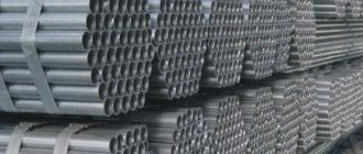
Metal products and their outer diameters
All types of metal pipes are manufactured at the factory, based on their outer diameter “Dн”. Standard diameters are shown in the table below.
In industry and construction, they mainly use products whose diameters are in the range of 426–1420 mm. Intermediate standard sizes of water pipes are taken from the table.
Small D metal products are mainly used for laying water pipes in residential buildings.
Medium D metal pipelines are used for laying city water supply. Such water pipes are used by industrial systems involved in the extraction of crude oil.
Large sizes of steel pipelines have found application in the creation and laying of main oil pipelines. They are also used in the gas industry. Through such pipelines gas is supplied to every corner of the planet.
Outer diameter of pipes (Dн): classification of steel products
As mentioned above, the inner and outer diameters are different from each other. The first of them is used to designate individual elements of pipeline structures. Sales of steel products are also carried out by internal diameter. This indicator is important if it is necessary to carry out installation calculations for a water supply or gas line. In turn, the outer diameter is used to determine the strength characteristics of the pipeline and its resistance to mechanical loads.
The outer diameter allows you to determine the strength of the pipe and its resistance to damage
The outer diameter of steel pipes is a characteristic by which all products made from this material are classified. Depending on this parameter, there are three main types of pipelines:
- small;
- average;
- big.
Pipes that belong to the small group have a diameter range from 10 to 102 mm. Medium-sized products can have a cross-section from 102 to 426 mm. The diameter range of large steel pipes starts from 426 mm. In turn, it is recommended to determine the internal diameter using the table.
Small pipes are used when installing communications in residential buildings. Medium-sized products are used to lay urban water transportation lines, and they are also actively exploited by companies engaged in oil (crude) production. The main areas in which large steel products are used are oil and gas transportation areas. Trunk lines are assembled from large parts. The diameter of gas pipes can reach 1220 mm.
The range of steel pipes is quite wide, since these products are used in all areas where laying communications is required
Standard diameters of steel pipes: table and description
When finding the internal diameter, the indicator corresponding to the dimensions of the nominal diameter is rounded to 0 or 5. Thus, when determining this characteristic, the size is standardized to the nearest parameter of the metric system.
Related article:
GOST standards for steel pipes: basic standards for quality products. Different types of metal products. Types of pipes. Manufacturing methods. Technical characteristics of steel pipes according to the standard.
Knowing this information, it is easier to calculate the pipe diameter. How this parameter is measured in millimeters and inches has already been mentioned above.
Note! The most widespread, due to their operational suitability, are products with a diameter from 426 to 1220 mm. These steel pipes are used as main lines for gas and oil pipelines, sewers, as well as structures used for irrigation of fields.
In residential buildings, steel water pipes are used, the diameter of which is 15 or 20 mm (sometimes 32). For sewerage, larger products are used, which is due to the need to drain wastewater. Heating systems consist of small pipes.
Table 2. Influence of diameter on operational scope:
| Operational area | Diameter, mm |
| Water pipelines in residential buildings | 15-32 |
| Gas pipelines in residential buildings | |
| Sewage systems | 50-100 |
| Gas and oil transportation lines | 426-1220 |
Regulatory documents contain more detailed tables, which contain information not only about the section, but also about other geometric characteristics. Using them, it is easiest to determine the diameter of the pipes (in millimeters and inches). It is important to remember that by using special tables you can calculate the required cross-sectional indicator (internal or external) of both steel and other types of pipes.
Finding the diameter of steel pipes: GOST table with thicknesses
The use of special tables located in the regulatory documentation allows you to very quickly determine the required parameter. This can be the internal or external diameter, and auxiliary geometric characteristics such as wall thickness, weight, etc. are also indicated.
It is worth noting that the difference between the outer diameter of metal pipes and Dу can reach 7 mm (depending on the type of rolled metal). For example, steel electric-welded parts used in the installation of utility communications may differ in these indicators by 5-10 mm.
Table 3. Diameters and thickness of electric-welded steel pipes:
| Inner diameter (Dу), mm | Outer diameter, (Dн) mm | Wall thickness, mm |
| 80 | 89 | 3 |
| 15 | 20-22 | 1,5 |
| 50 | 57 | 3 |
| 100 | 108 | 3,5 |
| 32 | 42 | 2 |
| 20 | 25-28 | 1,5-2 |
| 40 | 48 | 3 |
| 25 | 30-32 | 2 |
The main indicator indicating the identity of the product is, of course, the internal diameter. Pipes are also designated by the external cross-sectional value, which is a necessary condition when calculating mechanical resistance.
Note! The dimensions of products with inch markings are most easily determined using the tabular method. It is important to remember that when connecting lines made of steel with pipelines made of another material (for example, plastic), it is necessary to take into account not only Dу, but also Dн.
The popularity of the tabular method is due to the fact that combined pipeline structures are common in the modern world. Such systems contain steel pipes and polymer elements (fittings).
Large-diameter pipes are used to lay gas, sewer and oil pipelines
Inner diameter
This metal pipe size (Din) can have different values. Moreover, the value of external D always remains unchanged. To standardize the diameter of water supply pipes, designers use a special value called “nominal diameter”. This diameter has its own designation Dу.
In fact, the nominal diameter is the minimum value of the internal diameter of a given product, rounded to the nearest whole number. Rounding is always performed towards the maximum value only. The value of conditional D is regulated by GOST 355–52.
To calculate internal D, a special formula is used:
Din = Dn – 2S.
The internal diameters of steel products range from 6 to 200 millimeters. All intermediate values are shown in the corresponding table.
The diameter of metal pipes is also measured in inches, which is 25.4 millimeters. The table below shows the product diameters in both inches and millimeters.
Pipe diameter measurement systems: table (inches and millimeters)
Products whose diameter is measured in inches (for example, 5″) are used when laying water supply lines and gas transmission structures. On the Internet you can find tables containing this value in both millimeters and inches. Some of the schemes combine both measurement systems, which is very convenient. A five-inch pipe corresponds to a standard internal diameter of 125 mm.
Measuring the diameter of pipes in inches is used during the installation of water and gas transmission lines, as this simplifies the overall calculation. One inch is equal to 25.4 mm. It is important to remember that when measuring a pipe, 1 inch has a different size, namely 33.5 mm. This is explained quite simply: pipe dimensions are calculated by the internal diameter, and not by the external one. When drawing up the installation plan and diagram, it is necessary to take this discrepancy into account. Such information allows you to answer the question of how to measure the diameter of a pipe and avoid making mistakes.
Table 1. Dу in millimeters and inch system for designating the sizes of steel pipes:
| Dу, mm | Thread diameter, inches |
| 150 | 6″ |
| 40 | 1 1/2″ |
| 80 | 3″ |
| 15 | 1/2″ |
| 100 | 4″ |
| 32 | 1 1/4″ |
| 50 | 2″ |
| 125 | 5″ |
| 25 | 1″ |
Helpful information! As a rule, no problems arise when installing only steel products, since they are measured in inches. However, when it becomes necessary to replace the old steel communication with plastic, confusion can occur. Therefore, it is worth remembering that the actual and metric inch sizes are different.
In most cases, laying inch pipes does not cause any difficulties. The nature of the discrepancy lies in the designation of steel products (water and gas), which are sold and marked with a nominal diameter, while their actual cross-section has different dimensions. As an example, we can give a simple calculation of the dimensions of a pipe whose outer diameter is 140 mm and wall thickness is 5.5 mm.
To avoid mistakes when planning communications, it is necessary to take into account both the external and internal diameter of the pipes
To determine the actual diameter, a simple equation is used:
D = Dн – t x 2
After introducing the required values, this formula takes on the following form: D = 140 – 5.5 x 2 = 129 mm. This indicator corresponds to the actual diameter of the pipe, whose outer wall cross-section is 140 mm. However, the nominal bore or internal diameter of an inch pipe (or millimeter) is the dominant value. In this case, this value is 125 mm, which is what most construction calculations are made on.
To connect steel and plastic pipes, special transition elements - fittings - are used. Such adapters allow you to connect two pipes with different cross-sections, made of different materials. In order not to make mistakes when installing communications or replacing them, it is recommended to take into account both the external and internal diameters of steel pipes.
Plastic
Nowadays, their plastic counterparts have become an alternative to metal pipes. Moreover, their sizes vary widely. The material for such a product is:
- Polypropylene;
- Polyethylene;
- Metal-plastic.
Each manufacturer of such pipes sets its own size chart. Therefore, if one system is being manufactured, it is advisable to use parts from the same manufacturer.
Of course, there will definitely be discrepancies, but they will be minimal and will not cause any particular difficulties for a good master. If a person has little experience, he will have to make some efforts to fit all the sizes.
The table of sizes of plastic pipes for water supply using polypropylene of various densities shows the most popular models.
When all kinds of communications are laid, builders also use other diameters of plastic water pipes.
The diameters of water pipes in the table help you select the appropriate product for repairs or other work.
How to convert inches correctly
There are special tables for such calculations. Let's take, for example, a pipe with D = 1″. The outer diameter of the water supply pipe will not be 25.4 mm. The cylindrical pipe thread has an outer D = 33.249 mm. Why is this happening?
Thread cutting is performed only on the outer diameter. Consequently, the value of the nominal diameter of the cut thread in relation to the internal value becomes conditional. To calculate the diameter of a water supply pipe, you need to take 25.4 mm and add the wall thickness multiplied by 2, you get 33.249 mm. The conversion of inch values of water pipe diameters to mm can be found in the table below.
Standard diameters of steel pipes on the table with wall thickness and weight regulated by GOST. (For water pipes.)
Steel water and gas pipes (extract from GOST 3262-75)
Conversion table for water pipe diameters from inches to millimeters
Conversion table for inches to millimeters
Determining diameter at home
Before measuring the diameter of the pipe, you need to prepare the following tools and devices:
- tape measure or standard ruler;
- calipers;
- camera - it will be used if necessary.
If the pipeline is accessible for measurements, and the ends of the pipes can be measured without problems, then it is enough to have a regular ruler or tape measure at your disposal. It should be borne in mind that this method is used when minimal requirements are imposed on accuracy.
In this case, measure the diameter of the pipes in the following sequence:
- The prepared tools are applied to the place where the widest part of the end of the product is located.
- Then count the number of divisions corresponding to the diameter size.
This method allows you to determine the parameters of the pipeline with an accuracy of several millimeters.
To measure the outer diameter of pipes with a small cross-section, you can use a tool such as a caliper:
- Spread its legs and apply it to the end of the product.
- Then they need to be moved so that they are pressed tightly against the outside of the pipe walls.
- Based on the scale of device values, the required parameter is found out.
This method of determining the pipe diameter gives fairly accurate results, down to tenths of a millimeter.
When the pipeline is inaccessible for measurement and is part of an already functioning water supply structure or gas main, proceed as follows: a caliper is applied to the pipe, to its side surface. In this way, the product is measured in cases where the length of the measuring device’s legs exceeds half the diameter of the pipe product.
Often in everyday life there is a need to learn how to measure the diameter of a pipe with a large cross-section. There is a simple way to do this: it is enough to know the circumference of the product and the constant π equal to 3.14.
First, using a tape measure or a piece of cord, measure the girth of the pipe. Then they substitute the known quantities into the formula d=l:π, where:
d – determined diameter;
l is the length of the measured circle.
For example, the girth of the pipe is 62.8 centimeters, then d = 62.8:3.14 = 20 centimeters or 200 millimeters.
There are situations when the laid pipeline is completely inaccessible. Then you can use the copy method. Its essence lies in the fact that a measuring instrument or a small object whose parameters are known is applied to the pipe.
For example, it could be a box of matches, the length of which is 5 centimeters. Then this section of the pipeline is photographed. Subsequent calculations are performed from the photograph. The photograph measures the apparent thickness of the product in millimeters. Then you need to convert all the obtained values into real pipe parameters, taking into account the scale of the photograph taken.
Measuring diameters in production conditions
At large facilities under construction, pipes are subject to incoming inspection before installation begins. First of all, they check the certificates and markings applied to pipe products.
The documentation must contain certain information regarding the pipes:
- nominal dimensions;
- technical specifications number and date;
- brand of metal or type of plastic;
- product lot number;
- results of the tests performed;
- chem. smelting analysis;
- type of heat treatment;
- X-ray flaw detection results.
In addition, markings containing:
- manufacturer's name;
- heat number;
- product number and its nominal parameters;
- date of manufacture;
- carbon equivalent.
Pipe lengths under production conditions are determined using measuring wire. There are also no difficulties with how to measure the diameter of a pipe with a tape measure.
For first class products, the permissible deviation in one direction or the other from the declared length is 15 millimeters. For second class – 100 millimeters.
The outer diameter of pipes is checked using the formula d = l:π-2Δр-0.2 mm, where in addition to the above values:
Δр – thickness of the tape measure material;
0.2 millimeters is the allowance for the tool to adhere to the surface.
The deviation of the external diameter from that declared by the manufacturer is allowed:
- for products with a cross-section of no more than 200 millimeters–1.5 millimeters;
- for large pipes – 0.7%.
In the latter case, ultrasonic measuring instruments are used to check pipe products. To determine the wall thickness, calipers are used, in which the division on the scale corresponds to 0.01 millimeters. The minus tolerance should not exceed 5% of the nominal thickness. In this case, the curvature cannot be more than 1.5 millimeters per 1 linear meter.
From the information described above, it is clear that it is not difficult to figure out how to determine the diameter of a pipe by its circumference or using simple measuring tools.
trubaspec.com
How is the diameter of a pipe measured if it is installed?
If the pipe is mounted and the end is not accessible for measurement, then a caliper is applied to the side surface at its widest point. This can only be done if the length of the legs exceeds half the diameter of the pipe.
If the diameter is quite significant, then measure the circumference with a tape measure or cord and divide the resulting value by the number π (approximately 3.14).
If the pipeline is for some reason inaccessible for measurements, then the pipe diameter is controlled by copying. To do this, a ruler or an object with known geometric dimensions (for example, boxes) is applied to the pipe and this area is photographed. Further, all measurements and calculations are carried out using photographs. To make profitable and safe sports bets, you need to choose a reliable and trusted office. Registration in Pari Match guarantees high odds and payouts of winnings, because the bookmaker has a Russian license, creating an account will take a minute. To do this, determine the apparent thickness of the pipe in millimeters and convert the obtained data into real size, taking into account the scale of the survey.
Control of pipe dimensional parameters in production
All pipes supplied for construction or production must be provided with a certificate.
It states:
- nominal dimensions of products,
- regulatory documentation according to which they were manufactured,
- batch number,
- brand of material,
- results of tests and other necessary information.
Markings must be applied to the end of the pipe at a distance of 500 mm from the end. The markings indicate: the name of the manufacturing company, the heat number, the nominal dimensions of the product, the pipe number and the date of its manufacture.
Before using communications on construction sites and in production, they are necessarily subjected to input control with the measurement of their geometric parameters. The length is measured with a tape measure or wire.
The permissible deviation of the length from the declared value for pipes of the first class can be no more than 15 mm in the direction of increase or decrease, for products of the second class - no more than 100 mm.
The outer diameter of pipe products in production is calculated using a slightly complicated formula. The circumference of the pipe is divided by the number π, and from the result obtained, the double thickness of the measuring tape and 0.2 mm - the fit tolerance - are subtracted.
Permissible deviations of the outer diameter from the declared one for pipes with a diameter of less than 200 mm are equal to 1.5 mm. To measure large diameter products, an ultrasonic pipe measuring unit is used .
To measure wall thickness in production, a caliper with scale divisions of 0.01 mm is used. The minus tolerance should not exceed 5% of the nominal thickness of the product.
Permissible defectiveness of pipes
The curvature of incoming pipes should not exceed 1.5 mm per meter of length. The total curvature should not be more than 0.15% of its length.
The ovality of the pipe is determined by the ratio of the difference between the largest and smallest diameters to the nominal diameter; ovality for pipes:
- with a wall thickness of less than 20 mm should be no more than 1%,
- with a wall thickness of more than 20 mm - no more than 0.8%.
To solve the question of how to measure pipe ovality,
measure the diameter of the end part with an indicator bracket or bore gauge. Measurements are carried out in two mutually perpendicular planes. Determining the dimensional parameters of communications is not a difficult undertaking and is quite feasible on your own.
Description of different measurement methods
The most accurate and correct way to measure the diameter of a pipe is to use a caliper.
This is easy to do if you have full access to the measurement object. There is no need to make any calculations; the caliper will clearly show the size, with an accuracy of a fraction of a millimeter. This method provides the highest measurement accuracy, and in cases where it is important, this instrument should be used. If the end is also accessible, then it is easy to measure not only its outer, but also its inner diameter, as well as the wall thickness. Moreover, the internal diameter can be calculated. To do this, only the wall thickness is measured, multiplied by 2, and the resulting value is subtracted from the outer diameter.
If you don't have a caliper, you can measure the outer diameter of the pipe using a string or thread. We wrap the thread around the pipe in one turn and mark the point where the ends of the thread meet or cut it at this point. Then we unfold our measurement and, stretching it, place it on the ruler scale. This will allow us to find out the circumference. Remembering a simple geometric formula, we calculate the diameter by dividing the circumference by Pi equal to 3.14. Since pipes have standard sizes, even if the measurement is not entirely accurate, you will still end up with one of the closest standard sizes. A number of these values are given below.
If an end is available in the design, then in the absence of a caliper we can measure the diameter with a tape measure or ruler by simply applying it to the end in the middle so that the ruler passes through the center of the circle and displays the largest diameter value. In this case, the measurement accuracy, although it will be lower than when using a caliper, will not become critically low and will remain sufficient, as in the case of the above-described measurement with a thread. The error will be smaller if the cut is smooth.
Let's consider another interesting non-standard method that will help you out when the pipe is in a hard-to-reach place and you do not have the opportunity to wrap it with the legs of a caliper or wrap it with thread. This is where modern technology comes to the rescue. Almost everyone today has access to a digital camera, and if not as a separate device, then it is certainly present in a mobile phone. We apply a ruler or any object whose dimensions are known to us in advance (for example, a matchbox) to the pipe and take a photograph. Next, we take measurements from the photograph and calculate the diameter of the pipe based on the proportional ratio of this size to a known one (ruler or object), taking into account the scale of the image. These actions are called the copy method.
1pokanalizacii.ru
Method for determining the wall thickness of a metal pipe
A method is proposed for determining the wall thickness of a metal pipe produced by a continuous process in which a metal strip is wound from a reel, gradually formed into a pipe with a longitudinal slot, and the longitudinal slot is closed by welding. In this case, the pipe diameter and wall thickness are reduced by drawing. According to the proposed method, a metal pipe of a certain length is prepared. Install two contact connections on clamps on a metal pipe at a precisely defined distance. The ends of the metal pipe are connected to a source of electric current. Measure the voltage drop across the metal pipe between the contact connections. The voltage drop across the reference pipe is measured in the same way. The wall thickness of the prepared metal pipe is determined based on the obtained values of the voltage drop on the reference pipe and on the prepared pipe. The method is aimed at increasing the speed of determining the wall thickness of small-diameter pipes with high accuracy. 2 ill.
The invention concerns a method for determining the wall thickness of a metal pipe.
From DE 3542681 A1 there is known a method for the production of drawn quality pipes, in which a metal strip is formed into a pipe with a longitudinal slot, which is then welded. The welded metal pipe is reduced in its outer diameter and in its wall thickness during the last operation in a continuous pipe drawing device with a drawing ring and a flying mandrel.
When installing a drawing device, in particular when selecting a drawing tool (mandrel, die), the wall thickness of the reduced metal pipe must be measured before production can begin. Due to this, in many cases the start of production is delayed for a long period of time.
In the continuous production of metal pipes with an outer diameter of less than 5 mm and a wall thickness of less than 0.1 mm, the wall thickness has so far been measured optically. In this case, a short section of the finished pipe is placed in casting resin and, after the resin has cured, a surface section is made, which can then be examined under a microscope. Next, a photo of the cross-section is taken and the pipe diameter is measured.
Extremely thin pipes, such as those discussed here, require a high-precision microscope and associated software. Such equipment is very expensive, and the measurement process is time-consuming and can last for many hours. During this time, production cannot begin.
The object of the present invention is to create a method for determining the wall thickness of metal pipes with a longitudinal weld, in which the measurement result is obtained in a significantly shorter time and which can be carried out in a production plant. The measurement result must be reproducible with a maximum deviation of 1%.
The problem is solved using the features contained in the distinctive part of paragraph 1 of the claims.
Other preferred embodiments of the invention are contained in the dependent claims.
A significant advantage of the invention should be seen in the fact that, in particular, when using a reference pipe whose outer diameter corresponds to the outer diameter of the pipe to be manufactured, and whose wall thickness is greater than the wall thickness of the pipe to be manufactured, the accuracy of the measurement method can be increased, since both pipes have the same temperature and the same resistivity. The resistance of a metal pipe with very small wall thickness (finished pipe) is related to the resistance of the reference pipe in inverse proportion to the wall thickness. Since the outer diameters of the finished pipe and the reference pipe are the same, the wall thickness can be determined very quickly and, if necessary, can be adjusted by using a new mandrel or by reworking an existing mandrel.
The invention is illustrated in more detail using the example embodiments shown schematically in Figs. 1 and 2, wherein
Fig. 1 shows a device according to the prior art, and
figure 2 - device according to the invention.
Figure 1 shows a side view of a device for the continuous production of a metal pipe with a longitudinal weld, which is known, for example, from DE 10151827 A1.
A metal strip 2, for example, made of austenitic steel, is unwound from a reel 1 and fed to a roller forming device 3, in which the metal strip 2 is gradually formed into a pipe 4 with a longitudinal slot. The longitudinal slot is closed in a welding device 5, preferably a device that uses laser welding. The welded pipe 6 after the welding installation 5 is captured by a collet removable device, which pulls the metal strip 2, the pipe with the slot 4, and the welded pipe 6 through the production installation. The collet removable device is known from the German description of the accepted application DE-AS-1164355.
The welded pipe 6 is finally wound onto a cable drum 8.
The described method is limited to pipes with an outer diameter of at least 2 mm.
There is a need for metal pipes with an outer diameter of less than 2 mm and a wall thickness of less than 0.1 mm. Such metal pipes are used in the manufacture of injection needles.
In order to be able to produce metal pipes of this size, it is necessary to reduce the longitudinally welded pipes produced by the method described above by drawing in at least one pass to the desired size.
To make pipes with a longitudinal weld suitable for subsequent drawing, it is necessary to provide the inner surface of the metal pipe 6 with a film of lubricant.
For this purpose, using tube 9, lubricant from reservoir 10 is introduced into a pipe with a slot 4, respectively, a metal pipe 6.
The numeral 11 denotes a drawing die with which the outer diameter of the welded metal pipe 6 can be reduced. When a mandrel not shown here, for example a so-called flying mandrel, is placed in the welded metal pipe 6, a reduction in the wall thickness of the welded metal pipe 6 can simultaneously occur.
If the presented device needs to carry out several drawing operations, then in this case, either several drawing matrices 11 and drawing devices 7 are located sequentially one after another, or a cable drum 8 with a welded pipe 6 wound on it is installed in place of the reel 1. In this case, not the forming device 3 and the welding device 5 are used.
With the help of Fig. 2 the invention is explained in more detail.
To determine the wall thickness of a metal pipe, a section of pipe of a certain length 12 is prepared and two contact connections 13 and 14 are secured to it with clamps. The contact connections 13 and 14 on the clamps are made of an electrically conductive substance, for example steel, and are blade contacts. Contact connections 13 and 14 are mounted at precisely defined distances from each other on pads of electrically insulating material, which are not shown in detail here. The length of the pipe section 12 is greater than the distance between the contact connections 13 and 14. The ends of the metal pipe 12 are connected to a current source, so that an electric current flows through the metal pipe 12. The voltage drop across the metal pipe 12 is taken and measured using contact connections 13 and 14. In this case, the transition resistance between the metal pipe 12 and contact connections 13 and 14 is not taken into account as a measurement error.
Based on the well-measured outer diameter of the metal pipe 12 and the measured voltage drop at the level of the measuring current, taking into account the properties of the material from which the pipe is made, the thickness of the pipe wall can be determined:
Using the formula, the wall thickness can be directly calculated. In the above formula they mean:
S—wall thickness,
D is the outer diameter of the measured pipe,
ρ is the resistivity of the pipe material,
l is the distance between contact connections 13 and 14 on the clamps,
I - current strength,
U is the measured voltage drop.
The accuracy of the measurement method can be further increased if, first, without a mandrel, only the outer diameter of the reference pipe is reduced. Next, the resistance of this reference pipe is determined. The resistance of a metal pipe that has been drawn with a mandrel, i.e. its outer diameter and wall thickness decreased are inversely proportional to the wall thickness of the reference pipe, so that the wall thickness of the pipe can be determined quickly and with high accuracy.
A method for determining the wall thickness of a metal pipe produced by a continuous method in which a metal strip is wound from a reel, gradually formed into a pipe with a longitudinal slit, and the longitudinal slit is closed by welding, and both the outer diameter and the wall thickness of the welded pipe are reduced in the same amount the same working process, characterized in that a) a reference pipe is produced, the outer diameter (D1) of which corresponds to the outer diameter (D2) of the metal pipe (12) after reducing the outer diameter, and the wall thickness (S1) of which corresponds to the wall thickness of the metal pipe (12 ) before decreasing; b) on the reference pipe, two contact connections (13, 14) are mounted on clamps at a precisely defined distance; c) the ends of the reference pipe are connected to a source of electric current; d) measure the voltage drop (U1) across the reference pipe between the contact connections (13, 14); e) prepare a metal pipe (12) of a certain length, the outer diameter (D2) of which corresponds to the outer diameter (D1) of the reference pipe, and the thickness (S2) of the wall of which is reduced; f) measure the voltage drop (U2) on the metal pipe (12) according to e) with operations b), c) and d) and g) determine the thickness (S2) of the wall of the metal pipe (12) according to e) based on the obtained voltage drop values on the reference pipe and on the metal pipe (12) according to e).
Types of parameters and measurements
The theory behind the question is that the size of a circle is not always displayed in centimeters, and the measurement system may not be linear (metric), but inch. One inch is 2.54 cm. But that’s not all: any pipe size has an external and internal parameter value, and you can find out these values at home, most often only by measuring the part.
The internal parameter Dinternal is a mathematical reflection of the throughput load of the pipe opening. For working with pipes in terms of installation or repair of the route, the value of the external Dout will be more important, since in comparison with this parameter the thread and type of threaded connection are selected when connecting products. Different materials mean different wall thicknesses of the product, and therefore different circumference values, the parameters of which will need to be determined separately in each specific case.
Different measurement standards
Commonly available methods that allow you to measure the Ø of pipes at home are:
- Vernier calipers (before, any self-respecting owner had such a tool);
- A flexible synthetic ruler, a sewing tape measure or a soft tape measure.
In addition to the tool, you need to know the value of π - it is equal to 3.1415, and have any calculator at hand. The listed tools measure not only the Ø of plumbing, water, gas or waste pipelines, but also the diameters of any other cylindrical products and assemblies: architectural columns, smooth reinforcement rods, pilasters, etc. To use a tape measure or a soft synthetic ruler, only one measurement is necessary - measure the total length of the circle being measured, for which a tape measure is wrapped around the product, and the result obtained on the scale of the device is divided by the number π. This will be the Ø of the element, expressed in centimeters.
Nominal diameters
If someone needs to get the Ø value in inches (this approach is relevant for water or gas pipelines), then the result previously obtained in centimeters is multiplied by a factor of 0.398. If a reverse conversion is required - from inches to centimeters - then a coefficient of 2.54 is taken. Below is a table of classification of metal cylindrical products by external Ø (Dout):
| Ø | Value in millimeters |
| Small | 10, 10.2, 12, 13, 14, (15), 16, (17), 18, 19, 20, 21.3, 22, (23), 24, 25, 26, 27, 28, 30, 32, 33, 33.7, 35, 36, 38, 40, 42, 44.5, 45, 48, 48.3, 51, 53, 54, 57, 60, 63.5, 70, 73, 76, 88, 89, 95, 102, 108. |
| Medium size | 114, 127, 133, 140, 152, 159, 168, 177.8, 180, 193.7, 219, 244.5, 273, 325, 355.6, 377, 406.4, 426, (478), 530. |
| Big size | 530, 630, 720, 820, 920, 1020, 1120, 1220, 1420. |
Measuring small and large items
In the household, it is easiest to use a caliper if the element is accessible for measurement. It can measure pipes up to Ø 150 mm. The tool is applied to the end of the product, the measuring legs are pressed tightly against the outer walls of the product, the result is read on a scale. If the route is inaccessible, then the caliper is pressed not against the end of the product, but against the side plane perpendicular to the product itself.
Measuring with a caliper
A large diameter is measured using a tape measure or a flexible cord - measure the length of the circle of the product and calculate the diameter itself.
Remote parameter measurement
If you don’t have anything at hand, or the pipe is inaccessible, you can measure Ø using a phone with a camera or an electronic camera. The method is based on comparison of sizes: an object with known dimensions is placed near the pipe, for example, a lighter (its length is 8 cm), or a coin, a photo is taken, and the diameter is calculated later, or directly on the phone screen (according to the tabular specifications of the nearest size), or in a computer program, for example, in Photoshop.
Inner Diameter Measurement
The parameter Dinternal of the product is recognized by its cut using the same caliper. A less common method is used in which the thickness of the pipe walls multiplied by 2 is subtracted from Dout.
Inner Diameter Measurement
Parameter monitoring in industry
In industrial production, Dnar of large tubular products is measured with an indispensable tape measure, but the formula for calculating the result is different:
Dnar = L / π - 2∆p - 0.2 mm, where:
- L – circumference;
- Dout – outer diameter of the pipe;
- ∆p – thickness of the tape measure.
Deviations (in our example - 0.2 mm) are often expressed in %. For products Ø 820-1020 mm, the maximum permissible deviation should not be ≤ 7%. Large pipes in industry are measured with ultrasonic measuring instruments.
Parameter control
The wall thickness of large diameter pipes in industry is measured with a caliper. The maximum permissible deviation of the wall thickness of the product from the nominal parameter must be ≤ 5%. In addition to diameter control, the industry regulates the curvature and ovality of products:
- Curvature is assumed to be ≤ 1.5 mm per 1 linear m. Overall curvature of the product - ≤ 0.15%;
- Ovality - ≤ 0.8% -1%. The minimum and maximum diameter of the oval is obtained by measuring with a bore gauge Dinternal along the perpendicular axes of the product.
If it is necessary to measure the diameter of a pipe being replaced in a home pipeline, use available tools.
jsnip.ru
content .. 11 12 14 ..5.8.3
Determination of pipeline wall thickness
5.8.3.1 The design thickness of the pipeline wall δ, cm, should be determined by the formula
(8)
The wall thickness of the pipes, determined by formula (8), should be taken to be at least 1/140 Dн, but not less than 3 mm for pipes with a nominal diameter of DN 200 or less, and not less than 4 mm for pipes with a nominal diameter over DN 200.
In this case, the wall thickness must satisfy condition (39) so that the pressure value determined by 5.11.1.15
, would be no less than the value of the working (standard) pressure.
The resulting calculated value of the pipe wall thickness is rounded to the nearest larger value provided for by state standards or technical specifications. In this case, the minus tolerance on the pipe wall thickness is not taken into account.
5.8.4 Checking the strength and stability of underground and above-ground (embankment) pipelines
5.8.4.1 Underground and above-ground (in embankment) pipelines should be checked for strength, deformability and general stability in the longitudinal direction and against floating.
5.8.4.2 Testing the strength of underground and above-ground (in an embankment) pipelines in the longitudinal direction should be carried out according to the condition
|σpr.N|≤ψ1R1, (9)
where ψ1 is a coefficient that takes into account the biaxial stress state of the pipe metal, for tensile axial longitudinal stresses σpr.N ≥ 0) taken equal to unity, for compressive axial stresses (σpr.N < 0) determined by the formula
(10)
(11)
5.8.4.3 Longitudinal axial stresses σpr.N MPa are determined from design loads and impacts taking into account the elastoplastic work of the metal. The design diagram must reflect the operating conditions of the pipeline and its interaction with the soil.
5.8.4.4 To prevent unacceptable plastic deformations of underground and surface (in embankment) pipelines, inspection must be carried out according to the conditions
(12)
(13)
where ψ2 is a coefficient that takes into account the biaxial stress state of the pipe metal; for tensile longitudinal stresses (≥ 0) taken equal to unity, for compressive stresses (<0) - determined by the formula
(15)
5.8.4.5 Maximum (fiber) total longitudinal stresses, MPa, are determined from all (taking into account their combination) standard loads and impacts, taking into account transverse and longitudinal movements of the pipeline in accordance with the rules of structural mechanics. When determining the rigidity and stress state of the bend, the conditions of its interface with the pipe and the influence of internal pressure should be taken into account.
5.8.4.6 Checking the overall stability of the pipeline in the longitudinal direction in the plane of least rigidity of the system should be carried out from the condition
S ≤ mNcr
(16)
5.8.4.7 The equivalent longitudinal axial force in the pipeline section S, N, should be determined from the design loads and impacts, taking into account the longitudinal and transverse movements of the pipeline in accordance with the rules of structural mechanics.
Longitudinal critical force, N
cr, N, at which the loss of longitudinal stability of the pipeline occurs.
Ncr
should be determined in accordance with the rules of structural mechanics, taking into account the adopted design solution and the initial curvature of the pipeline, depending on the depth of its installation, physical and mechanical characteristics of the soil, the presence of ballast, fastening devices, taking into account their compliance. In flooded areas, the hydrostatic effect of water should be taken into account.
Longitudinal stability should be checked for curved sections in the bending plane of the pipeline. Longitudinal stability in straight sections of underground sections should be checked in a vertical plane with a radius of initial curvature of 5000 m.
5.8.4.8 The stability of the position (against floating) of pipelines laid on flooded sections of the route should be checked for individual (depending on construction conditions) sections according to the conditions
(17)
where Q
act - the total design load on the pipeline acting upward, including elastic resistance when laying in a free bend, N;
Q
pass - total design load acting downwards (including mass - dead weight), N;
Reliability factor for the stability of the pipeline position against floating, kn.v. is assumed to be equal for transition sections:
- through swamps, floodplains, reservoirs in the absence of flow, watered and flooded areas within the GW 1% probability - 1.05;
— channel through rivers up to 200 m wide at the average low-water level, including coastal areas within the boundaries of underwater technical work — 1.10;
- through rivers and reservoirs with a width of over 200 m, as well as mountain rivers - 1.15;
- oil pipelines and oil product pipelines, for which it is possible to empty them and replace the product with air - 1.03.
5.8.4.9 The weight of pipeline backfill in the riverbed sections of river crossings and reservoirs is not taken into account. When calculating the stability of the position of an oil pipeline and oil product pipelines laid in flooded areas, the holding capacity of the soil is taken into account. When checking the longitudinal stability of the pipeline as a compressed rod, it is allowed to take into account the weight of the backfill soil with a thickness of 1.0 m, subject to mandatory compliance with the requirements of 5.6.1.4 in terms of deepening the pipeline into the bottom of at least 1 m.
5.8.4.10 The design load-bearing capacity of the anchor device, Bank, N, is determined by the formula
Bank = zmankRank
, (18)
where z
— number of anchors in one anchor device;
mank
— coefficient of operating conditions of the anchor device, taken equal to 1.0
at z
=1 or for
z
≥2 and Dn/Dank≥3;
and for z
≥2 and 1 ≤Dн/Dank≤3
(19)
R
ank - the calculated bearing capacity of the anchor, N, from the condition of the bearing capacity of the foundation soil, determined from the condition
(20)
D
anchor - the maximum linear dimension of the projection of one anchor onto the horizontal plane, cm;
F
anchor - load-bearing capacity of the anchor, N, determined by calculation or based on the results of field tests in accordance with SNiP RK 5.01-03-2002;
ka
— anchor reliability coefficient, taken equal to 1.4 (if the load-bearing capacity of the anchor is determined by calculation) or 1.25 (if the load-bearing capacity of the anchor is determined based on the results of field tests with a static load).
content .. 11 12 14 ..