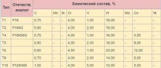
When working with metal, workers most often encounter situations where they need to cut a workpiece into pieces. It is difficult to do this procedure manually. The cut may be uneven, which will require additional effort to correct the problem. To perform the technological process as efficiently as possible, without much effort, you need to use a cutting machine.
Cutting machine
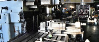
Machine design
Cutting equipment can be industrial or portable for private workshops and home production. It consists of several main elements:
- Frame made of metal corners, channels. It must be stable so that the cuts are smooth and the machine does not move when the engine is turned on.
- Desktop. It may have clamps for workpieces, a tape measure, and a protractor.
- Electric motor. Transmits rotational force to the cutting disc.
- The drive that supplies the working part of the machine to the workpiece.
The electric motor transmits force to the equipment using gears. There are two types:
- Belt - installed on industrial equipment. Allows you to work with the machine for a long time without interruptions. Produces minimal noise during operation.
- Toothed - installed on compact models of cutting machines. Takes up little space, which is suitable for small workshops.
The equipment is used for cutting various materials. To ensure safe working with it, manufacturers install protective covers on cutting discs, which open the working part shortly before contact with the workpiece.
The RVD cutting machine is special equipment that is used for cutting high-pressure hoses. These are elements of hydraulic and pneumatic systems. The devices are capable of quickly and safely making even cuts on workpieces. Additionally, they are equipped with systems that extract smoke from the working area.
Principle of operation
Gas cutting technique refers to the technology of gas flame processing of metals , in which the flame of a burning gas-air mixture heats the workpiece to a high temperature to perform cutting, surface hardening, surfacing or other technological operations.
The basic principle of gas cutting is the ability of metal to ignite in an environment of chemically pure oxygen. For the technical implementation of this complex physical and chemical process, a special metal cutter is used, which performs the following functions:
- mixing in a certain proportion of flammable gas (acetylene, propane, natural gas) with oxygen to form a heating gas-oxygen mixture;
- ignition of the heating mixture and heating it with a metal flame along the cut line;
- separate supply of a flow of heating mixture and a stream of oxygen to the cutting site.
The gas cutting operation, which is provided by the cutter with burning gas, consists of two technological stages:
- Preparation for cutting, which consists in heating the local zone of the workpiece to the ignition temperature of the metal. Heating is carried out by a flame torch of the burning heating mixture. At the site of the start of the cut, the metal is heated to white heat, which corresponds to heating to a temperature within 1100 degrees. C.
The local preheating mode is necessary so that the metal of the workpiece ignites in a stream of oxygen along the cut line without the use of an external ignition initiator.
- Direct gas cutting of a workpiece, which consists of burning the metal in a stream of oxygen supplied under pressure and blowing out the resulting combustion products in the form of hot particles from the working area. The cutting process proceeds in the following sequence:
- an oxygen stream under a pressure of 5-12 atm is supplied to the heated zone;
- upon contact with a heated surface, oxygen ignites;
- under the influence of an oxygen jet, the metal in the cut zone burns;
- combustion products - oxides - are blown out of the cutting zone in a stream, leaving behind a narrow groove.
Oxidation of the material of the cut workpiece occurs only in the area of action of the oxygen jet, so the penetration of oxides into the metal is excluded.
Technical specifications
Construction stores offer customers a wide range of cutting machines. Equipment has a number of technical characteristics that determine its price, efficiency, and productivity. These include:
- Electric motor power. This parameter affects what materials can be cut using the device and its efficiency.
- Engine rotation speed. The faster this parameter, the better the quality of the cut. The productivity of the machine directly depends on it.
- Settable cutting disc diameter. The possible thickness of the processed parts depends on the size of the equipment. The maximum diameter of the equipment is 400 mm.
- Dimensions of the machine. They influence how much space is required in the room and what size workpieces can be processed.
An additional parameter is the cutting angle. The functionality of the device and the initial location of the part on the desktop will depend on this. Machines for high pressure hoses are equipped with more powerful engines and additional mechanisms for holding parts during operation.
Cutting disc diameter
Typical design
The design of the cutter must ensure stable combustion of the metal in a stream of technical oxygen. The most common design of such a cutting unit is a two-pipe injection-type gas cutter (hereinafter referred to as IGR).
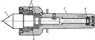
In Fig. Below is a diagram of a typical design of an acetylene IGR, consisting of two functional modules:
Barrel (not indicated on the diagram), represented by:
- a handle with two inputs for connecting hoses from an oxygen cylinder and an acetylene source - an acetylene cylinder or an acetylene generator;
- adjusting oxygen (item.
 and acetylene (item 7) valves.
The barrel is attached to the IGR body with a union nut.
A tip (not indicated on the diagram), consisting of the following elements:
- injector (item 6) and mixing chamber (item 5);
- tubes for supplying a combustible mixture (item 4) and an oxygen cutting jet (item 3);
- oxygen jet control valve (item 9);
- cutter heads with internal (item 1) and outer (item 2) mouthpieces.
Scheme of acetylene IGR.
In the design of the IGR, a special role is assigned to the injector (item 6 in the diagram), in which the process of continuous mixing of high-pressure oxygen and combustible gas flows (in this case, acetylene) occurs in order to create a gas mixture flow at the outlet of the mixing chamber (item 5). , having a speed lower than that of oxygen flow, but exceeding that of acetylene.
The created mixture is fed through a tube (item 4) into the nozzle and passes through the space between the outer and inner mouthpieces to ignite the heating flame. To regulate the injection process, the oxygen and acetylene supply channels are equipped with control valves (items 7 and 8).
A more complex design of gas cutting equipment is a three-pipe modification called an injection-free cutter . In non-injector models, there is no mixing chamber, and oxygen is supplied through two separate tubes to the cutter head, inside which oxygen is mixed with flammable gas. The absence of a mixing chamber provides a fairly good safety indicator, since there are no conditions for a kickback to occur.
Operating principle and varieties
Metal cutting machines are divided according to various factors. If we talk about functionality, there are two types of equipment:
- One cutting disc. Classic devices that have one electric motor. Suitable for workshops, repair work, and materials procurement. Low productivity does not allow the use of equipment for mass production.
- Two cutting discs. The equipment is considered more productive and allows for mass production. One motor with equipment is fixed in one place, the other motor with a disk is installed on a movable carriage, which makes it possible not to move the workpiece during operation.
Depending on the feed of the cutting part, there are three types of disc cutting machines:
- Pendulum feed. The usual option is to lower the working part from top to bottom. Can be done manually or automatically. Additionally, such machines are equipped with a mechanism for changing cutting angles to a horizontal position of the cutting disc.
- Front feeding of the cutting part. Modern equipment on which memory sensors are installed. Thanks to them, the master does not need to constantly change the cutting angles. This happens automatically.
- Bottom feed. The cutting disc is fed using an automatic system. You can set any angle, increasing the functionality of the machine.
Equipment selection
Before purchasing a machine, you need to familiarize yourself with the equipment selection criteria:
- Dimensions of the device. You need to choose depending on the availability of free space and the length of the products being processed.
- The engine power should be selected depending on the material being cut and its thickness.
- Possible cutting disc diameter. The size depends on the thickness of the workpieces being processed.
- Possibility of changing angles.
- Equipment control system.
Additionally, the machine can be equipped with lighting, protective shields, and clamps for parts.
Angle changes
Design and principle of operation of a machine for cutting sheet metal
The machine for cutting sheets or rolls consists of the following main parts:
- bed;
- feeding table with guides;
- longitudinal cutting block;
- guides;
- drive manual or electromechanical;
- bushings;
- Remote Control.
Depending on the production scale and purpose of metal cutting, the longitudinal and transverse cutting machine can be of the following types:
- manual;
- with electric drive;
- automated.
Some models for transverse and longitudinal cutting of rolled or sheet material are equipped with:
- handle;
- gear motor;
- electrical cabinet;
- length sensor (encoder);
- automatic control system;
- remote control for settings.
Making a cutting machine
If you wish, you can assemble a cutting machine with your own hands. To do this you need to prepare tools and materials. You will need metal corners, channels, bearings, an electric motor, automatic equipment start-up, a welding machine, a drill, and an angle grinder. Assembly steps:
- Making a homemade cutting machine begins with creating a drawing. It displays dimensions, moving elements, and electrical diagram.
- Next you need to make the frame. To do this you will need metal corners and channels. They are connected by a welding machine.
- The engine and moving elements are installed on top of the frame.
- An automatic equipment starter is connected, which is connected to the engine by wires.
The master needs to check the integrity of the homemade cutting machine and conduct a test run.
Rules for working with equipment
There are a number of rules that will help make metal processing safe:
- Check in advance for the presence of protective covers.
- Before starting the engine, check the integrity of the cutting disc.
- Securely secure the workpiece on the workbench.
- Wear safety glasses.
- Check the integrity of the wires.
- Check the clamping of the fasteners every week to prevent vibrations.
- Lubricate the bearings so that there are no problems when lowering the working part.
After each work process, it is necessary to clean the working surface and moving elements from chips formed when cutting workpieces. Change discs after chips appear on the cutting part or when they are worn down.
Cutting machine - equipment for cutting workpieces of various widths. To avoid an accident during operation, you need to choose the right equipment and check its fastenings on the engine.