27.03.2020
- Design
- Classification of turning cutters
- Types of turning tools for metal with the purpose of each
- Prefabricated
A lathe cutter is the main working tool that gives the workpiece (made of wood, steel or other material) the required size and shape. Both the accuracy of manufacturing the part and the very possibility of quickly and safely carrying out the required technological operations directly depend on its condition (degree of wear) and sharpness (quality of sharpening). The correct choice of tool also plays a role, so below we will dwell on both its dimensions and the varieties used today.
When operating equipment professionally, it is necessary to understand exactly what its main working tool is. Therefore, today we will take a comprehensive look at the cutter for a lathe, starting with its geometry, planes and angles, ending with the areas of use of certain variants of its design.
Design
Absolutely all options, from the most common to the very specific, consist of the following two key parts:
- a holder with a strictly defined cross-section, the shape of which is either rectangular or square, for reliable fixation in the equipment;
- a head with several usable planes and edges (each of which will be discussed below) - for direct processing of the material (be it alloy steel, cast iron or some other).
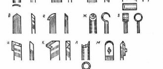
According to geometry, the following execution methods are distinguished:
- straight - both of its above-mentioned components are located either parallel or on the same axis;
- curved - with a slightly noticeable curvature of the profile inward;
- bent - with an obvious bend reaching an almost zigzag shape;
- retracted - the head is narrower in width than the holder and is placed either symmetrically along the axis or offset, to the right or left.
Also, absolutely all types of cutters for lathes that are relevant today can boast of a certain surface geometry, the relative arrangement of which we now move on to.
Planes
There are three:
- The main one is parallel to the reference and, accordingly, to the tool feed vector, which can be located both longitudinally and transversely.
- The cutting plane is perpendicular to the previous one, includes the main edge, and runs tangentially to the workpiece.
- Main secant – passes through the main edge, perpendicular in its role to the projection.
Add here an auxiliary one, which is a secant and is located at an angle of 90 degrees to the corresponding face.
It is important that the dimensions remain within the standard range, that is, do not exceed 160X100 - 630x1000 for rectangular tools and 40X40 - 400X40 for square ones.
Cutter angles
Their parameters depend on the type and conditions of use of the element we are considering, as well as on the hardness of its material and the characteristics of the workpieces being processed. The latter, in turn, determine the sharpness of the head, which means they can be:
- The main ones (according to the placement of planes):
- the front one specifies the degree of deformation upon impact, the efficiency of heat removal, and the applied force; should decrease with increasing hardness of the surface of the part;
- rear - affects the friction force, wear rate, and the quality of the final technological operation.
- Edges located between surfaces:
- sharpening – determines the strength of the equipment;
- cutting – determines the depth of penetration.
- main – sets the quantity and volume of chips to be removed;
- secondary - directly affects the degree of roughness, which decreases proportionally as it decreases.
Features of product geometry
The geometry of a shaped cutter depends on its design, which in turn depends on the size and profile of the part. The main ones are cutting angles, sharpening, the main front and back, and also for some products additional angles are introduced into the design. The parameters can be very different. Proper design of the tool shape and the correct selection of the grade of steel/steels for its manufacture will help to obtain a high-quality part from a workpiece. The calculation of the profile of a future product is carried out by specialists in 2 ways: analytical and graphical, each of which requires certain skills and the ability to use specific reference books and literature. Work experience is also important.
The quality of processing depends on the type of turning tools
The technological operation can be performed using either a roughing, semi- or finishing device. In the first case, due to the impressive mechanical-strength characteristics of the edges that do not overheat during the process, a relatively high speed of solving the problem is achieved (but accuracy may suffer, since the chips are removed in thick layers). In the second, as a rule, finishing is carried out - without unnecessary haste, carefully, to ensure low surface roughness, which is facilitated by a straight or shaped blade (not semicircular or through).
Hence the simple conclusion: you need to select a tool with an eye to the specifics of the goal to be solved.
Classification of turning tools
There are several features according to which the existing models are divided into groups. We invite you to take a closer look at exactly what features.
By manufacturing method:
- Monolithic (solid) - the head with the holder are made inextricably, from the same workpiece, from steel (usually alloyed).
- Prefabricated - a carbide plate is applied to their working part by soldering.
- Removable (adjustable) - similar to the previous ones, with the only difference that the reinforcement element is usually made of cermet and secured with bolts (screws, clamps), which means it can be dismantled and replaced.
In the direction of travel:
- right - in practice they are used much more often; to check, place the appropriate hand on the surface - the cutting edge of the tool should be located on the side where the thumb is looking at the part;
- left - used less often; if we compare them with their more popular counterparts, they are served in the opposite direction, which means that their blade, if you bring your palm up, will be on the other side.
Now let's return to the issue of dimensions and see, taking into account the specific features, what kind of cutters there are for a lathe in terms of their geometry.
According to the shape of the holder:
- square - sizes from 4 by 4 to 40 by 40 mm;
- rectangular - with an aspect ratio from 16 by 10 to 63 by 50 mm.
We discussed the structure of the head above, and we remind you that according to this parameter, instruments can be straight, curved, bent or drawn. There is another important point - the function that they will perform.
By type of destination:
- cutting - for molding blanks with straight edges (corners);
- pass-through – for ends, chamfering, external surfaces;
- groove - to create grooves of the required depth;
- boring – for processing holes, through and/or blind type;
- threaded – for making screw connections.
By the nature of the work performed:
- peeling (roughing) - layers of material are removed quickly, but without much care;
- semi- and finishing – for more thorough and accurate technological operations;
- thin – for quickly solving especially critical and even precision tasks.
By installation method:
If we consider how the type of turning cutters and their purpose depend on the characteristics of fixing the workpiece being processed, the classification will be carried out according to the location option:
- Radial - that is, at an angle of 90 degrees to the axis of the part; This is a classic option for most industrial enterprises, where it is important that the mounting and geometric positions of the tool are unified.
- Tangential - the edge is at an indirect angle; This type of installation is used relatively less frequently because fixation is more difficult, but it is relevant for non-standard cases that require maximum precision.
According to the material of the cutting part:
- Carbon metals with a hardening hardness of 60-64 or based on chrome-silicon, chrome-tungsten; are used relatively rarely, as they quickly overheat even at 240 or 300 degrees, and therefore already show poor results.
- Steel hardened to 62-65, categories R9K5F2, R9, R12; They are often used because they cannot be wiped and even at high rotation speeds they are able to retain their properties and withstand temperatures up to 650 0C.
- Metal ceramics - alloys based on tungsten-cobalt (VK8, VK6 - for cast iron) or titanium-tungsten-cobalt (T15K6 is especially popular); do not deform even at 900 degrees Celsius.
The markings deserve special attention: the designations of metal turning tools consist of 9 or 10 characters. Each number (or letter) regulates:
- 1st – installation option;
- 2nd – plate shape;
- 3rd – type of tool;
- 4th – back angle value;
- 5th – direction of movement;
- 6th – holder height;
- 7th – tail width;
- 8th – total length;
- 9th – edge size;
- 10th - is added optionally when necessary, and determines the key (for a given case) accuracy parameters.
Now, in order not to complicate the review, it’s time to move on to the most detailed consideration of the most frequently used options - so that you have a complete understanding of how, when and what they are used for.
PIPE CUTTING EQUIPMENT
In the production process of pipes, they have to be trimmed and cut, for which saws and cutting machines are used: Only sometimes scissors are used to cut off clogged heads.
Types of saws and cutters used for cutting pipes of various sizes
| Type of saws and machines | Pipe size, mm | |
| diameter | wall thickness | |
| Toothed circular saws Circular saws without teeth Hacksaw saws Circular saws with a pointed cutting edge Saws (machines) with an abrasive disc Pipe trimming machines, cutting Alligator shears | 38-102 20-102 5-38 12-102 1-89 38-150 20-50 | 3-8 2-8 0,5-2 2-4 0,1-5 ≥2 0,5-4 |
Pipe cutting machines
At the ends of the pipe, over 100-200 mm from the end, and sometimes more, there are significant irregularities that cannot be removed by trimming. Therefore, such ends of the pipes have to be cut off after rolling. In addition, the pipes are cut into measured lengths. For these operations, pipe cutting machines are used, which are currently the main equipment used for this purpose.
The most widely used are cutter pipe cutting machines; They are used for finishing cutting and trimming pipes to obtain smooth ends and ends with external or internal chamfer.
Cutting edgers are of two types by design: with a rotating pipe and with a stationary pipe. In machines of the first type, the pipe is clamped in the jaws of a rotating chuck, and the cutters are fixed in supports mounted on the machine bed. In machines of the second type, the pipe is clamped motionless, and the cutters are fixed in a rotating chuck.
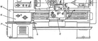
The figure shows a diagram of one of the pipe cutting machines used. This machine is designed for cutting pipe ends, removing external chamfers and internal burrs. The diameter of the cut pipes is 38–250 mm, the wall thickness is 4–12.5 mm.
Pipe cutting machine for pipes with a diameter of 38-250 mm
'The operating principle of the machine is based on the translational movement of the tool and the rotation of the pipe. The machine consists of the following main parts: bed 1,
gearbox
2,
spindle head
8,
cutting supports
4,
chamfering support 5, back stop
6,
hydraulic drive 7, electric motor
8,
cooling and lubrication systems.
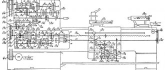
The figure shows a kinematic diagram of one of the pipe cutting machines.
Rotational movement of the spindle 5
transmitted from the electric motor / through V-belt transmission
2,
gearbox
3
and gear
4.
The pipe is clamped in the spindle with a collet clamp using a sleeve 6,
6
receives
translational movement to clamp the pipe 8
from the hydraulic cylinder. From the same hydraulic cylinder, the drive rollers 7, which feed the pipe into the spindle, are clamped or released.
The rotation of the lower drive roller is carried out by an electric motor 13
through V-belt drive
12,
bevel gears 11
and
spur gears 10.
Pipe cutting machine
The translational movement of the calipers with the cutters fixed in them is communicated by two hydraulic cylinders
14
acting on the racks
15,
to which the calipers with the cutters are directly attached.
To ensure synchronous operation of the calipers,
racks 15 16.
Operate the pipe cutting machine as follows; the pipe is fed along the roller conveyor and drive rollers 7 into the hollow spindle of the machine; clamp cylinder 9 is switched on;
the pipe is clamped by the spindle collets and begins to rotate with it; the cylinders for moving the calipers with cutters are turned on and cutting occurs; after the cut is completed, the calipers are quickly retracted to their original position, the pipe is unclenched and ejected from the spindle by a roller conveyor, and then dropped into the pocket.
For cutting thick-walled pipes with a diameter of up to 240 mm, machines of a slightly different design are used. In these machines, the pipe is clamped with one or two pneumatic chucks. The pipe can be clamped both during its stop and during its longitudinal movement. The cutters are fed automatically.
Pipe cutting machines with a fixed pipe are less common than those with a rotating pipe.
Edgers with emery wheel
The cutting tool of such a machine (figure) is an abrasive wheel driven through a V-belt drive 5 from an electric motor. 1.
Abrasive wheel 7 has a diameter of 300 mm and rotates at a speed of 900 rpm.
The spindle 8,
on which the abrasive disk 7 is fixed, is mounted on rolling bearings.
The spindle, electric motor and V-belt drive casing are mounted on a metal movable frame 3,
which is pivotally connected to a cast iron frame
4
6 is attached to the upper right end of the frame
for laying the cut pipe. The abrasive wheel is fed to the pipe manually.
Such machines are used for cutting pipes with small wall thickness after rolling them in KhPT or KhPTR mills, as well as in intermediate operations.
For final cutting of pipes, such machines are used very rarely, since the ends of the pipes after cutting are often uneven and have burns, which leads to the need for additional trimming on pipe trimming machines. Circular saws
Friction saws
Circular saws with a smooth, toothless blade (friction saws) are used for rough preliminary cutting and cutting of pipes, which are then usually re-cut or deburred. Friction saws are used for cutting thick-walled pipes in intermediate operations after drawing pipes on drawing mills, after rolling them on HPT mills, or trimming “frayed” ends after hot rolling mills.
The pipe is cut using a friction saw using a smooth round disc. When a smooth disk presses on the pipe being cut while it rotates at high speed, due to friction, a sufficient amount of heat is released to melt the metal of the pipe, causing the metal to melt and the pipe to be cut as a result. Since the cut occurs as a result of metal melting, large burrs form at the cut site.
The rotating saw blade is mounted on the shaft flange. A drive pulley is mounted on the other end of the shaft. In the middle of the shaft there is a neck, which is placed in a bearing mounted on the saw slide. A drive electric motor is mounted at the rear end of the slide. The slides are installed in special guides of the lower plate mounted on the foundation. The slide together with the saw can move in a horizontal plane in the direction of the cut. For installation on the shaft and for bolting the disk to the shaft flange, holes are drilled in the saw blade. The disk must be well straightened so that its cutting edge does not deviate to the side when rotating.
A notch is often made around the circumference of the disc, which increases the coefficient of friction. This helps speed up the process of cutting the pipe and at the same time the notch makes the edge of the saw blade wider than the blade itself. Cutting metal with a serrated blade creates a wider cut in the pipe body and reduces unnecessary friction between the side surfaces of the blade and the pipe.
To reduce the vibration of the disk and to ensure proper cutting of metal, its fastening to the shaft (shaft flange) must be strong enough. For this purpose, the disk is put on the shaft, then a washer is put on it according to the diameter of the flange. The inner side of the washer adjacent to the disk is bored out in such a way that along its periphery a small ring-shaped protrusion is obtained, with which the washer, when bolted, tightly presses the disk to the flange.
To ensure reliable holding of the shaft in a horizontal position and to prevent possible misalignment of the saw blade, the shaft bearing has a sufficiently long length.
The working shaft receives rotation from an electric motor through a V-belt drive. To obtain the required tension on the transmission belts, the electric motor is mounted on a guide slide with a special tension screw. The movement of the sled with the saw is carried out along guides installed on the plate using hydraulic or pneumatic cylinders.
For friction saws, discs with a diameter of 600-1800 mm or more with a thickness of 4-10 mm are used. As the edges wear, the discs are ground around the circumference, thus reducing their diameter. A reduction in diameter is allowed by 5-10%. It is not possible to allow a greater reduction due to the relatively large diameter of the flange, which, with a significant reduction in the diameter of the cutting disk, will interfere with cutting the pipe. The advantage of friction saws is that they cut at a high number of revolutions, and therefore at a high peripheral speed, so they have very high productivity.
The disadvantage is that when cutting the pipes they come out with melted ends and require additional mechanical processing. At the same time, during operation of the saw, friction creates a lot of noise and scatters molten metal in the form of sparks very far, which is unsafe for people working nearby. The noise generated by friction saws is significantly greater than that allowed by safety standards when working in production workshops. Therefore, recently, as much as possible, they try not to use friction saws.
Types of turning tools for metal with the purpose of each
For convenience, they are presented separately - with subgroups, areas of application, characteristic features, and current standard sizes.
Passing
An extensive category of tools, with the use of which cylindrical workpieces are ground precisely to a given diameter, and also steps of the required depth are made and chamfers are cut strictly at a certain angle. They themselves are divided into several subtypes.
Direct
Both parts, the holder with the head, lie completely along the same axis (or their relative position is parallel). Mainly used for removing layers of material from the upper (outer) surfaces of parts. They have the following standard sections and dimensions:
- square - 25 by 25 mm, needed for special operations;
- rectangular - 25 by 16 mm, applicable in general cases.
Bent back
They have a profile with a bend at the end (oriented to the left or right), which makes them quite convenient for thread processing of the ends of parts, as well as for removing various chamfers. In any embodiment, they must comply with the provisions of GOST 18877-73.
Based on the chosen area of equipment operation, they can be of the following sizes (in mm):
- 16 by 10 – for educational purposes;
- 20 by 12 – for non-standard cases;
- 25 by 16 – regular;
- 40 by 25 – for piece products produced to order and/or in small batches.
Thrust bent
This subcategory includes those types of metal lathe cutters in which the bend, despite its obvious curvature, is not a key design feature. The main point is the possibility of removal along the entire axis of rotation of the part, which allows you to remove the maximum amount of excess material in literally one pass. Due to this, such tools are now most in demand when turning cylindrical workpieces. Their overall grid, in millimeters, looks like this:
- 16 by 10;
- 20 by 12;
- 25 by 16;
- 32 by 20;
- 40 to 25.
Scoring
Similar to walk-through ones, but with a triangular plate. Thanks to this feature, future products are processed perpendicular to the vector of their rotation, which in some cases is simply necessary. Their standard sizes are standard and include only 3 options: 16 by 10, 25 by 16 and 32 by 20 mm.
Cut-off
The most common types of cutters for a metal lathe in modern practice, used for quickly producing a large batch of parts with right angles (edges, planes). They are distinguished by a thin leg and the presence of a soldered plate of increased hardness; they can be either left- or right-oriented in the direction of their movement. Also relevant when creating grooves of the required depth on a smooth surface. They have holders of the following dimensions:
- 16 by 10 – for educational equipment;
- 20 by 16 or, less often, 20 by 12 - for general cases;
- 40 by 25 - again, for piece products ordered separately.
Threaded
Another fairly broad group, divided into two categories - according to the nature of the plane being processed.
For external thread
They are made of durable alloys (hardened steel, cermets), spear-shaped, allowing you to apply metric and other helical spiral lines of the required depth. Available in the three most common sizes: 25 by 16, 16 by 10 and 32 by 20 mm (the latter are relatively rare in use).
For internal thread
Relevant only for those parts that have technological holes of large cross-section. The main design feature is the presence of a serpentine head. The holders boast a significant length, necessary for the tool to penetrate deeply and carefully into the fixed workpiece during the operation. Suitable only for equipment that is equipped with a “guitar”. Their dimensions, in millimeters:
- 16 x 16 x 150;
- 20 x 20 x 200;
- 25 x 25 x 300.
Boring
We continue to consider the turning cutters used in today's conditions: the types and purpose of options in this category vary depending on the specifics of the area being processed. There are two fundamentally different subgroups.
For blind holes
With a triangular head, slightly curved to the right or left (for better penetration). In appearance they could be similar to scoring ones, if not for their dimensions, in particular, the elongated holder, which, ultimately, determines the maximum possible diameter for boring. Its three most popular models have the following geometry (in mm):
- 16 by 16 by 170;
- 25 by 25 by 300;
- 20 by 20 by 200.
For through holes
Used after drilling operations. A layer of material approximately equal to the bend of the main part of the tool is removed. The head is of a specific shape, with a slight curvature, must comply with the requirements of GOST 18882-73, which also regulates the dimensions - similar to those of the product from the previous subcategory.
Tips for choosing a shaped cutter
As stated earlier, the tool is made for a specific part. Manufacturing work begins with design. The design stages are as follows:
- determined by the type of tool, the profile of which directly depends on the drawing data of the part;
- determined with the main and connecting dimensions, as well as with the angles of the cutting part and the installation of the cutter;
- perform a calculation of profile dimensions, the so-called correction calculation;
- are determined with tolerances.
Based on this, the material and manufacturing method are selected, and a drawing of the future product is made. In addition, they are determined with a holder for mounting on a specific model of machine. If necessary, it is also made. In most cases, a template is initially made, and a counter-template is used to control the dimensions during operation of the product.
Conclusion: a product is manufactured according to a known profile of a part that will be sharpened using a tool. The profile is determined in the plane of the front face and in the one that is perpendicular to the rear surface.
Prefabricated
The types and purposes of metal turning tools of the so-called universal type deserve special consideration. Their design provides a clamp, either a bolt or a screw, or even a more specific clamp, which allows you to install a wide variety of plates, changing them as needed. In this way, you can process parts at all desired angles, controlling the speed of the technological operation, the accuracy of metal removal and other parameters. These tools find their application in CNC production complexes, the program control of which is written for contour precision turning and solving other, equally non-standard tasks.
Holders and their sizes
We have looked at what types of cutters there are for a lathe, now let’s return to the part with which they are fixed in the equipment. During the review process, we have already repeatedly mentioned the most popular dimensions, now let's list them in full - from smallest to largest. For clarity and ease of perception - in the form of the following table:
| section | size, mm | |||||||||
| square | 4 x 4 | 6 x 6 | 8 x 8 | 10 x 10 | 12 x 12 | 16 x 16 | 20 x 20 | 25 x 25 | 32 x 32 | 40 x 40 |
| rectangle | 16 x 10 | 20 x 12 | 25 x 16 | 25 x 20 | 50 x 52 | 40 x 32 | 50 x 32 | 50 x 40 | 63 x 50 | — |
It is also necessary to take into account the variety of lengths needed in specific cases, for example, for boring holes. This parameter usually varies from 150 to 300 mm. We have tried to cover in as much detail as possible the issues of the variety of metal turning tools, markings and purposes of their various options, so that you understand which one to choose for the required technological operation. Well, you can find equipment that is compatible with most of these tools at the Izhevsk plant.
Selecting cutting mode
Cutting modes are selected depending on the following factors:
- brands of processed material;
- brand of material from which the cutting tool is made;
- length of the workpiece and its diameter;
- method of installing the tool on the machine;
- profile configurations and depths.
Approximate cutting modes with shaped cutters on metal-cutting machines, depending on the diameter of the workpiece and the width of the cutter, are shown in the table.
| Workpiece diameter, mm | Cutter width, mm | Feed speed, mm/rev. |
| 20 | 8 | 0,03 ÷ 0,09 |
| 10 | 0,03 ÷ 0,07 | |
| 15 | 0,02 ÷ 0,05 | |
| 25 | 8 | 0,04 ÷ 0,09 |
| 10 | 0,03 ÷ 0,085 | |
| 15 | 0,035 ÷ 0,75 | |
| 20 | 0,03 ÷ 0,06 | |
| 40 | 8 | 0,04 ÷ 0,09 |
| 10 | 0,04 ÷ 0,085 | |
| 15 | 0,04 ÷ 0,08 | |
| 20 | 0,04 ÷ 0,08 | |
| 30 | 0,035 ÷ 0,07 | |
| 40 | 0,03 ÷ 0,06 | |
| 60 | 8 | 0,04 ÷ 0,09 |
| 10 | 0,04 ÷ 0,085 | |
| 15 | 0,04 ÷ 0,08 | |
| 20 | 0,04 ÷ 0,08 | |
| 30 | 0,035 ÷ 0,07 | |
| 40 | 0,03 ÷ 0,06 | |
| 50 | 0,025 ÷ 0,055 |
In the video you can watch the process of turning a ball with a shaped cutting tool:
We ask you to share your experience of turning workpieces with a shaped cutter in the comments to the text, and for those who designed - the nuances of making a drawing of the cutter itself, holder, template and counter-template.