After being compressed by a compressor, the air stream often contains impurities, moisture and oil. Their penetration into the system is unacceptable, therefore, before entering the pneumatic tool or other device, a moisture-oil separator for the compressor must be installed. To buy the required part, you need to understand the existing types and know the parameters that you should focus on when choosing. But you can assemble the moisture separator yourself if you have an assembly diagram, a detailed description of the process and the necessary components. More on all this in the material below.
Water-oil separator - definition and purpose
In order for a pneumatic tool to work efficiently and remain in good condition for a long time, the air supplied to it must be clean. The air filter located at the entrance to the device protects from dust and other mechanical contaminants. But it is also important to prevent oil and moisture from getting inside the device.
Important! Moisture is contained in the air that enters the compressor from the atmosphere, and its content can be very significant. In addition to it, oil enters the air flow, which is used to lubricate the parts of an air piston or other type of oil compressor.
When moisture and oil get inside the pneumatic tool and mix, they can cause significant damage to the device and also reduce its operating efficiency. To clean the air flow from these impurities, you need a special device. For this purpose, a moisture-oil separator has been created and used.
Cyclone oil separators (oil separators)
To get rid of the shortcomings of synthetic fiber filter fabric, cyclonic oil separators .
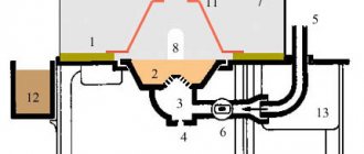
Rice. Operating principle of the engine crankcase ventilation system with a cyclone oil separator: 1 – cyclone oil separator; 2 – pressure regulation valve; 3 – charge air cooler; 4 – turbocharger; 5 – gases breaking through the piston rings
Crankcase gases are supplied through a channel inside the engine into a cyclone oil separator. The cyclone oil separator causes the air to rotate. Due to the resulting centrifugal force, the oil mist hits the wall of the oil separator. Drops of oil form there, which flow through a channel in the crankcase into the oil pan. The air, cleared of oil mist, is supplied to the air intake duct through the pressure control valve.
The cyclone oil separator is equipped with a special valve that limits the vacuum in the engine crankcase, since a strong vacuum can damage the engine oil seals and other rubber seals.
Rice. Diagram of operation of the cyclone oil separator pressure control valve: 1 – crankcase gas supply pipeline; 2 – air intake pipeline; 3 – membrane; 4 – compression spring; a – open position of the valve; b – valve closed position
The pressure control valve is located in the cover of the cyclone oil separator. It consists of a diaphragm and a compression spring and regulates the pressure when air is removed from the crankcase. The pressure control valve closes when there is a strong vacuum in the intake channel. When there is a slight vacuum in the intake channel, it opens by the force of a compression spring.
We recommend: How to replace the air filter on a Ford Fusion?
Design features and principle of operation
The task of the dehumidifier is to reduce the level of air humidity to optimal limits . Depending on the type of this structure, its operating principle changes:
- using centrifugal forces - vortex cleaning systems;
- using substances that absorb liquid - adsorption systems.
The classic vortex type water separator operates on the principle of a cyclone. The air flow enters the device and, rotating around the central axis, is thrown towards the walls of the container. In this case, moisture condenses on the surface and flows to the bottom, from where it is removed through the outlet, and the air flow goes outside.
According to the drawings, the design of this type of dryer is as follows. Entering the housing, the air flow is directed to the impeller and spins. Moisture particles are thrown towards the walls of the glass, settle on them and fall down into the area with contaminants separated by the damper. The air moves into the deflector through an additional air filter that retains the smallest solid particles, and is then discharged outside. Moisture is removed through a hole in the bottom of the glass.
Adsorption dehumidifiers contain in their design a substance that absorbs liquid. The air flow passes through such a filler and the dried air is discharged outside. Periodically used granules need to be replaced with new ones.
Kinds
According to the method of separating a liquid substance from the air flow, modern cleaning systems are vortex, adsorption and modular.
Vortex cleaning systems
Designs of this type are in high demand - they are easy to use and maintain, have a low price with high efficiency, but only hold large drops of liquid. Therefore, vortex moisture separators are used as preliminary rough cleaning of the passing air flow. Such devices are used in industrial workshops, as well as for home tasks.
Adsorption cleaning systems
Devices of this type remove liquids from compressed air using actively absorbing substances, such as silica gel, calcium chloride and others. Their operating principle: humidified air passes through granules with a desiccant substance and purified air is supplied to the connected instrument. Such devices are used in scuba filters, imported heavy trucks, etc.
Modular cleaning systems
Modular air dryers most effectively protect pneumatic equipment from water, oil particles and dust. They include several sequentially arranged blocks: a cyclone separator, a fine filter, and a carbon filter . The latter ensures almost ideal purity of the exhaust air directed to tools for which carbon filtration is not provided.
Design - oil separator
| Scheme of recirculation flows in a cyclone according to Fontaine. |
Crankcase ventilation valve
The design of the oil separator, which creates favorable conditions for effective separation, is shown in Fig. 1 g. Its main advantages compared to those given above are the correct input and organization of the movement of the gas flow (reducing the speed at the lower edge of the outlet pipe), a successful solution for the removal of deposited liquid flowing in the form of a film along a wall sufficiently distant from the outlet pipe, which reduces the possibility of its breakdown and removal from the separator.
| Oil collection diagram. |
The design of the oil separator is simple, but only its correctly selected dimensions and design ensure successful oil separation.
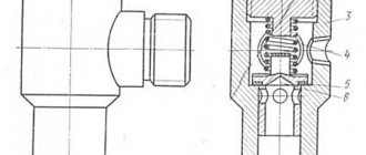
One of the oil separator designs is shown in Fig. IX. With a sharp turn of ammonia vapor entering through pipe 2 and discharged through pipe 3, oil particles, by inertia, are deposited at the bottom of the oil separator housing, from where they are transferred back to the compressor.
| Dependence of changes in power consumption or changes in refrigeration capacity of a 5ВХ - 350 / 5FS screw compressor unit when adjusting spools and pistons. |
Oil carryover depends on the design of the oil separator, the mass velocity of the steam-oil mixture in it and the properties of the oil.
The design of the liquid separator is in many ways similar to the design of the oil separator. As in oil separators, the separation of liquid refrigerant droplets is based on a sharp change in the speed and direction of movement of the refrigerant vapor, during which the ammonia droplets separate and accumulate at the bottom of the apparatus.
Since purely mechanical methods are insufficient for effective oil separation at high steam temperatures, other physical methods are also used in the design of oil separators. In addition to this, the steam of the working fluid is forced to repeatedly change the direction of movement and come into contact with a developed surface to deposit oil, for example, in a nozzle 6 made of metal rings with a diameter of 8 - 10 mm. Cold water should not be supplied to the coil, as condensation of the working fluid on its surface is possible. To reduce this phenomenon, it is advisable to direct the water already used in the condenser to the oil separator coil, branching part of it at the exit from the condenser.
Inertial separation of oil and moisture is carried out in three ways: loop-shaped rotation of the air flow, reflection of the air flow from the wall and rotational movement of the air flow. In the designs of oil separators, these methods are used separately and in different combinations.
Cleaning of oil-contaminated exhaust steam is carried out by passing it through oil separating devices of various designs. Common to all designs of mechanical oil separators is the use of their developed surface to deposit oil droplets coming along with steam. To increase the steam deoiling effect, mechanical oil separators are supplemented with steam flushing devices.
The most promising is the oil separator proposed by V. A. Frolov, which includes a nozzle for aggregating oil particles before decanting. This proposal was used in the design of the oil separator at the Ust-La - Binsk plant.
| Ammonia inertial oil separator type M. |
In oil separators of the second type, inertial separation of oil droplets occurs, the density of which significantly exceeds the density of the refrigerant vapor. Oil separation occurs as a result of a sharp change in the speed and direction of steam flow or under the influence of centrifugal force. Some oil separator designs combine different methods of oil separation.
Criterias of choice
When choosing a moisture-oil separator, it is necessary to take into account the equipment for which it is purchased - for Kamaz, MAZ or other brands of trucks, painting equipment, sandblasters, etc.
Important! Depending on the tool used, the type of oil and water separator, the diameter of the inlet connection (1/8, 3/4, 3/8, etc.), operating pressure, the presence of additional filters, and other parameters are selected.
For example, for air guns used in painting, there is no need to buy a filter that passes a large amount of liquid within a minute. It is recommended to consider devices with fine filters. Whereas for production needs a high degree of purification is not required, but there is a need for high throughput.
TOP 3
You can purchase a good and reliable moisture-oil separator both in a specialized store and on Internet resources, for example, on Aliexpress. The TOP below presents the best models collected from customer reviews and expert reviews.
Wester 816-002
This is a device for purifying air from impurities, oil and water, as well as for adjusting pressure and maintaining the selected level. The kit includes: a moisture-oil separator, a gearbox with a pressure gauge and a lubricator. The internal diameter of the inlet and outlet holes is 1/4, the working pressure is 10 atmospheres. The device is intended for spray guns or other pneumatic tools.
Wester 816-002 on Yandex Market
Air preparation unit 1/2 4500 l/min
This compressed air preparation unit includes a moisture-oil separator, a pressure regulator and a lubricator. The device allows you to clean, dry, lubricate the air and adjust its pressure before feeding it into the pneumatic tool after the compressor. Its characteristics:
- aluminum body, weight – 980 g;
- internal thread of the hole for air inlet and outlet – ½;
- throughput – up to 4500 liters of liquid per minute;
- operating temperature range - from five to sixty degrees;
- liquid drainage is automatic due to the installed valve;
- Oil supply intensity is adjustable;
- body volume – 40 ml;
- lubricator body volume – 75 ml.
Air preparation unit 1/2 4500 l/min on Yandex Market
Licota PAP-C207B
This is a three-level fine oil separator filter with a 3/8 internal thread. The device has three different filters, the degree of purification of which is 5, 0.3 and 0.01 microns, due to which the air flow is cleared of liquids by 99.9%. Its advantages:
- an indicator scale is installed in the central module, which turns red when it is necessary to replace the filter element;
- the granules included in the third module are painted pink if they need to be replaced;
- condensate is drained automatically due to a special valve;
- the design comes complete with a pressure regulator and pressure gauge;
- the device is capable of passing up to three thousand liters of water per minute, its capacity is 80 cm2;
- the maximum permissible pressure is 17.5 kg per cm2.
Licota PAP-C207B on Yandex Market
Oil separator
Air Conditioning Compressor Bearing Replacement
The oil separator comes with an oil drain valve.
Oil separators, oil collectors, dirt traps, liquid separators, heat exchangers of freon units, air separators, brine concentrators and other auxiliary devices are mounted on walls, columns, ceilings and other structural elements of buildings.
Oil separator 7 is a supporting structure. There is an oil sump at the bottom of the oil separator.
Oil separator 1 is a supporting structure.
Oil separators are installed between the compressor and the condenser. They serve to separate oil carried away by agent vapors from the compressor. This reduces the flow of oil into the evaporator and condenser and improves the performance of the latter. Oil separation in the oil separator occurs mainly due to a change in the direction and decrease in the speed of steam movement. Cooling the vapors in the oil separator also contributes to a more complete separation of the oil.
Oil separators are installed in front of the condenser and serve to catch oil carried away from the compressor into the discharge line. The separation of oil from steam occurs when there is a sharp change in the speed and direction of the flow. Sometimes a nozzle made of Raschig rings or metal shavings is placed in oil separators, to the surface of which the oil carried away by the agent adheres.
We select the oil separator according to the diameter of the compressor discharge pipe and check the vapor velocity in the device.
Oil separators. For most modern refrigeration machines, oil separators are supplied with the compressor and are mounted on a common frame. In existing, previously installed installations, bubble separators are used, which are filled with ammonia. Ammonia vapor passes into the condenser through a layer of liquid ammonia.
Oil separators using these purely mechanical methods of oil separation capture between 40 and 65% of the oil entrained in the steam. The rest of the oil is carried away with the working fluid into heat exchangers.
An oil separator with gas washing and its connection diagram are shown in Fig. Oil separators of this type are installed so that the outlet of the pipe /, through which steam is supplied to the oil separator, is 125 - 150 mm below the liquid level in the vessel. Since the oil separator and the condenser are connected by steam and liquid pipes, they turn out to be like communicating vessels.
| Maximum spans between pipeline fastenings in m. |
Oil separators and oil collectors are mounted on brackets embedded in the walls or on concrete pedestals to which they are bolted. Liquid separators are installed on brackets with a rubber gasket about 10 mm thick, under the support legs. Linear and drainage receivers are installed on concrete pedestals. The correct installation of auxiliary equipment is checked by a plumb line in two planes, and receivers - by level. The control station of a large installation is mounted with preliminary marking of the axial lines for the collectors, which are secured to the frame with clamps. Then, shut-off and control valves are installed and holes are marked on the panel panel for the passage of extended spindles.
Oil separator with wet and dry chambers.
Oil separators are made of reinforced concrete, brick or rubble stone.
Oil separators using these purely mechanical methods of oil separation capture between 40 and 65% of the oil entrained in the steam. The rest of the oil is carried away with the working fluid into heat exchangers.
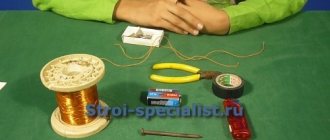
Making a moisture-oil separator with your own hands
The simplest vortex or adsorption moisture-oil separator can be made from various available materials. All you need is free time, as well as knowledge of the assembly diagram of the desired structure.
Vortex (cyclone) filter
oil and moisture separator is easily assembled from a fire extinguisher, a liquefied gas cylinder or from a pipe of any length . The diagram for assembling the device from a piece of metal pipe is as follows.
- You need to make a hole in the base of the housing and, by welding, attach a tap to it to drain the accumulated liquid.
- A fitting for the outlet of the air stream should also be attached to the top of the pipe by welding.
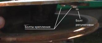
- Then you need to step back at least 15 cm from the bottom and drill a hole in which, using welding, secure a fitting for the entrance of the air stream so that it enters tangentially. This will allow the formation of a vortex flow necessary for cleaning from contaminants.
- To install the structure, legs with bases should be welded to it for stability.
- If necessary, the device can be painted.
On a note! For effective air purification and preparation, the structure is installed vertically.
Adsorption filter
A high-quality homemade adsorption moisture separator is made from a water filter and silica gel litter for pet litter. A short metal tube is also needed. The procedure for manufacturing the structure is as follows.
- Measure and cut the tube to such a length that when installed in the lid it touches the bottom of the filter. Drill a number of holes in it to allow the air flow pumped by the compressor to exit.
- Install a plug at the bottom of the tube to prevent filler from getting inside.
- Insert the upper part of the tube into the filter cover and seal the joints with a glue gun.
- Attach a mesh to the top of the lid or tube to prevent filler from penetrating into the air duct.
- Place silica gel in a flask, install a tube with a lid in the filter and screw it securely.
- Attach the compressor hose to the inlet fitting of the assembled device, and to the outlet - a hose for a pneumatic tool, for example, a spray gun.
Another substance used to fill the filter is silicate gel, which not only effectively absorbs liquid, but is also regenerated . To restore its properties, it is enough to place such a filler in the oven for a period of two to three hours.
Advice! It is recommended to purchase a gel with a color indicator. If it changes color, it means it needs to be replaced or dried.
Separation of oil from exhaust gases
Oil separation devices are used not only on air or other gas compressors. Exhaust gas purifiers are popular among car owners.
Often such devices are made by hand from scrap materials. It turns out to be a completely effective system for cleaning crankcase gases for a car.
How to make a crankcase oil separator
The simplest device, functionally “tailored” for separation for cars, can be made from plastic plumbing supplies.
A simple design made by the car owner himself from a set of plumbing accessories. Inexpensive and quite effective for used cars
The set of parts, the so-called crankcase oil separator, is indicated by a modest list:
- Plumbing coupling (1 piece).
- Brass fittings (2 pcs.).
- Plumbing plugs for the coupling (2 pcs.).
- Automotive fuel hose (1 pc.).
- Metal mesh for washing dishes.
Installation Requirements
When installing dehumidifiers, you need to follow a few simple rules to achieve maximum efficiency of this device.
- Equipment must be installed in such a way as to ensure that the coldest air possible enters the system. This will reduce its humidity level.
- The design should be checked periodically to ensure that air is moving through the dryer at maximum pressure.
- It is necessary to regularly carry out maintenance of the moisture separator, promptly remove accumulated liquid, change the filler, dirty filters, and failed elements.
- For welding and sealing joints, you need to use only high-quality materials.
- Before installation, fittings and tubes should be checked to ensure that there are no obstacles to the passage of air.
- The device must be installed strictly vertically and securely fixed.
- When installing, you need to make sure that the air will move in the right direction. The advantage of factory devices is that they usually indicate with arrows which direction the air flow will move.
So, a moisture-oil separator is a device installed in front of a pneumatic tool to clean the compressed air stream coming from the compressor from moisture, oil and foreign solids. You can make such a device yourself or purchase it in specialized stores. It is recommended to choose the second option, since homemade devices are less effective and functional.