Development board in electronic circuits
It is rare that a real Arduino project contains less than 5-10 circuit elements connected to each other. Even in a simple, well-known beacon circuit, 2 elements are used, an LED and a resistor, which must somehow be connected to each other. And this is where the question arises of how to do this.
Solderless breadboard
At the moment, there are the following main installation methods that are used in electronics and robotics at the prototyping stage:
- Soldering. To do this, use special boards with holes into which parts are inserted and connected to each other by soldering (using a soldering iron) and jumpers.
- Twist. In this technology, the contact connections of the devices are combined with the breadboard by winding a clean wire to the pin contact.
- Board for installation without soldering. The English version of the name of a solderless breadboard is breadboard.
- You can also hold the contacts with your hands or teeth, glue them with a glue gun, or fasten them with electrical tape or tape. In this article we do not consider such exotic options.
Solderless Breadboard
The most modern option for prototyping is the solderless breadboard, which has undeniable advantages:
- The ability to carry out debugging work a large number of times, changing the modification of circuits and methods of connecting devices;
- The ability to connect several boards into one large one, which allows you to work with more complex and large projects;
- Simplicity and speed of prototyping;
- Durability and reliability.
Development board
Of course, this mounting option also has disadvantages:
- In real projects, the connections on the board will not be as reliable as with soldering. Any vibration will slowly weaken the contacts and this will certainly lead to unexpected problems over time. Therefore, in real projects other types of installation of elements are used.
- The appearance of projects with noodles in the form of wires over the endless white spaces of the board cannot be called professional and aesthetic. They want this kind of look that always fascinates viewers and gives the project the image of something “terribly complicated, since there are so many wires.”
- A board with this type of installation will always take up more space due to overhanging wires. This means that it requires a large volume housing with fixation and vibration protection.
- Breadboard cost. Even though the boards are not expensive devices, you will still need to purchase them in addition to the microcontroller and other elements. Fortunately, there are a large number of inexpensive options and ready-made kits with circuit boards included on the market today. Some options can be found in the next section of our article.
Despite some disadvantages, beginners have practically no alternative options for simplicity and accessibility for installing their first circuits. Today you can find a huge number of projects in which all the elements are placed on the breadboard. Almost all examples from textbooks on the basics of robotics and Arduino use this mounting option. Therefore, we recommend that you take a closer look at this structural element.
Short circuit.
The main thing when assembling circuits on a breadboard is not to create a short circuit. What is a short circuit? This is when we connect the contacts of a circuit in a way that is not intended and a very large current flows through the circuit. We must always be careful to assemble the circuits on the breadboard in such a way that there is no short circuit.
In our instructions for working with a breadboard, we have prepared several diagrams for you. Let's practice and try to determine where the short circuit is.
Rice. 8. Is there a short circuit here?
Rice. 9. Find the short circuit.
Rice. 10. Is there a short circuit or not?
Buy a development board
We have traditionally made a selection of the most popular boards that can be bought in online stores and provided links to the most reliable suppliers on Aliexpress.
| 3 in one kit: MB102 development board with 3.3V/5V power supply and 65 wire sets | Development board MB102 Breadboard 830 pins | Set of 6 Mini Breadboards 170 Pins Mini Breadboard kit for Arduino |
| Development board 4 in one - 700 connectors from the famous WAVGAT brand | Standard development board 8.5CM x 5.5CM 400 headers | Starter Kit – a set of a breadboard, Arduino and wires |
Preparation and shielding
In order to work with a breadboard, especially if it is intended for solderless mounting, you first need to do some preparatory work. This is especially true if the board has not been used for a long time.
Preparation includes cleaning the breadboard from dust. You can use a soft brush to do this, and you can use a vacuum cleaner or a can of compressed air to clean the holes.
The next step is to test the conductive paths with a multimeter to avoid wasting time searching for a possible loss of contact when installing the circuit.
When debugging devices, they may not work correctly due to various interferences and induced currents that arise during the operation of the circuit. To eliminate this phenomenon, it is necessary to use shielding of the breadboard.
To do this, use a metal plate attached to the bottom and connected by soldering to a common bus, which will subsequently become negative.
To successfully use a breadboard for soldering and carry out quick debugging, it is advisable to purchase several breadboards of different sizes.
Firstly, this will allow you to assemble complex circuits in separate blocks, debugging each one, and later connect them into one device. Secondly, this way you can assemble additional devices that may be needed to control the operation of the main circuit.
It is better to purchase a development board with a set of connecting wires. They are also called “jumpers”.
But in some cases, you can save a significant amount if you buy a board for solderless mounting that is not equipped with connectors. In this case, you can make them yourself from a suitable wire.
The ideal cable is KSVV 4-0.5, used in the installation of fire alarm systems. This cable has 4 insulated cores of thin copper wire with a diameter of 0.5 mm. One meter of cable will be enough to get many connecting jumpers.
During installation, you must always reliably connect all terminals of semiconductors and microcircuits. Even if any pins are not used, they must be connected to a common bus to avoid induced currents.
When using development boards, you can only use low-current parts that operate on a voltage of no more than 12 V. It is prohibited to connect 220 V alternating current from a household power supply to the breadboard.
Proper use of a breadboard for solderless mounting will significantly simplify the assembly of the entire circuit and reduce the cost of manufacturing the device in which such a circuit will be used.
Development board diagram
To know how to use a development board, you need to understand the principle of its design. It's quite simple.
Development board diagram
The development board has a plastic base with many holes (the standard distance between them is 2.54 mm). Inside the structure are rows of metal plates. Each plate has clips that are hidden in the plastic part of the unit.
The wires are inserted into these clips. When a conductor is connected to one of the individual holes, the contact is simultaneously connected to all other contacts of the separate row. Therefore, by connecting the contacts of other devices to the remaining clips, we connect them with a conductor - a rail with clips.
It is worth noting that one rail contains 5 clips. This is a common standard for all development boards. That is, up to five elements can be connected to each rail, and they will be interconnected.
It should be noted that although there are ten holes in each row, they are still divided into two isolated parts, five in each. Between them there is a rail without pins. This design is necessary to isolate the plates from each other, and allows you to simply connect chips made in DIP packages.
Connecting the chip to the breadboard
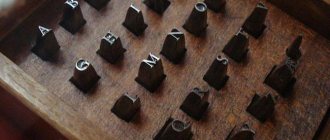
To make it easier to navigate, the breadboard also contains numerical and alphabetic symbols that can be used as a guide when creating, for example, wiring instructions.
Some development boards also include two power lines on each side. Typically, the “red line” is used to supply “+” voltage, the “blue” line for “-”. Due to the presence of two power rails, two different voltage levels can be supplied to the board.
Attention! It is absolutely unacceptable to use breadboards with a voltage of 220V!
If the board is large, then the power lines “break” in the middle. This allows for more connection options. For example, you can assemble devices with 3 and 5 Volt power on one board.
Power bus
For this task we will need additional jumper wires. These are wires with a pin at both ends.
Let's use the top two horizontal lines to supply power to three LEDs at once.
On a note. It is customary for the red line to indicate the positive contact of the battery, and the blue line to indicate the negative contact.
Insert the button into the gap in the negative power line.
We press the button - all three LEDs light up simultaneously.
Main types of development boards for Arduino
Development boards differ in the number of pins located on the panel, the number of buses and configuration. There are boards in which contact connections are made by soldering, but working with them is more difficult than with solderless devices and we will look at them in another article.
Large development board
Colored breadboards
Breadboard with markings
Depending on the characteristics, the most common types are:
- For assembling large chips, solderless boards with 830 or 400 holes are mainly used. For connecting several components and supplying wires to the necessary points - 8, 10, 16 holes;
- With the presence of grooves for adhesion of boards, which allow the implementation of fairly large projects;
- With self-adhesive on the base for secure fastening to the device;
- With symbols printed on the board for connecting devices.
Depending on the cost and manufacturer, the package may also include additional accessories - jumper wires, various connectors. But the main quality criterion always remains the number of contact connectors and their technical characteristics.
Purpose and device
The development board for solderless assembly allows you to mount an electrical circuit and run it without using a soldering iron. In this case, you can check all the parameters and characteristics of the future device by connecting measuring and control devices to the board.
A breadboard is a plate made of a polymer material that is a dielectric. Mounting holes are drilled on the plate in a certain order, into which the leads of the parts - components of the future device - should be inserted.
The holes allow the connection of leads with a diameter of 0.4-0.7 mm. They are located on the board, as a rule, with a pitch of 2.54 mm.
To simulate the connections of the component leads to each other, the breadboard has special conductive plates that connect the holes in a certain order.
Typically, these connections are made in groups along the board along its long sides. There may be two or three such rows. These contact groups are used as buses for connecting power.
Between the longitudinal rows, the holes are connected by plates in groups of five. These plates are located in a direction across the board.
How to use a development board
Using the breadboard is quite simple. When creating a circuit, the necessary elements are inserted into the holes on the plastic case - capacitors, resistors, various indicators, LEDs, etc. The width of the connectors allows you to connect conductors with a cross-section from 0.4 to 0.7 mm to the contacts.
Connection diagram of the LED to the circuit board
For example, you need to connect two elements together - an LED and a resistor. To do this, you take the leg of the first element (LED) and insert it, for example, into row number 2. You insert the second leg into another row. For example, 3. If you insert a leg in the same row, the circuit will not work, because both legs will be connected through a common rail by an iron conductor. There will be a short circuit. The current will flow through the connection directly, bypassing the LED. There will be no benefit from this.
Connecting an LED to a breadboard. We place the LED in a convenient place. The main thing is that for each leg there is its own row
If you insert a contact into an adjacent row, there will be no short circuit between them, because adjacent rows are not interconnected by conductors (after all, only 5 contacts in one row are connected). It doesn’t matter which row you stick the leg into. The main thing is that it is not the same as the first leg.
For convenience, in real schemes the second leg is placed not in the adjacent row, but in any other, a little further from the first. You need to choose the installation location taking into account the size of the LED itself, so as not to bend the contacts too much.
So, we have secured the LED - it stands steadily with both legs in rows 2 and 3. Let's now connect a resistor to this circuit. We will take one resistor leg and insert it in the same row as one of the LED legs. For example, in row number 3 - anywhere. There are 5 contacts in one row, it doesn’t matter which contact we end up in, the main thing is that it’s in the same row! Then we insert the second leg of the resistor into another row, for example, into the seventh.
Connecting an LED and resistor to a breadboard. We connect one legs of the elements
It turns out that the legs in the 3rd row will meet each other through the internal connection and will be connected, as if we had soldered or twisted them. And current will flow between them with pleasure, because he loves metal connections.
We have one leg left for the LED and one leg for the resistor. We must connect the LED leg to the Arduino board. If it is a long leg, then we connect it to pin 13. If it is short, then with the GND pin. In our case, we will connect the short leg in the second row to the GND connector on the Arduino board. To do this, we take the male-male wire and stick it in the row where our free leg is located. For us this is row 2 (the second leg of the LED is already connected in row 3 to a resistor). Again, it doesn’t matter where exactly we plug the wire, the main thing is that in the second row – in the one where the LED leg is already waiting. We connect the second part of the wire to the Arduino board.
An example of connecting an LED and a resistor to a breadboard. Let's go to GND
We connect the rest of the circuit in the same way - we lead the second part of the resistor through a conductor to another Arduino connector. In our case, from row 7 we pull the conductor to pin 13 of the Arduino. It turns out that the long leg of the LED goes to the plus - to pin 13. And our short one has long been connected to ground - GND.
That's it, the diagram is assembled. And after turning on the power, the current will go like this (schematically): through the source inside the Arduino it will reach pin 13, through the red conductor it will reach the breadboard, pass through the resistance, then through the LED, then through the black wire it will return to the Arduino. The circuit ended up working without any breaks.
Build and test this diagram. If suddenly something doesn’t work, check the contacts - wires and breadboards from Chinese online stores are not always of impeccable quality.
Another example of creating a circuit prototype using a breadboard could be the following implementation option:
To assemble it you need to take:
- Breadboard;
- wires for connection;
- 1 LED;
- tact button;
- resistor with a nominal resistance of 330 Ohms;
- 9V Krona battery.
The plus of the battery is connected to the positive bus, and the minus to the negative. If the circuit is assembled correctly, then when you press the button the LED will light up.
A few more examples:
Example circuit with breadboard
Example circuit with breadboard
Tips for working with soldered boards
Some useful tips to help you assemble the board correctly:
- Immediately cut the board to the required size. For this, ordinary scissors, a cutter, or a hacksaw are suitable. You can even just break it along the holes, but then clean the edges.
- If you are not going to use the board right now, then do not touch the areas with foil with your hands again. Hands may be wet, which will lead to surface corrosion and poor contact.
- If oxides or dirt occur, clean them with fine sandpaper or a regular eraser.
- Radio elements are installed on the side where there are no foil strips. The leads are inserted into the holes and soldered on the reverse side.
- The blue color of the conductive paths indicates the “minus” of the circuit, the red “plus”, and green is used at your discretion. The tracks are marked on the same side where the foil is located.
- The most important positioning of parts occurs in a vertical position, since in this case an error will lead to an incorrectly assembled chain.
Please note that both types of breadboards may have slots on the sides. This is necessary for those who assemble a large device consisting of several modules. The grooves allow you to assemble one large board from several small ones.
conclusions
Breadboard development boards are optimal for creating prototypes and digital circuits of low complexity. In their practice, they are often used by both beginners who understand the basics of circuit design and experienced professionals due to the ease of installation and the fairly high quality of connecting working contacts. With the help of such boards, you can quickly and without unnecessary soldering create a prototype, test it, and then assemble a device with a more reliable connection option.
Despite the large number of advantages, breadboards also have disadvantages. They do not allow making a reliable device that can be used in difficult conditions. They are not intended for assembling analog circuits with high sensitivity to resistance values, because The resistance at the point of contact depends on many factors and can vary. The boards must not be connected to a high voltage line. Finally, such boards also cost money - circuit boards with soldering are cheaper.
In any case, for the first projects the Arduino engineer does not have any alternatives. In addition, connecting a breadboard promotes the development of abstract thinking - and this is never superfluous.
Electrical circuit
Let's assume we have one resistor, one LED and a crown battery. Let's connect them into a circuit using a breadboard.
First we install the LED.
Then we place the resistor so that one of its legs is under or above the anode of the LED (the anode is the positive terminal, it is longer than the cathode). We use a resistor with a nominal value of 1 kOhm.
Hidden conductors are highlighted in green.
Now we connect everything to the battery. We connect the positive contact of the battery to the second leg of the resistor, and the negative contact to the cathode of the LED (short leg).
The circuit is closed and the LED instantly flashes!