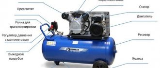
Last time we painted airbrushing (on 2110) - powering the airbrush from a paint compressor, but this is not convenient for many reasons:
-the paint compressor does not have a control relay (I’m writing about the one I have), and if there is excess pressure in the receiver, it releases it through the valve. When painting cars, this is normal, since the air consumption of the spray gun is quite large, and the time to apply a layer of paint - even an entire car - is a matter of 20-30 minutes. With airbrushing, everything is different - the air consumption is negligible, the pressure of the painting compressor is even excessive for it, and the time count goes on in days. In principle, since we have more than one receiver, we simply turned off the compressor and worked with them (15-20 minutes), as soon as the pressure dropped, we turned it on again (for 2-3 minutes), but this is also inconvenient - so how the pressure was constantly changing. You can, of course, install a pressure regulator, but it will not fundamentally save the situation. And it’s stupid to turn on a powerful, power-hungry and noisy compressor for the sake of an airbrush;
- since the painting compressor is huge and is powered by 380, there is no way to move it and paint - for example, at home - in a workshop, not in a garage, and in winter, heating the garage in order to paint for a couple of hours in the evening is also not practical. At first I thought of buying a special compressor - but all cheap compressors are outright rubbish - there is no pressure regulator, no receiver, not even a pressure gauge - I can’t imagine who would buy them at all. Professional ones cost as much as half my Kamryukha and even more, there is of course a golden mean, but I haven’t yet decided what exactly to take and decided to go on an adventure and do it myself, without investing from improvised means. In principle, there is nothing complicated here, you just need to get:
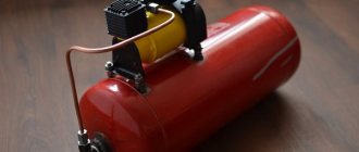
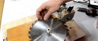
— compressor and electric motor (preferably together). Here I decided, as an experiment, to try using a compressor to inflate tires. There is already a compressor, an electric motor and a pressure gauge.
- a receiver is generally the simplest thing - you can use anything: I considered: a pneumatic cylinder from a truck or car, a gas cylinder for refilling air conditioners, or a cylinder from a water supply station. I settled on the latter – the reason for my choice is below.
- pressure regulator - I had it in stock, in principle it was possible to buy it.
— an airbrush with a hose. There was an air spray, the hose was used from a VAZ windshield washer.
— Well, and a bunch of all sorts of nuts, fittings and adapters.
The compressor for inflating tires was chosen as the most affordable, in principle, after testing it will become clear how convenient it is.
The receiver - in the form of a cylinder from a water supply station - was chosen because of its convenience and size, it is moderately large, has “legs” and an upper platform for installing a pump (and in the case of using a 12 V electric motor, a converter can also be placed there voltage), and it already has a connector with a car nipple.
But since everything was taken from what was there, it turned out to be rusty and, as it turned out later, it also had holes in the place where the flange was welded.
There was also no cap for this cylinder. It was decided to make it from a sheet of thick metal.
The necessary holes were made on a drilling machine. Then I found a suitable fitting for welding the pressure regulator, for fastening it - I used a nut from a household gas pipe to fasten the fitting, I could not find an adapter and used a fitting from a spray gun.
Since the place where the lid was screwed had micro cracks, after installing the plate, it was decided to glue this place with polyester resin. They smeared it, taped it with napkins, smeared it again and taped it again. Napkins - solely for the purpose of not spreading - while it dries.
Next, I left it all to dry for a day.
A day later, I check for leaks - everything is fine - no more micro cracks.
Then I picked up a couple of wires,
I connected the pump to the relay and screwed the relay to the receiver.
I connected the pump, put on the airbrush hose and connected it to the battery (for testing).
I turn on the pump and it pumps. I take a screwdriver and adjust the pressure regulator. The pump pumps up pressure and turns off, I release the pressure with the airbrush - it turns on again, I wait - it builds up and turns off.
I take the airbrush and release the pressure on the body element,
to understand whether there is condensate, oil, etc. in the air of the compressor. - it didn’t turn out. Later I repeated the same experiment on a “water mirror” - the same excellent result. Filters will be installed later, just in case.
After which I spread a little black paint and check the effectiveness, it’s good, but the pressure is not enough.
Using the regulator, I increase the pressure - it gets better. Several trial attempts - and it becomes clear that pressure in the range from 2.0 to 2.2 atm is necessary and sufficient. It is this range that allows you to hold this receiver perfectly, but if you constantly bleed air through a completely open airbrush, there is no longer enough air.
On the one hand, a constantly open airbrush is nonsense, on the other hand, there must be a reserve, and besides, when applying the background of the picture (more on this soon in the Camry BZ) - the airbrush works in exactly this mode. In principle, for such a case, you can connect it to a painting compressor or, for example, perform the work in two or three stages with breaks, but as a professional inventor I wanted to make a compressor with a power reserve.
Auto compressor modernization
You can make a mini compressor for connecting a spray gun or airbrush from a car pump, improving it a little. Modernizing the compressor will increase its power (performance) and will consist of adapting it to a voltage of 220 V (instead of 12 V), connecting the device to the receiver and installing automation.
Adaptation of the device to 220 V voltage
To connect the car pump to a 220 V network, you will need to find some kind of power supply unit (PSU), the output of which will be 12 V and the current strength suitable for the device.
You can find out the current consumed by the device by looking at its nameplate. In this case, the power supply from the PC (see figure above) will be quite sufficient in terms of current and voltage.
So, if you plug the electrical cord into your PC's power supply and turn it on, nothing will happen. This is explained by the fact that the power supply will not turn on until it receives a signal from the PC. To simulate turning on a PC, you need to insert a jumper on the connector coming out of the power supply. You will need to find among the many conductors one wire that is green and the other wire that is black, as shown in the following photo.
These wires can be cut and twisted, but it is better to short them with a jumper.
Next, you need to find 2 more wires at the output of the power supply: one yellow, this will be “+”, and one black with the polarity “-”. You can take any wires of these colors from any bundle of conductors.
Since the car pump has a plug for connecting to the car’s cigarette lighter, you can cut it off and connect the device with the corresponding color wires from the power supply.
But it will be better if you buy a car cigarette lighter and connect it to the power supply, and connect the device itself using a standard plug.
There are 3 wires coming out of the cigarette lighter: red – “+”, black – “-” and yellow – “+”, intended for connecting the LED. Connect the conductors to the cigarette lighter, observing the polarity (see photo below).
If you insert the plug from the device into the cigarette lighter, you will get a 220 V electric air compressor, capable of not only inflating tires, but also working with an airbrush.
Connecting additional elements
To connect the device to the receiver, you need to assemble the structure shown in the diagram below.
This harness includes the following elements.
- Crosspiece having all outputs with BP1/2. The marking means: “BP” - internal thread, “1/2” - thread diameter in inches.
- The tee has all outlets with HP1/2 (“HP” - external thread).
- Valves in the amount of 2 pcs. (BP1/2 – BP1/2). Designed to block air movement in both directions. Double marking means that there is an internal thread on both sides of the valve.
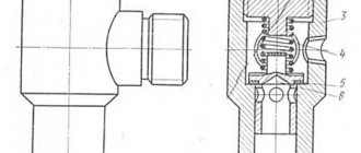
- Check valve. Designed to allow air to flow in one direction only. You can install a simple spring valve BP1/2 - BP1/2. If you plan to work with a pressure of 6-7 bar, then it is necessary to select a check valve that does not have plastic parts.
- A straight nipple is an adapter with 2 external threads (HP1/2).
- Transition nipple HP1/2 – HP1/4. Allows you to change from one external thread diameter to another.
- Extension (60 mm) HP1/2 – HP1/2. This is the same nipple, only straight. That is, the thread at both ends has the same diameter.
- Transitional coupling. It is an adapter from an internal thread of one diameter to an internal thread of another. In this case, from BP1/2 to BP1/8.
- A tee having all outlets already with HP1/8 thread.
- Direct coupling VR1/8 – VR1/8. Has 2 identical internal threads.
- Adapter for HP1/8 hose.
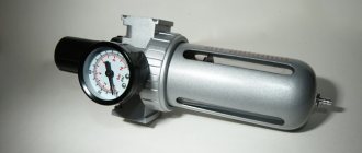
- Pressure regulator (pressostat) with moisture-oil separator. The pressure switch allows you to maintain the air pressure in the receiver not lower than the minimum and not higher than the maximum permissible level. A moisture separator may not be installed if the unit will be used as a tire inflator. When using the unit for painting, installing a moisture-oil separator is a must.
The above piping diagram assumes 2 outlet fittings: the first for venting air to the spray gun (airbrush), and the second for inflating tires.
- Transition nipple HP1/4 – HP1/8.
- The fitting (HP1/4 - BP1/8) is an adapter from a larger diameter external thread to a smaller diameter internal thread.
- Pressure gauges. These devices allow you to visually monitor the level of air pressure in the receiver and at the supply to the main line.
When assembling all elements, it is necessary to use thread sealant, for example, fum tape. Pressure gauges can be connected via cut-offs of high pressure hose. The latter should be pulled onto the adapters and secured with clamps.
Pressure gauges can be screwed directly onto the thread, without using hoses, if you do not need to display them on the front panel of the unit.
What the compressor piping looks like when assembled according to the diagram is shown in the following photo.
The receiver for a car compressor can be made from a large-diameter metal pipe welded on both sides, a fire extinguisher or a gas cylinder. If the compressor is supposed to work only with an airbrush, then a regular tubeless wheel from a passenger car can serve as the receiver.
Important! When selecting a container for the receiver, you should take into account the fact that the car pump can operate for no more than 10 minutes. continuously. Accordingly, the volume of the receiver should be small (about 20 liters) so that the device can raise the air pressure in it to the required level before 10 minutes have passed.
Stationary receivers
In the first case, the receiver is a separate sealed tank, for which a special stand or legs are provided (Figure 1).
Such models are placed on a pre-prepared base, most often a concrete floor or slab. The base must be level and strong to withstand weight pressure and possible vibrations. Stationary receivers are used in enterprises where the production of compressed air is required on an ongoing basis.
Refrigerator compressor
An air compressor made from a refrigerator, or rather, from its unit, is the quietest. But you should know that such a device is not characterized by high performance. With its help, you can only inflate car tires or work with an airbrush. For the normal operation of various pneumatic tools (screwdriver, grinder, spray gun, etc.), the performance of this unit is not enough, even if you connect a large volume receiver to it. Although on the Internet you can find designs consisting of two or three compressors connected in series, connected to a large receiver.
So, the unit removed from the refrigerator has a starting relay with a power cord. There are also 3 copper tubes coming out of the device. Two of them are intended for air inlet and outlet, and the third (soldered) is for oil filling. If you turn on the device for a short time, you can determine which of the two tubes sucks in air and which one blows it out.
The following figure shows how to assemble the entire structure, consisting of a unit, a receiver and a pressure regulator with a pressure gauge.
An air filter is installed on the inlet tube to prevent dust from entering the unit. To automate the air pumping process, you can install automation in the form of a pressure switch.
Mobile receivers
If the room area is limited, or compressed air is required at remote sites, in such cases, mobile compressor units with a built-in air collector are used (Figure 2).
In this case, the receiver on the trolley is located in a horizontal position, together with the piston compressor on top.
There are other design features. So, there are receivers:
- Vertical design.
Vertical air collectors are most often stationary models, the installation of which significantly saves space in a cramped room, especially if several receivers are connected to the compressor. Due to their vertical arrangement, condensate is removed from the bottom of the tank faster and more fully. However, the vertical location of the receiver requires a sufficient height of the premises where it will be used. - Horizontal receivers
allow you to place an electric motor, pump and auxiliary equipment (in case these are mobile units). Such models have compact dimensions and less weight than vertical ones, so they can be installed on a chassis and transported to the desired location. A characteristic feature of this arrangement is the minimum length of connecting pipelines and maximum resistance to external influences.
DIY high pressure compressor
The high pressure compressor (HP) is made from a two-stage compressor head AK-150.
A 380 V motor with a power of 4 kW can be used as a drive. The rotation of the engine shaft is transmitted to the piston group shaft using an eccentric, which also serves as a drive for a plunger-type oil pump. It creates an oil pressure of about 2 kgf/cm2.
Compressed air, leaving the last stage, enters through an adapter with an installed pressure gauge into the fitting of a liter cylinder, which is installed in its lower part. A valve for draining condensate is also installed here. The cylinder is filled with ground glass chips and acts as a moisture-oil separator.
Air exits from the top of the cylinder through a finger fitting. The compressor is cooled by water. After 45 min. When the unit operates, the water heats up to 70 degrees. The author of this unit claims that during this time you can pump 1 8-liter cylinder and 2 4-liter cylinders to 260 atm.
How to connect a receiver to a compressor?
To increase the efficiency of working with compressed air, many compressor units use receivers - containers for storing air under pressure. Based on the intensity and volume of work, containers of 50, 100 liters, sometimes more, can be used. In this article we will look at how to make an additional receiver for a compressor with your own hands, why it is needed in general, and what characteristics should be taken into account when assembling it.
What is the receiver for?
The receiver is required for the compressor to perform the following functions:
- The receiver accumulates compressed air, which helps reduce vibrations in the system. This in turn reduces the load on the base and reduces the noise level from a permanent installation;
- Stabilizes the air pressure supplied directly to the work area. In this case, differences in pressure are inevitable, since the operation of any compressor involves the injection and suction phase of air;
- Air purification from condensate. Otherwise, due to the increased pressure, the air humidity would also increase, which would lead to corrosion of the steel surface of the compressor;
- Provides compressed air supply when connecting an additional consumer, as well as during interruptions in the operation of the compressor.
To obtain large volumes of compressed air, a standard receiver may not be enough. For example, for sandblasting large surfaces, instead of a more powerful compressor, an additional receiver .
In addition, an additional receiver makes it possible to use the compressor less often, thus reducing energy consumption!
Deciding on the parameters
In addition to capacity, the compressor receiver can be characterized by the following parameters:
- Requirements for the location (within air contaminated with mechanical particles, for example, near circular saws, away from explosive, flammable materials and heat sources).
- Working conditions (relative air humidity should not be more than 75-80 percent, temperature around 15-40 degrees).
- Maximum air humidity levels.
According to the requirements of PB 03-576-03, it is prohibited to use receivers that have defects on the surface, such as corrosion, dents and cracks, as well as those that have not passed the performance test of the container walls.
The characteristics of the receiver for the compressor are selected as follows. The first step is to determine the maximum and minimum pressure values, the duration of operation and the required compressed air consumption. The next step is to find the required data using a table with online calculations, which can be easily found on the Internet upon request. For example, in the case of a maximum/minimum pressure drop of 4/3 atm, a maximum load duration of 5 minutes and an air flow rate of 0.1 m 3 /min, the optimal volume of the receiver tank will be 500 liters.
This method focuses on the time during which the receiver will be completely empty. However, there is a simpler tabular method that allows you to correlate the power consumption of the compressor with the volume of the receiver. Among them, it is worth highlighting the most commonly used ratios:
- Up to 550 liters for compressors up to 20 kW;
- Up to 300 liters for 10 kW models;
- And up to 100 liters for 5 kW products.
If necessary, intermediate values can be calculated by interpolation. There are also experimental dependencies. According to one of them, the capacity of the receiver tank should not be less than the compressor performance during 8 seconds of continuous operation. In this case, the volume of the tank at an air flow rate of 400 l/min can be calculated as follows:
V = (400*8)/60=53.33 l
Rounding up we get 54 liters.