Classification of lathes with a copier
The machines are widely used in the woodworking industry. Important aspects of the classification are process manufacturability and design features. There are many different models available, which can be divided into four categories:
- Classic. A cutter is used as a cutting tool. The machines are not designed for large-scale mass production.
- Copying. They work according to templates that make the task easier when creating similar variants. In small-scale production, models with manual control are in demand.
- Milling. We are in demand for the production of volumetric and flat workpieces.
- CNC. Units with numerical control are required in large quantities when supplying expensive models.
Copy wood lathes are equipped with improved characteristics and are therefore in demand for use in workshops.
Features of operation and safety precautions
The operating principle of copying and turning equipment is simple:
- the blank of the future product is clamped in a horizontal position;
- the machine is started, which rotates the workpiece around an axis;
- the cutter removes excess wood from the workpiece, giving it the required shape.
To avoid injury during work, you must follow basic safety rules:
- Do not expose or remove the workpiece from operating equipment.
- Do not lean or press against the machine while working.
- Remove chips only with a special brush.
- The machine must not be left unattended during operation.
- The technician must wear safety glasses to prevent chips from getting into his eyes.
A turning unit with a copier is successfully used both in large mass production and in home workshops for the manufacture of identical products. You can make such a machine yourself, having an unnecessary hand router, a sheet of plywood and horizontal bars of a certain size.
Classic machine design
The machines are equipped with a sophisticated design system. These include CNC models that operate in an automated mode. Such devices are obtained by using drawings and a copying device. The classic design consists of five nodes:
- The main element is a metal frame; individual parts are connected by welding. The bed has different heights, so when creating a homemade machine, this particular parameter is selected.
- The front and tailstock are needed to store the box, drive and electric motor. The rear one fixes the workpiece to obtain dimensional parts.
- An electric motor and drive rotate the workpiece.
- A tool rest is needed for the best quality work. The cut site is protected to prevent injury.
- The master and slave centers secure the part.
A homemade lathe-copier for wood makes it possible to carry out high-quality cutting of workpieces no worse than production models.
Copying machine from scrap materials
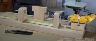
Hello everyone, I bring to your attention such an interesting homemade product as a copying machine. Using it, you can almost fully automatically make axes, handles for knives, swords, make baseball bats, make gun butts and much more. All you need is to clamp the finished product and a piece of block from which the copy is cut into the machine. Well, then you can go about your business, the machine will do everything itself! And when the product is ready, the machine will turn off on its own. Making such a machine is not at all difficult, but its usefulness is even difficult to evaluate; it is priceless. The design is very simple; the main tool is a grinder with a wood cutting disc. Most of the parts used are borrowed from domestic cars. As for additional materials, this is a corner for the frame, plywood and other little things. So, let's take a closer look at how to make such a machine!
Materials and tools used by the author:
List of materials:
— VAZ wiper motor (2101-2107 or similar); — driving and driven sprocket from the bicycle; - bicycle chain; — grinder with a disc for wood; — two pumps from VAZ 2108 (VAZ parts from China); — timing belt VAZ 2108; — belt tensioner VAZ 2108; - steel corner; — switch (installed under the VAZ brake pedal); - metal corner; - plywood; — bearings, washers, bolts and nuts; - square pipes; — threaded rod (for the shaft).
List of tools:
- Bulgarian; - drill; - hacksaw; - welding machine; - wrenches, etc.
Copy machine manufacturing process:
Step one. Making the base
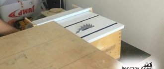
The base for the machine should be quite strong. The author used a steel corner as a material. The design turned out to be rectangular in shape. We cut the corner to the required size, and then assemble the frame using bolts and nuts or simply weld everything together.
Next, you can install the side walls. All important nodes will be placed on them. The material should be quite strong. For these purposes, you can use plywood, or it is better to glue several sheets together. OSB can also be used. In total we need two walls; we fasten them with three bolts and nuts, each on a base.
There are 3 holes in the side walls, one central one is needed to install the working shaft. This shaft has a thread and a carriage with a working tool rides on it. And the other two holes are needed to install the original part, as well as the workpiece from which the copy is made.
Step three.
Assembling the “thrust wall” There are two stops on the thrust wall, the length of which is adjustable. With the help of these stops we will fix the original part and the workpiece. Here you will need steel pipes, rods and so on. You can come up with your own design for these stops.
The working shaft bearing is also installed in this wall. You need to cut a hole for it, and the bearing is fixed using two washers, which are installed in front and behind the bearing. The washers are tightened using three bolts and nuts. We tighten this whole thing thoroughly and move on to the second wall.
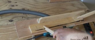
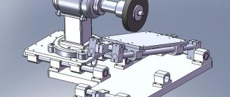
Step four. Drive Shaft Installation
Our drive shaft is a threaded rod. It rides on a carriage on which there is a grinder with a cutting disc. We select two corresponding nuts for the shaft and weld a bracket to them for installing the angle grinder. We select the desired distance, length, and so on. The author assembles the bracket itself from square pipes, steel plates and other parts. There is nothing complicated in the design, you just need to select the dimensions as you go. A lever is welded to this entire structure, which rests against the original part and, when rotated, transfers its contour to the workpiece, and the grinder cuts out a copy. You also need to install a bearing for the shaft in the main wall. We screw the shaft itself to the bearing with nuts so that it does not move.
Step five.
Driven Pulley To get low speed on the main shaft, we need to make a driven pulley. To make it you will need plywood. To obtain the desired thickness, you can glue several sheets together. You can turn the pulley on a lathe or simply on some suitable engine. Using a flange, we attach the pulley to the shaft and secure it with nuts.
Step six. Holders
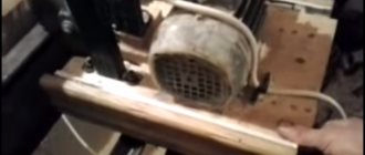
Now we need to install two holders that will hold and rotate the products. For these purposes, the author has successfully adapted two pumps from a VAZ 2108. We drill holes for them and install the pumps with impellers inside the machine, screwing them with bolts and nuts. We will need the pump impellers themselves in order to conveniently secure the products. The author modified the impellers using a grinder so that teeth appeared on them.
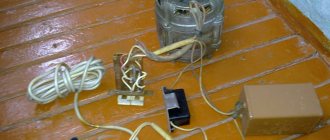
Step seven. Engine
To rotate the working shaft you will need a small motor; for these purposes, a motor with a gearbox from windshield wipers is perfect, in this case it is a part from a VAZ 2101 car. The author initially welded the motor shaft directly to the machine shaft, but in the end it turned out that the speed was too high and later the design has been redone, read about it below. You can use a steel angle for fastening. However, if you learn to regulate engine speed, then this option is also viable.
The author modified the pump impeller a little; he used a grinder to cut teeth on them. As a result, it has now become convenient to clamp the workpiece and the original part. Let's start installing the working tool, in this case it is an angle grinder. A special clamp is fitted for it. Well, we also install a cutting wheel for wood. It is advisable to use carbide-tipped wheels; they last longer.
Step nine. Downshift
When testing the machine, the author discovered that the working shaft rotates too quickly. To solve this problem, it was decided to make a reduction gearbox. For these purposes, the author adapted a chain drive from a bicycle. We cut off the connecting rod from the drive sprocket, and weld or screw a flange to the driven sprocket. We install a small sprocket on the motor, and a large one on the working shaft. That's all, now screw the motor through the corner to the frame and install the chain. We get low speeds and high torque, which is what we need.
Step ten. Adjustment and testing
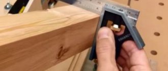
You can test the machine; to do this, install the original part in the lower part, in our case it is an ax handle. Next, we need to adjust the lever that rests on the original workpiece. We adjust its angle by unscrewing the nut and bolt, then tighten them in the desired position.
We install a block in the upper part of the machine from which the handle will be cut. Well, then you can start the car. We supply 12V to the engine and the working shaft begins to rotate. Next, we tilt the grinder a little so that the disk does not lie on the tree when starting, and turn it on. As a result, the process of copying the product begins.
Step eleven. A little automation
When the machine is finishing its work, it will need to be turned off in time, otherwise the carriage will hit the wall and break it or something worse. To make the machine safe and convenient, we need a switch that will automatically turn off the device when the job is completed. To do this, you will need a switch, which is located in the car under the brake pedal. But this switch will need to be connected via a 220V relay. We drill a hole for it and install it in the right place.
That's all, now you can start the machine and go about your business, it will turn off itself when the work is finished!
Become the author of the site, publish your own articles, descriptions of homemade products and pay for the text. Read more here.
Homemade wood turning and copying machine with your own hands
Industrial types of copiers are not cheap, so craftsmen choose the option of constructing a homemade machine. It requires little investment of money and effort.
Performance generally depends on the specifications of the copier. The main task of a self-made device is to create parts according to a template without additional energy consumption.
Required Tools
You won’t need many tools; all of them are publicly available and available to every master:
- Manual frezer.
- The cutter is placed on a support, which can be made of plywood 12 mm thick. Metal is used to improve performance. The dimensions of the platform are about 50x20 cm.
- Bolts.
- Thrust bars.
- A pipe with a diameter of 25 mm will allow you to set the direction of movement of the support platform.
The fundamental cutting tool when constructing a lathe with a copier is considered to be a hand cutter. Even though the copier is made of plywood, it is capable of creating many copies.
Features of the unit
A milling machine for metal or wood works using the following rules:
- The cutting element in this type of equipment is a milling cutter. It creates the desired contour or volumetric elements in accordance with the established software specifications;
- There is another connecting element between the cutting element and the tracking device. This is a supply and control system, which can be mechanical (used in the simplest units that process wood), hydraulic or pneumatic;
- As a copier, a specially created template, outline drawing or a ready-made part is mainly used. CNC copy-milling machines do not require such samples, so they are considered universal. These units operate thanks to numerical commands that are specified by the user through a special interface.
- templates can be blanks made from any materials - wood, metal, plastic, etc.
Disadvantages of the device in question
Along with numerous advantages, the copier has minor disadvantages. Among them:
- The working surface is guided by hand, because during operation it can jam or warp.
- It is possible to copy simple details.
- To move the tool, it is recommended to choose a helical gear type.
- For universal qualities, it is recommended to replace the cutter with a circular saw.
Thus, to copy complex parts, it is better to install industrial types of equipment. Homemade options are suitable for workshops.
Milling options
Milling on a copying machine can be carried out using one of two methods:
- Up milling , in which the part is fed in the opposite direction from the cutter.
- Climb milling , in which both the workpiece and the cutter move in the same direction.
Milling methods
The cutter on such devices can be made of mineral ceramics, synthetic or super-hard material and can replace the grinding procedure. But for machines working with wood products, this is not very important, since this material is not particularly hard.
Safety precautions when working with a turning and copying machine
Following the advice of experts when working with a copying lathe will make it possible to avoid numerous unpleasant situations and damage:
- Always check the fastening of elements and protective parts.
- It is necessary to remove unnecessary objects from the machine.
- Tools must be in their place.
- The cutting tool is checked for correct sharpness and proper design.
- The feeding of the equipment is carried out smoothly and without pressure, only after reaching the full rotation speed.
If any malfunctions occur, it is recommended to contact a specialist or carefully inspect all components.
Types of milling machines with copying function
Copying machines can have different drives. On this basis, this equipment is divided into:
- units where a pantograph is present. Allows you to copy at the desired scale. The equipment where the pantograph is installed can process parts in several directions. The design of this unit includes a spindle pin and an axis of rotation. The pantograph provides the required scale of processing due to a certain ratio of distances between these elements;
- copiers that are equipped with a working mechanism mounted on a rotary rack;
- devices with single or multiple spindles that have rotary tables of various sizes and shapes;
- units with different supply schemes - mechanical, hydraulic, electrical;
- photocopying installations.
Depending on the degree of automation of all operations and the method of fixation, this equipment can be:
- desktop, where the workpiece is secured mechanically;
- stationary, where parts are fixed using pneumatic clamps;
- stationary with pneumatic clamps and a three-spindle head.
Do-it-yourself copying machine for a router
Purpose and characteristics
Equipment for wood turning operations has reduced power and weight compared to metalworking devices, but has no less functionality.
Woodworking lathes offered by Stankoff.RU are used both in small home workshops and in large enterprises that require turned wood elements for the manufacture of products. The need to buy a wood lathe from our catalog comes from craftsmen whose activities involve creating parts for the production of carpentry, furniture, decorative finishing elements and souvenirs. The workpiece is usually cylindrical parts or timber with smoothed corners. During the rotational movement of the workpiece and the translational feed of the cutting tool, the material is processed using one of the main operations:
- longitudinal, axial or frontal trimming and turning of workpieces;
- drilling holes and shaped profile boring;
- production of openings and grooves;
- thread cutting;
- processing the end parts of parts, rounding corners;
- surface grinding.
Depending on the modification and technological equipment, wood lathes are used to manufacture parts of complex configurations or are used to create simple household utensils, decoration elements and souvenirs. Processing makes it possible to produce products of symmetrical cylindrical or conical shape using turning of the outer and inner surfaces of the element. Tabletop wood lathes differ from floor-standing models in several ways and have:
- lower power levels and electric motor speeds;
- limited by the maximum dimensions of the workpiece being processed;
- simplified method of switching rotation speed;
- limited range of additional accessories.
Design and operating principle of turning equipment
The stable base of the wood lathe is mounted on a cast iron bed, which ensures stability during operation by compensating for vibrations produced by the device. The headstock and tailstock racks are attached to the frame, and the caliper and electric motor are located. In models with electric drive, the motor is covered by an aluminum casing. The equipment mechanisms are not subject to overheating, so the machine does not have a coolant supply system.
A working head with a special device for fixing the cutting tool is installed on the headstock. The spindle is connected to a drive pulley, which transmits the motion energy from the electric motor. Replaceable faceplates for fixing the workpiece have different sizes to allow you to work with parts of different diameters. Before fixing the workpiece on the spindle, the holes necessary for fixing the part are drilled at the ends of the blank. This helps make the shaft rotate more evenly.
If desired, a lathe for woodworking can be equipped with a number of additional devices that can significantly expand the capabilities of the equipment when working with wood:
- sets of cutters, chucks and adapters;
- copier;
- equipped with a variable speed transmission for smooth speed control;
- a set of supports to prevent deflection of the workpieces.
DIY making
A homemade wood carving copying machine, of course, cannot fully compete with industrial designs.
When using homemade devices, various disadvantages are observed. The most common problems are vibration of the machine frame, sagging of the workpiece, and large errors when copying. Therefore, when designing your own machine, you should take into account the tasks that it will solve. It is easier to assemble a narrow-profile device than a universal one, immediately setting it up to solve the same type of problem.
Despite the variety of diagrams showing the order of assembly of the machine, all devices have the same basic components.
The minimum set of elements is as follows:
- Working desk.
- Bearing frame.
- Milling head.
Rotation from the electric motor is transmitted through the drive to the head with the cutter. If it is necessary to change the cutting mode, the height of the table changes. If desired, a transmission mechanism is developed to change speeds.
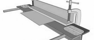
The pantograph can be assembled from wood or metal.
The wood pantograph has its drawback, since the wooden parts are connected using hinges and, thus, they are characterized by backlash. Therefore, the processing accuracy of a wooden pantograph is low.
When making a metal pantograph, it becomes possible to create copies of different scales. But he doesn't know how to make large copies.
Some craftsmen are trying to remake an ordinary production milling machine by adding a copying device to it. In this case, it is necessary to remake almost the entire old machine and it is easier to assemble the unit from scratch.
The size of the workpieces that the machine will have to process should be taken into account. The greater the length of the workpiece, the greater the load on the guide axis of the machine. They may not be able to withstand such a load. And also when working with large parts, the tool experiences large vibrations. To compensate for the moment of vibration, the equipment must be designed massive and heavy.
Therefore, first of all, before creating a copy milling machine for metal or wood, you need to highlight the tasks that will be solved when working on it. Based on this, the dimensions of the table and the entire structure, methods of attaching the template and options for moving the cutter are planned.
If you plan to process flat parts, then two machine axes will be enough for contour copying, since the movement will only be longitudinal and transverse.
If you expect to work with embossed workpieces, you will need to add a perpendicular movement.
If the relief is large, then you have to rely on one more axis - the fourth.
All possible options must be thought through before starting production of the machine, since after manufacturing and assembling all the components, it is very difficult to make changes to the existing design.
The layout of the machine can be horizontal or vertical. If the machine is vertical, then during milling the chips fall either onto the table or into a special tray, and do not settle in the parts of the cutter.
For better quality of product processing, the milling head must be high-speed.
To process parts made of different materials, it is advisable to have a set of cutting cutters of different quality and wear resistance.
After determining the range of tasks, the required motor power is calculated. To perform engraving and similar work on wood, a motor with a power of one hundred and fifty to two hundred watts is sufficient.
The working unit and the probe are fixed together so that they are on the same plane and height in relation to the working table. A rigid clamp is used as fastening. Then the entire assembled element will be able to move parallel to the sides of the working surface, both horizontally and vertically.
All moving parts must be as light as possible so that control forces are minimal.