How to make a plane with your own hands simply and effectively
In order to carry out work with curved or concave bases, they came up with humpback moulders, which are used to produce textured planing of wooden blanks. These elements have a special shape. They do not have any special advantages in comparison with planes. In addition, such devices are quite problematic to work with. In order for parts to be processed efficiently, it is necessary to gain some experience in such work, as well as special skills.
Today, it is very difficult to find moldings in construction stores, since almost all stores sell electronic equipment. It is for this reason that it is much easier to make a plane yourself.
The iron element will determine the dimensions of the homemade plane body, therefore, first of all, it is necessary to start manufacturing the iron element, as well as the chip breaker. For a plane of small dimensions, you can take an iron element from an old product, and for a device with oval-shaped elements, you can purchase “pieces of iron” at any hardware store. Such devices are initially filled along the radius; you can buy them together with suitable chip breakers. The planer drawing is very simple and understandable; almost anyone can create it.
Selecting and processing the workpiece
In most cases, planes are made from the most common types of wood - maple, birch and others. The workpiece should be made 30-50 millimeters larger than the final dimensions of the device being manufactured. The width can be determined using the following formula: dimensions of the “piece of iron” + 3 mm + on the cheeks 20 mm + additional 6 mm for the possibility of processing on the machine. If the plane is made of small dimensions, then the cheeks may have a thickness of approximately 6 mm.
The marking of the tool should be done so that the rings are parallel to the sole, and the fiber goes down to the back from the front. So that after sawing all parts of the structure can be connected correctly, a triangle should be drawn on the front of the block, the apex of which points upward.
First of all, it is necessary to make two parts of the middle section, between which the “piece of iron” and the chip breaker are secured using a wedge. Then you need to secure 2 cheeks.
The body of the plane is assembled from a blank, which is sawn into two parts. The cheeks are cut out with a band saw. Then the middle section is sawn into several elements. At the same time, it will be necessary to make the bed of the iron element, as well as the distance for the chip breaker. You can cut a wedge from scraps that will no longer be used. Upon completion of assembly, the sole and body must be processed into shape. Finally, the plane is adjusted.
Note that the middle element should be 1 mm wider than the “piece of iron”. In addition, take into account an allowance of 1 mm for processing the middle part of the tool to a rectangular shape. The cheeks can be marked using a saw. We place the iron bed at an angle of 45 degrees, so the chips can come out without any difficulties. The front opening entrance is positioned at an angle of 60 degrees. I saw the middle element into the front part - the toe and the back part - the heel.
Then you need to make a simple template from plywood sheets, with which you select a groove for the screw head, it ends approximately 20 mm from the bottom of the case. The groove can be selected with a chisel.
Tool pre-assembly
When making a homemade plane, you need to lightly process the mouth of the middle element with a file, using the outline of the “piece of iron”. Then the back part of this section is installed on the edge, the iron element is put in place, and then the front part is moved towards it. Finally, you need to check that the fit is correct.
After this, the structure is moved apart so that between the components of the middle element of the plane there is a gap of 3 mm for the “piece of iron” with a thickness of 4.5 mm, which forms the mouth of the tool. Next, all parts of the structure will need to be aligned and compressed. You will need to drill holes through the cheeks in the middle section on the two sides so that dowels can be installed and glued.
It is worth noting that a significant part of the planes are rectangular in shape, so you should not waste time refining the structure.
In the side parts you need to choose small holes for your fingers; if they are present, it will be convenient to hold the tool. The corners must be chamfered.
Once the plane has its final shape, you will need to cut off the chamfers. Until then, they will be able to ensure that all parts are accurately aligned so that adjustments can be made to the crossbar. To ensure that the dowels do not interfere with the parts of the structure when gluing them together, it is necessary to saw them off flush with the cheeks.
Completion of tool manufacturing
Round spikes will need to be mounted on the extreme parts of the rod; they will fit into the holes in the cheeks. Thanks to these spikes, the structure will be able to rotate at an angle to the wedge. To make holes for the rod on the top element of the plane, an additional line should be drawn at an angle of 90 degrees to the side parts. After that, 1 cheek is removed from the assembly, and with the “piece of hardware” and chip breaker installed, the line is transferred to the other cheek. The second cheek is removed from the middle part and the center of the hole intended for the rod is marked at an interval of 20 mm from the bottom of the tool and 12 mm from the top of the chip breaker.
Note that in order to guarantee the exact location of the rod hole, it must be made using a drilling device.
The cheeks are aligned along the drawn lines, then they are compressed with clamps, after which a hole is drilled.
You can make a rod from timber, which has a cross-section of 12*12 mm. The length of the rod should be equal to the width of the structure, taking into account the cheeks. The length of the spikes is determined based on the thickness of the cheeks. Four shoulders must be made at the ends of the rod. Next, the spikes are rounded with a knife.
In order for the chips to exit uninterruptedly, you need to round off the upper ribs of the middle part of the rod. After the rod is ready, you need to check its fit to the tool. The rod should rotate without problems.
Final assembly of the element
about a small wooden plane with your own hands
After adjusting the rod, you need to check the location of the dowels and tenons. These parts of the structure must be flush with the cheeks. All parts will need to be glued and secured with clamps, while the cheeks must be protected with gaskets. When the glue dries, you need to start cleaning the protruding solution. To be able to level the sole over the joints, you need to go over the product once with a planer.
A wedge can be made from cuttings from the middle part; it must be installed between the rod and the chip breaker. If the wedge is flat in shape, it will be difficult to knock out. If the angle is too large, then the wedge can be knocked out even with minor blows.
After the plane is assembled, it will be necessary to make the sole and remake the mouth in order to finally fit it to the iron element, taking into account the purpose of the product being manufactured. A narrow gap in front of the “piece of iron” is a prerequisite in order to remove chips thinly. And a gap of 0.8 mm wide is more suitable for coarse chips.
The most labor-intensive part of making a plane is fitting the tool’s mouth to the “piece of hardware.” The taphole must be rounded according to the bends of the iron element. This can only be done through a small opening in the sole of the plane. If the product is made for removing thin chips, then care must be taken to ensure that the mouth gap is as narrow as possible.
The iron element should be secured to the uneven line of the front of the middle element, after which you should begin to give the correct shape to the sole. To do this, you need to clamp the product being manufactured in a vice with the sole up and from the ribs to the middle, where you need to remove some wood. Then the structure must be processed with a plane with a flat sole.
When there is a distance of 0.8 mm left in the plane to the radius of the “piece of iron”, you need to switch to the scraper. This is done so that marks from the planer can be removed. Then, fine sandpaper is fixed to the plate and the lower part of the plane is cleaned with long, identical passes, while rocking the tool from side to side. Then the contours of the sole of the “piece of iron” are examined. Upon completion, you should clean the sole with micron sandpaper, which is attached to a flat base.
After stripping, the piece of hardware will not be able to pass through the mouth of the product. For this reason, it is necessary to remove the wood in front of the “piece of iron” with a small file. Remove until the iron element coincides with the mouth. As a result, the “piece of iron” should come out a little from the sole.
If you are satisfied with the quality of the product made, then the instrument can be varnished. It is recommended to apply an additional layer of varnish to the sides of the plane.
Please note that when gluing all parts of the product, it is necessary to promptly remove all excess glue that may stick out after being compressed in the vice of the plane.
Making a plane from wood is not difficult if you take into account all the available nuances. It is necessary to follow the correct procedure and also have all the necessary materials and tools.
Which produce magnificent carpets at low prices, I recommend placing an order here uz-carpets.ru
With many years of experience working with wood, I have developed plane designs that can be used to plan hardwood finely and cleanly without cutting out.
My planes are different from ordinary ones. Firstly, I believe that when planing more or less smooth surfaces, a chipbreaker is not needed, since in my opinion the quality of planing is affected by the cutting angle, the width of the slot of the block and the sharpness of the cutting edge of the piece of iron. Secondly, my planes have a larger cutting angle than is generally accepted (about 65°) and a very narrow slot (about 0.25 mm).
On some planes, to provide a thin edge and prevent wear in the slot area, I attach a brass plate to the sole.
Because of the very low blade output, my planes work better on flat surfaces. But they are heavier than usual, and the pieces of iron become dull faster. That is, they turned out to be specialized planes, although in practice they can also plan soft wood.
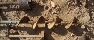
Making a plane is quite simple. The block consists of three oak parts (photo 1). The central part of the block is 1.5 mm wider than the iron to ensure lateral adjustment.
A tap hole and a narrow slot - a “mouth” (photo 2) are marked on it at the desired angle, and then the block is sawn into two parts, preferably on a band saw.
The taphole must be planed to obtain a flat surface - a “bed” (photo 3). This is a decisive stage in the manufacture of the plane, since in order to facilitate adjustment of the plane and work with it, the taphole must be free of cracks and at right angles to the side planes.
After checking, part of the block with the tap hole is glued to one of the sides (photo 4). Then, ensuring the required width of the slot, the front part of the block is glued. To do this, holding the piece of iron on the bed with your hands, install and press the front part of the block into place (photo 5).
The slot must be narrower than the design one, even if a brass plate is installed on the sole. Then glue the other side of the block (photo 6). When the glue is completely dry, to get the gap of the desired width, sand the sole with light passes. After this, to ensure that the block is exactly rectangular in shape, smooth out the remaining sides and trim the ends (photo 7).
Mark the installation location for the pin that secures the wedge (photo 8), drill holes for it (photo 9) and insert a piece of oak dowel Ø10 mm onto the sliding fit.
Finally, slightly round the ribs so that the block fits comfortably in your hand (photo 10). If you need to install a brass plate on the sole, cut out a corresponding groove for it on a circular saw (photo 11). (Don't forget to pull out the piece of iron!).
All my planes are similar to the Japanese ones, the edges of which are slightly rounded for ease of work, but not so much that they are shapeless. Some planes are equipped with Japanese-type iron, which does not require either a wedge or a pin holding it (photo 12).
I work with most of them “on my own,” but, unlike Japanese planes, my planes can also be used “for myself.” To do this, I install the piece of iron so that the front and rear parts of the block are almost the same in length.
A little about my method of sharpening iron. I sharpen it only on two whetstones: with very fine grain and for finishing razors. I make the point by touch, and it usually takes no more than a minute. In addition, I believe that during work you should have several sharpened pieces of iron so as not to waste time on sharpening.
Based on materials from the magazine: “Do It Yourself” (Author of the idea: Seth Yanovsky)
- It doesn’t matter what kind of surface planer you have: home-made or factory-made. We'll show you how to get this traditional marking tool ready for use.
- Looking to remove small bevels on the edges of a table top or drawer face? This is easy to do by grinding, but it is difficult to achieve clarity and uniformity, and using a router will require
- At the first stage of tool sharpening, a chamfer with a profile groove is usually formed on the grinding wheel (Fig. 1). On the second, the cutting edge is sharpened and tucked on a whetstone. Sharpened and circles. When turning
- A tongue and groove tool is a carpentry tool designed for cutting a narrow rectangular groove - a tongue and groove on the edge or face of the carpentry piece being processed at a given distance from its edge. In progress
- It is difficult and dangerous to file the pads on a band saw for subsequent turning. To make this work easier, a device is made that resembles a rolling carriage for logs on a sawmill.
For a lot of people, working with wood is enjoyable. It’s nice to make a table for the veranda yourself or make a bench for the garden. You should know that this is a lot of physical work. However, today the work can be much simplified by using electric planes. Anyone can work with such a tool, even a beginner.
Such a device appeared quite a long time ago. Externally, modern electric planers resemble old designs, but in terms of productivity they are several times superior to mechanical designs.
Using an electric planer, you can process wood, reduce the thickness of wood blanks, plan, adjust, process boards on a bed, and bevel edges. With this device it is not possible to process large surfaces, but in the case of small volumes it makes sense to use a similar tool.
A plane is primarily intended for leveling a wood surface that has previously been roughly processed. After leveling the base with this tool, all irregularities and defects will disappear from the product, as a result of which it will become extremely smooth. Finishing wood in most cases is done with a sanding plane. Using this tool you can also make a groove or chamfer in a part.
How to make a plane with your own hands?
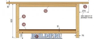
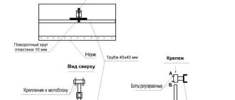
Figure 1. Diagram of planer elements.
In order to work with concave or curved bases, humpback moulders were invented, with the help of which they produce textured planing of wood blanks. These elements have a special shape. They have no particular advantages over modern planes. In addition, working with these devices is quite difficult. To produce high-quality processing of parts, you will need to have some experience and special skills.
Today it is very difficult to find molding in construction stores, since almost all stores sell electronic equipment. That is why it is much easier to make a plane yourself.
Items you will need to make your own plane:
- Iron element.
- Chip breaker.
- Wood preparation.
- A simple pencil.
- Wedge.
- Band-saw.
- Plywood sheet.
- Chisel.
- File.
- Adhesive mixture.
- Drilling device.
- Clamps.
- Beam with a section of 12x12 mm.
- Planing machine.
- Micron skin.
A homemade plane with junction points for all elements can be seen in Fig. 1.
The iron element will determine the dimensions of the tool body, so the first step is to make an iron element and a chip breaker. For a small plane, you can use an iron element from an old tool, and for a plane with oval-shaped elements, you can use ready-made “pieces of iron”, which can be purchased at a hardware store. These devices are initially filled along the radius, they can be purchased complete with suitable chip breakers.
Return to contents
How to select and process a workpiece?
In most cases, the plane is made from the most common types of wood - birch, maple, etc. The workpiece must be made 30-50 mm larger than the final dimensions of the tool being manufactured. The width can be determined by the following formula: dimensions of the “piece of iron” + 3 mm + 20 mm on the cheeks + additional 6 mm for processing on the machine. If a small plane is made, then the cheeks can be approximately 6 mm thick.
The marking of the tool must be done in such a way that the rings are perpendicular to the sole, and the fiber runs down from the front to the back. So that after sawing all the elements can be connected in the correct order, you will need to draw a triangle with the vertex up on the front of the block.
First of all, you will need to make 2 elements of the middle section, between which you will need to secure the “piece of hardware” and the chip breaker using a wedge. After this, 2 cheeks are attached.
The tool body is assembled from a blank, which is sawn into 2 parts. The cheeks are cut out with a band saw. Next, the middle section is sawn into several parts. At the same time, it will be necessary to form the bed of the iron element and the opening of the chip breaker. A wedge can be cut from unused trim. Once assembly is complete, the body and sole must be machined to shape. Finally, the plane is adjusted.
The middle element should be 4 mm wider than the “piece of iron”. In addition, there should be an allowance of another 4 mm for processing the middle structural element to the shape of a rectangle. You can mark the cheeks using the same saw. The iron bed is placed at an angle of 45° so that chips can come out without difficulty. The tap hole of the front opening is located at an angle of 60°. The middle element is sawn into a front part, which is called the toe, and a back part, which is usually called the heel.
Next, you will need to make an ordinary template from plywood sheets, with the help of which you select a groove for the screw head, which ends at a distance of approximately 20 mm from the bottom of the case. The groove can be selected with a chisel.
Return to contents
Pre-assembly of the structure
Before assembling the plane, the mouth of the middle element must be lightly processed with a file, using a “piece of iron” shape. Next, the rear part of this section is installed on the edge, the iron element is applied in place, after which the front part is moved towards it. Finally, you need to check that the fit is correct.
Next, the structure is moved apart so that between the parts of the middle element of the structure a gap of 3 mm is formed for the iron element 4.5 mm thick, which forms the mouth of the instrument. After this, all parts of the plane will need to be aligned and compressed. You will need to drill holes through the cheeks in the middle section on 2 sides in order to install dowels and glue them.
In most cases, planes are rectangular in shape; you should not waste time refining the structure. You should choose small niches for your fingers in the side walls. To make it easier to grip the tool, you need to chamfer the corners.
When the plane has its final shape, the chamfers will need to be sawed off. Until this point, they will be able to ensure that all elements are accurately aligned so that the crossbar can be adjusted. To ensure that the dowels do not interfere with the process of gluing the tool elements, they need to be sawed off flush with the cheeks.
Return to contents
Completion of the structure
On the extreme parts of the rod you will need to install round spikes that will fit into the holes in the cheeks. Due to these spikes, the structure will be able to rotate at an angle to the wedge. To be able to make holes for the rod on the top of the plane, an additional line must be drawn at right angles to the side parts. Next, 1 cheek is removed from the assembly, and with the iron element and chip breaker installed, the line is transferred to the other cheek. The second cheek is removed from the middle part and the center of the hole for the rod is marked at a distance of 20 mm from the bottom of the structure and 12 mm from the top of the chip breaker.
To ensure the exact location of the rod hole, you will need to make a hole on the drilling device.
The cheeks are aligned along the drawn lines, compressed with clamps, and then a hole is drilled.
The rod can be made from timber with a section of 12x12 mm. The length of the rod should be equal to the width of the tool, taking into account the cheeks. The length of the spikes is determined based on the thickness of the cheeks. At each end of the rod you need to make 4 shoulders. After this, the spikes are rounded with a knife.
To ensure uninterrupted chip flow, the upper ribs of the middle element of the rod will need to be rounded. After making the rod, you will need to check its fit to the tool. The rod should rotate freely.
An industrial design costs a lot of money, so here we will try to figure out how to make a jointing machine with our own hands, using a household electric hammer.
Manufacturing algorithm
To assemble the device with your own hands, adhere to the established plan. The sequence of actions looks like this:
- To create a support, a rectangle is cut out of metal. Markings are made on it for the drum and mounting holes;
- Steel corners are screwed in on all sides of the slab with bolts and then welded;
- From the remaining corners, cut out 4 legs for the plane;
- The resulting racks are welded to the corners of the slab;
- A rack for the motor is assembled from steel strips. It is attached through holes in the support;
- The seams are being cleaned;
- The plate is removed;
- The upper parts of the corners are welded so that there is no space between them;
- The resulting seams are cleaned with a grinder or file;
- The stove is put in place;
- Under the slot, a drum and bearings are placed on clamps or brackets;
- The engine is secured in the desired position (the shaft must protrude);
- Pulleys are installed on the shaft and drum;
- A belt drive is installed;
- The engine is installed in such a way that the belt tension is sufficient;
- A plywood or tin casing is created. It is attached with screws to the corners so as to cover the belt and motor;
- The case is covered with plywood at the location where the start button is installed, then the button itself is installed;
- A capacitor is installed if necessary;
- Assembling an electrical circuit with your own hands (power cable, button, machine, capacitors);
- The first test run of the device takes place.
After starting work, the master pays attention to the direction of rotation of the drum. It should be carried out in the same direction from which the wooden blanks for planing are fed.
Various designs of jointing machines
Structurally, jointing equipment manufactured in industrial conditions is very different from machines made independently. They differ in the materials used, technologies, auxiliary equipment, etc. But this does not mean that a homemade jointing machine made from a simple electric planer will not be in demand for home use. It is quite suitable for processing small parts in small quantities.
There are two main types of wood planing machines:
- Single-sided machines (the production of this option will be discussed). With such equipment, only one surface can be processed in one pass. Structurally, these are the simplest devices;
- Double-sided or two-spindle. Such a device can simultaneously process two adjacent surfaces of a part. It is quite difficult to make such equipment yourself.
In addition to the above types, you can also add that machines can be both stationary and mobile.
main idea
Yes, such a homemade jointing machine, unlike serious industrial designs, has a number of disadvantages, namely:
- Cannot boast of high processing accuracy;
- The width of the workpiece is very small - only 110 mm;
- Lightweight is a disadvantage, since a heavy massive base always gives the device stability and, as a result, ease of use, which ultimately improves the quality of the result.
- Low power, limited by the power of a household electric planer;
- The body material is wood, that is, not durable;
However, it also has undeniable advantages that make it very useful for achieving certain goals and performing a number of tasks, since it has the following advantages:
- Low cost - serious jointing machines cost tens and hundreds of thousands of rubles, and the cost of this homemade jointing machine consists of the cost of the plane and materials;
- Compact and portable - it can easily be stored anywhere in the workshop and can be deployed for work in a matter of minutes.
- The simplicity of the design affects its reliability and maintainability.
- The ability to make the necessary dimensions of the machine “to suit you”, for example, you can increase the length of the work table or change the height.
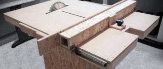
Budget Workshop Part 2: Planers
To begin with, you should clearly understand the difference between a carpenter and a joiner.
Both of them work with wood. A carpenter makes furniture, some small household items, more precise and beautiful. A carpenter is a worker who makes some simple products such as boxes, pallets, benches and more complex ones - houses and gazebos. It is clear that it is not always easy to clearly separate these professions. When I started working with wood, I thought that I really needed an electric planer. This is great, whack - and everything is smooth. And I bought it for myself. And only then did I realize that an electric planer is a tool for carpentry, and it is not suitable for carpentry. I have two now and I can't say when I last used it. This is too rough a tool. No, of course, they can do something, for example, remove excess “meat” from the workpiece and so on. But I can get by with a saw for this.
What am I talking about? And besides, if we previously sawed the tree into blanks, now we need to level them. And for starters, a plane works very well for this. There are many different types of planes. But we’re talking about budget carpentry, right? This means we need a universal, inexpensive plane. For this, I advise you to look for a metal plane from the Sestroretsk plant, the so-called Voskovsky. It is easy to recognize by the logo on the case.
These planes are copied from the original Stanley ones and are quite pleasant to use. I bought my first one at a flea market for 500 rubles. It is better not to buy any stamped planes in stores, just like inexpensive Chinese cast iron ones. They are either non-working or require efforts to put in order that beginners cannot do. What to look for when purchasing? First of all, check the sole to see if it is worn out, if it is even, if there are any cracks on the body. This is the basis of the plane. Apply a ruler and look at the light. I would advise a beginner to pay attention to the hardware, since you want to work right away, and not sharpen it. But most likely you will have to sharpen it. The so-called five is most often sold - this is the tool that is most often needed.
There is a lot of video material on setting up planes. I most often use two planes, one of which is configured for minimal material removal, and the second for rougher roughing. It’s easier for me, I don’t need to waste time setting it up. For a beginner this may be important. In general, I have a lot of different planes. In the photo there are only some Voskovites. I don’t work on all of them; many need to be brought to fruition.
Working with a plane is a pleasure. Layer by layer is slowly removed, the surface becomes smooth, and translucent shavings curl. There is no whine of power tools, just the quiet whoosh, whoosh. Instead of fitness, you can level the boards. What I mean is that you have to work physically.
And to work with a plane you need a heavy base. It won't work on a stool. Moreover, the base should not only be heavy; a simple table will fall apart and become loose very quickly. Previously, sand was poured into workbenches. Or you can screw it to the wall. I most often clamp small workpieces in a simple bench vise, for which I made plywood jaws.
You need to straighten a crooked board, for example. If it is very crooked, then it is better to saw off the edge on a saw, it’s easier. This is how I lay out the meter ruler and draw with a pencil everything that needs to be removed. I immediately work on high places, and then along the entire plane.
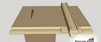
The bottom may be useful for leveling the ends. This simple design allows you to get a predictable, even angle, as it works against the stop. We rest the workpiece and forward. You can do the same for a 45 degree angle, which is very difficult to saw off exactly. And then the plane slides along the bed and cuts little by little. And it doesn’t chip at the exit, since the stop there prevents the chip from breaking off.
Preparing the necessary accessories for work
To make a jointing machine with your own hands, you will need materials, equipment and tools, namely:
- Manual electric planer. Will be used as a woodworking tool. It is best to use high-quality, branded Makita or Bosh power tools - this is an additional guarantee of productive, long-term work;
- With . Alternatively, you can use a regular hand jigsaw, since we will only need it once to make one part;
- co or drill;
- or any other . Alternatively, you can use a simple handsaw;
- Wood screws (3.5x40 or 3.5x45);
- 10-15mm, for tables and other small parts, 18-20mm - for the side wall of the bed. Alternatively, you can use or, but this is an extremely undesirable option;
- Solid wood for making a side support, approximately 15-20mm thick.
This is an indicative set of what you might need to make a homemade jointing machine.
Homemade machines from an electric planer
Thicknesser from an electric planer
A thickness planer is a woodworking equipment that is used to plan even planes of lumber until the desired thickness is achieved. In this case, only pre-prepared (coated) boards or beams are processed.
Preparation of materials and working tools
There are quite a lot of different options for creating structures that allow you to convert an electric planer into thicknessing equipment. relatively simple homemade machine at home,
- screwdriver with a set of bits;
- carpenter's square or corner;
- tape measure or simple ruler;
- screwdrivers with different tips;
- spanners;
- electric plane;
- jigsaw or hand saw for wood;
- plywood with a sheet thickness of 1.5 cm;
- long screws with coarse threads (4 pieces);
- bicycle chain and four drive sprockets for it;
- wooden blocks (2.5 by 2.5 cm) and planks (1.5 × 1.5 cm);
- nuts with M14 thread;
- washers of suitable sizes;
- screws 25 by 100 mm.
The electric planer will serve as the main mechanism of the created machine. The screws can be replaced with wood screws of similar sizes.
Manufacturing algorithm
Drawings and diagrams will help to simplify the process of creating a thicknessing tool from an electric planer, but it is easier to do it from photographs. The equipment is manufactured in the following sequence.
- A rectangular fragment is cut out of a sheet of plywood, having a length of 50 cm and a width of 40 cm.
- It is used to assemble stands for an electric plane mounted on a working platform from pieces of plywood, which are secured to each other with self-tapping screws or self-tapping screws.
They create a working platform for installing an electric planer on it. To do this, use a jigsaw to cut an opening in the prepared rectangular piece of plywood in the shape of the power tool being used (as shown in the photo below).
- Using special clamps, which often come with an electric planer, as well as screws, fix this tool to the working platform.
- A drive mechanism is mounted on the base using screws, which will ensure its raising and lowering. Threaded screws with asterisks are installed at the corners of the platform.
- Using screws, install the platform base onto the stand made for it.
- In a convenient place, the thicknesser position control handle is attached to the long screw using nuts and washers.
- The created is configured and tested .
- cut out the base for the machine from the existing sheet material;
- a stop for the workpiece is attached to it using self-tapping screws or screws at an angle strictly of ninety degrees (a square is used to set it);
Install a measuring bar (ruler segment) and an index arrow.
The created structure is installed on a flat surface. To fix it to a workbench or table, you will need to use suitable fasteners.
The presence of a drive mechanism makes it possible to set the required thickness of the workpieces being processed.
When assembling the machine with your own hands, you should fix the cable supplying the power tool so that it does not interfere with operation, and the wire is not accidentally damaged. To securely fix the electric planer itself on the work site, it is recommended to use bolts and nuts.
The measuring ruler is a mandatory structural element of the homemade surface planer being created . With its help, the thickness of the lumber that is planned to be processed is determined. A piece of plastic, wooden or metal ruler 8 cm long is suitable as a bar. You can also make a pointer arrow from similar materials.
Assembling a jointing machine based on a jigsaw
A jointer is designed to remove existing irregularities from the surface of wood. The work process consists of one-sided planing of lumber along a plane. You can also shoot at different bevel angles. Thanks to processing on this equipment, beams or boards become smooth.
The design of the jointing unit is simpler than that of its thicknesser counterpart. This allows you to assemble the installation yourself using available materials.
The procedure for making a jointer
To make a planer for processing small-sized workpieces, you will need an electric plane that can be fixed in a stationary position. The base of the created unit can be a fragment of plywood, MDF or chipboard. A piece measuring 50 by 35 cm is sufficient. The thickness of the sheet material used should be more than 2 cm.
Assemble the jointing tool by performing the steps in the following sequence:
- install ribs that will ensure rigidity of the stop;
- An electric plane is attached to the base using M8 bolts and nuts.
Before fixing the stop, a hole is cut out in it for the pipe and for cooling the electric motor of the tool.
If you need to plan large workpieces, then it is enough to increase the size of the unit being created. This will result in a design as in the photographs below.
In addition to the considered option from an electric planer, jointing equipment can be assembled in another design. The practical implementation of such designs depends on the materials and creativity available to the home craftsman. How to make homemade jointing units of other designs is shown in the following videos:
Making a stand for an electric planer
When working with an electric planer constantly, it is recommended to have a special stand that is suitable for storing it and installing the tool on it immediately after turning it off.
The use of such a device is especially important when working with powerful, heavy electric planes.
To avoid holding the instrument in your hands the whole time the drum stops, you need to use a stand of a special design . The main element is a groove approximately 8 cm wide and 0.6 cm deep. It is necessary for the drum to rotate freely until it stops completely. The accuracy of the position of an electric plane placed on a stand (when the blades are above the cut groove) is ensured by the presence of a front stop made of a strip.
The width of the groove and the distance from its front edge to the stop are determined by the dimensions of the power tool model used in the work.
Required tools and materials
To make a stand yourself, you will need the following tools:
- an electric jigsaw equipped with a file for cutting out shapes;
- screwdriver with a set of bits;
- drill with metal drills 3 and 4 mm in diameter;
- awl;
- hand saw for wood with fine teeth;
- ruler or tape measure;
- square;
- pencil or marker;
- spherical wood cutter ;
- sandpaper;
- chisel (enough with a 3-4 centimeter tip width).
To create the structure you will need the following materials:
- a piece of board up to 1 m long, 20 mm thick and 140 mm wide;
- wood screws – 2 pieces 4 by 45 mm;
- wooden plank 30 mm wide, 20 mm thick, and 140 mm long;
- 4 self-tapping screws with large heads 4 by 15 mm.
It is recommended to prepare all tools and materials in advance before making the stand, so as not to be distracted by small details during the work process.
Machine parts
Let's look at the main structural elements:
| Name | Description and purpose |
| Machine base | The bottom part of the machine where everything is mounted. |
| Side wall | The supporting structure of the machine, which serves to mount the electric planer and both tables. |
| Rear table (fixed) | Together with the front table it forms the plane of movement of the workpiece. Attached to the side wall. |
| Front table (adjustable height) | Together with the back table it forms the plane of movement of the workpiece. Attached to the side wall. |
| Fixed on the back table. Used to give direction to the movement of the workpiece. | |
| Spacer corners (stiffening ribs) | They serve for general strengthening of the structure, as well as to support a given 90-degree angle. |
| Electric planer | The main element of workpiece processing. |
Making a homemade jointing machine
Side wall
First of all, we will make a side wall, for this we use plywood 18-20mm thick with dimensions 150x480mm. By cutting out a place in the workpiece in which the electric planer will be fixed. This should be done using an electric or manual jigsaw, since the sample shape has a complex configuration.
Front movable table
The front table, which must be adjustable in height, is made of two rectangular pieces fastened at an angle of 90 degrees. For greater structural strength, you need to make triangular stops between them. In this example, everything is attached with self-tapping screws; however, for greater strength, it is recommended to coat the joints with wood glue. The end result should be a design like this.
At a distance of 70 mm from each other, you need to make two through holes with a diameter of 8-10 mm and hammer furniture drive nuts into them. It is better to do this before assembling the base.
Installation of the movable table is done using two screws on the back of the side wall. For convenience, you can use bandages with a winged head or make homemade holder mounts. The installation should be carried out so that the plane of the moving part of the “sole” of the electric planer is in the same plane as the movable table of the jointer.
The side stop is needed to ensure smooth and parallel movement of the workpiece, as well as to establish an exact 90-degree angle between the work table and the stop plane. The stop is made simply - from two parts, which can be made from either plywood or solid wood. In this case, an array is used.
A do-it-yourself jointing machine made from an electric planer is ready for use.
Construction drawings
Drawing of a homemade electric planer
The workpiece to be processed should be fixed on the surface using ten bolts to a pre-prepared frame (it needs to be welded from corners).
A groove is cut into it for the drum and a square (attached with M8 screws) for stability. The planer drum is fixed upside down under the table with M6 screws using bearings and fasteners. The device will move by means of a belt drive.
Safety when working with homemade equipment
When working with any tool, you must follow safety precautions, as ignoring them can cause various injuries. We will briefly list the recommended measures to ensure the safety of the master’s work on this machine.
- It is recommended to remove sharp chamfers and sand all manufactured parts to eliminate the possibility of hand injury (splinters, etc.)
- When working, it is necessary to use a chip extractor or a special vacuum cleaner, for example, a cyclone type, to remove sawdust and dust from the sawing area, which can cause the following harm:
Homemade plane: drawings and description
In the current age of innovative technologies in production, hand tools are rarely used, and in mass production of products they are not used at all.
However, there have always been, are and will be craftsmen - cabinetmakers, for whom working with wood is not only part of their business, but also their favorite pastime. For them, making a product with their own hands is always a pleasure. Such specialists have a lot of hand carpentry tools in their workshop.
Types of planes
A plane is a hand-held tool for working wood, allowing you to bring the surface of a product with your own hands to the required quality and size. Having the entire set of types of this tool, you can not only process the surface, but also make various carpentry crafts.
The planer has a whole arsenal of types:
Flat planing:
- sherhebel;
- jointer;
- semi-jointer;
- mole cricket;
- sander;
- tzinubel;
- end;
- single;
- double.
Figure planing:
- zenzubel;
- federgubel;
- folding belt;
- stabgobel or stabgaltel;
- tongue and groove;
- mold;
- primer;
- humpback
Having a full set of hand tools, if desired, you can make works of wood of any complexity. At the same time, an important factor for successful work is sharpening planer knives with your own hands, which is an expensive production service.
Among the figured planes, the zenzubel stands out with its useful features. It is used for making grooves, quarters, stripping and bringing tenons and cuts to the desired size. The manufacture of this type of instrument will be discussed.
The article outlines an algorithm for how to make a plane with your own hands.
Planer device
During the evolution of the plane, quite a lot of its varieties have appeared, which can not only process the planes of wood, but also be used for figured cutting. To enjoy manual labor, you need to be able to choose the right plane, and then you will get real works of art from an ordinary piece of wood.
Modern planes can be divided into wooden and metal models. Each of them has its own advantages and disadvantages, but in terms of design, the instruments are similar, like twin brothers.
A standard plane consists of the following parts:
- sole, also known as body;
- cutter;
- wedge;
- slot for chip exit;
- cutter clamp;
- cutting depth regulator;
- horn - front handle;
- emphasis - rear handle.
The key element of the design is the cutter - this is a cutting tool made in the form of a pointed plate.
The blade is positioned at a given angle to the surface being processed. Thanks to the regulator, the knife extends to a certain distance, which allows you to finely adjust the depth of cut and the thickness of chip removal. In factory models, the blade sharpening angle is standard, but professional carpenters change it depending on the type of wood being processed.
The handles also play a certain role. The front one, called the horn, performs a guiding function and usually has a curved shape that provides a better grip on the hand. The rear one is a stop, thanks to which the force necessary for work is created.
With the sole, which can be wooden or metal, everything is not so simple. The main criterion for this structural element is a perfectly flat surface.
If this requirement is not met, it will be difficult to use a hand plane, and you can simply forget about planing accuracy. Taking these nuances into account, a metal sole looks preferable: it is made according to a template, so a priori it has the correct geometry. However, mistakes made by the manufacturer during casting reduce these advantages to zero. Moreover, the metal is susceptible to corrosive changes.
A wooden sole is lighter, and if deformed, you can straighten it yourself, breathing a second life into the plane. However, wood is not a durable material; it is subject to mechanical wear and loses its original properties when exposed to moisture or high temperatures for a long time.
Despite the standard design, there are more than 10 types of planes, and each tool performs a specific function when processing parts. Let's take a closer look at these products.
additional information
All the tools listed above are standardized products. Therefore, in order for them to perform their job correctly and accurately, they must be manufactured in accordance with the requirements of GOST 15987-91. Below are extracts from GOST that define the basic requirements.
Materials
List of required materials from which you should make a hand plane with your own hands:
- ash;
- maple;
- hornbeam;
- white acacia;
- birch (allowed).
The wood must be well dried, without knots, cracks or rot. To glue parts, you must use waterproof glue.
Requirements for the metal used
Knives are made from the following types of double-layer steel:
- the main layer is made from grade 30, GOST 1050 (U8, U8A, U9 are allowed, GOST 1435);
- cladding layer - from grades 9ХФ, 9Х5ВФ, Х6ВФ, 9ХС, GOST 5950.
It is allowed to use metal of other grades, but no worse than those given in the standard. Knives must be perfectly sharpened and have an appropriate sharpening angle.
Advice: in order for the processed surface to be of decent quality as a result of the work of the tool, it is advisable to have a device in the workshop for sharpening a plane with your own hands.
Additional Assembly Tips
The metal for the stove is cut with a grinder or jigsaw. To cut a groove, it is convenient to use an electric jigsaw, having previously drilled a hole for its file in the slab, or an electric drill with an appropriate attachment. The edges of the slot are processed with a file so as not to get injured by them later.
You can secure the metal base plate with flat head screws (so that they do not interfere with work) or by welding it. The first option is preferable because, if necessary, the electric plane is easy to disassemble.
Before installing the drum, it is recommended to check the sharpness of its knives. If it is bad, then it is better to sharpen the blades immediately, using, for example, a regular whetstone. It is necessary to constantly ensure that the cutting attachments are well secured without distortion.
The basis for making your own knives are steel plates or hacksaw blades for metal, sharpened at an angle of 30 degrees.
The sequence of making an electric plane from a grinder with the working drum placed in a vertical position is demonstrated in the videos below. It also shows possible errors when assembling a homemade product.
https://youtube.com/watch?v=SY6xchF8VzU
Another option for creating a homemade electric planer from an old, non-working model is shown step by step in the video below.
Using the made power tool, you can process boards, beams and other workpieces. An electric planer assembled with your own hands must be used in compliance with safety requirements. The parts must be fed correctly to avoid getting your fingers caught in the drum.
There are many options for homemade electric planes. They have varying degrees of complexity, as well as different functionality. In this regard, the limitations are mainly related to the technical thinking of the inventors and the parts and materials available “at hand”. If necessary, the manufactured equipment can also be equipped with automation equipment.
Preparing for work
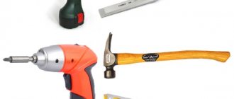
To make a plane with your own hands, you need to prepare the following tools.
Equipment and tools
| Name | Quantity |
| Ruler | 1 |
| Carpenter's protractor | 1 |
| Pencil | 1 |
| Reismus | 1 |
| Circular saw | 1 |
| Jigsaw | 1 |
| Drill | 1 |
| Drill, 10 mm | 1 |
| Joining machine | 1 |
| Miter saw | 1 |
| Band-saw | 1 |
| Vertical drum grinding machine | 1 |
| Milling machine | 1 |
| Finger cutter, 10 mm | 1 |
| Semicircular cutter | 1 |
| Chisel, hammer | 1 |
| Metal file | 1 |
| Clamps | 8 |
Materials and components
| Name | Type and dimensions, mm | Quantity |
| Metal knife | According to drawing | 1 |
| Light wood | Ash 270x100x25 | 1 |
| Dark wood | Oak 200x80x15 | 1 |
| Glue | Carpentry waterproof | 1 |
| Sandpaper | Grain 100, 500X100 | 1 |
| Sandpaper | Grain 600-800, 500X100 | 1 |
| Wood varnish | Colourless, waterproof | 50 g |
Additional Assembly Tips
The metal for the stove is cut with a grinder or jigsaw. To cut a groove, it is convenient to use an electric jigsaw, having previously drilled a hole for its file in the slab, or an electric drill with an appropriate attachment. The edges of the slot are processed with a file so as not to get injured by them later.
You can secure the metal base plate with flat head screws (so that they do not interfere with work) or by welding it. The first option is preferable because, if necessary, the electric plane is easy to disassemble.
Before installing the drum, it is recommended to check the sharpness of its knives. If it is bad, then it is better to sharpen the blades immediately, using, for example, a regular whetstone. It is necessary to constantly ensure that the cutting attachments are well secured without distortion.
The basis for making your own knives are steel plates or hacksaw blades for metal, sharpened at an angle of 30 degrees.
Hacksaw blade
The sequence of making an electric plane from a grinder with the working drum placed in a vertical position is demonstrated in the videos below. It also shows possible errors when assembling a homemade product.
Another option for creating a homemade electric planer from an old, non-working model is shown step by step in the video below.
Using the made power tool, you can process boards, beams and other workpieces. An electric planer assembled with your own hands must be used in compliance with safety requirements. The parts must be fed correctly to avoid getting your fingers caught in the drum.
There are many options for homemade electric planes. They have varying degrees of complexity, as well as different functionality. In this regard, the limitations are mainly related to the technical thinking of the inventors and the parts and materials available “at hand”. If necessary, the manufactured equipment can also be equipped with automation equipment.
Description of the manufacturing process
The material of the heel, nose and sole of the plane is ash. The cheeks and wedge are oak. The thickness of the plane should be equal to the width of the knife blade, 20 mm.
Then you need to cut a hole for the arm. For this:
- Using a drill, drill 10 mm holes for the file;
- Using a jigsaw, make a cutout for the hand along the marked contour;
- The inner surface of the hole is processed on a grinding machine.
If the workshop has mastered such an operation as sharpening a plane with your own hands, then the sharpening angle of the blade should be equal to 45 degrees so that the protruding cutting edge of the knife is parallel to the plane of the sole.
To do this, the oak blank is cut into two halves, and the surface and ribs are cleaned with a plane.
A cutout is made on the second cheek in the same way. A hole for the knife is cut out on both cheeks using a trim saw, hacksaw and chisel.
At the next stage, you need to glue all the parts into a single structure with your own hands. First, the nose and heel are glued to one cheek. To do this, carefully coat the parts with glue, apply them and press them with clamps. After drying, glue the second cheek on the opposite side.
After the glue has dried, the workpiece is finally cut along the contour on a band saw and the outer and inner edges are manually processed on a sanding drum. Using a semicircular cutter on a milling machine, all sharp edges of the plane workpiece are processed on both sides.
Finally, you need to carefully sand the entire plane blank by hand. Of particular importance is the quality of the sole, which is the working part of the tool. The cleanliness of the workpiece depends on its condition.
The flat sides of the workpiece are processed with your own hands, using sandpaper pressed against a perfectly flat surface. A jointer plate is suitable for this. First, sand with 100-150 grit sandpaper. The sole is brought to a “mirror state” with 600-800 grain.
Important! In order to check the quality of the surface of the plane with your own hands, you can use the thinnest feeler gauge to measure the gaps. The test is carried out on both sides of the sole.
The tool is coated with waterproof colorless varnish, and the do-it-yourself plane is ready.
Structural elements of a homemade electric planer
Electric planers appeared in the mid-20th century and became widespread. They have practically supplanted their manual counterparts. Thanks to their use, painstaking work has turned into more productive work. At the same time, the final quality of processing is high if this power tool is used correctly.
Factory products are represented by a wide variety of models, which, despite their different appearance, consist of structural units common to all. These electric planes work in two ways:
- using them as portable hand power tools;
- secured on a table or workbench in a stationary position (upside down - with the drum facing up).
The creation of a permanently fixed electric planer is considered the most suitable (simple) for independent practical implementation. The assembled device will have structural elements common to factory-produced products, such as:
- an electric motor, which is the drive mechanism of a homemade device;
- a protective cover that protects the worker’s hands from moving blades;
- on/off button;
- a drum with knives mounted on it, intended for planing wood;
- a transmission mechanism by which the movement of the electric motor shaft is transmitted to the drum with blades.
The role of the base of the homemade device will be performed by a slab with a flat surface, for example, made of metal, plywood or boards, or a table (workbench). In the latter case, you will not need to make legs for the machine. If the drum is attached to the stove, you will need to make a frame. It must be of a suitable height: match the height of the craftsman working with wood to ensure comfortable work.
What does an electric planer consist of?
A hand-made electric planer has the same structural elements as a factory tool. The parts of the plane include:
- electric motor;
- protective tool body;
- start button;
- knives on the drum;
- transmission mechanism.
Don't miss: How to sharpen a chisel at the right angle at home
Required materials and tools
Let's consider the manufacture of the simplest design, designed for a planing depth of up to 1.2 mm and a width of processed wooden workpieces of up to 120 mm. To assemble such an electric plane with your own hands, you will need the following materials and parts:
- bearings;
- steel strips;
- pressure plates;
- M6 and M8 screws with nuts;
- spring washers;
- metal corners (20x20x3 mm);
- staples;
- sheet of plywood (10 mm) or metal (3-5 mm thick);
- belt drive pulleys installed on the shaft of the electric motor and drum;
- a drum (with one or two knives) from an old planer or electric planer, on which you can change cutting attachments;
- a working electric motor from a grinder, an old electric plane or a planer;
- belt;
- button (switch) to turn the electric planer on and off;
- wires and cord with plug;
- residual current device (RCD);
- capacitors (if the electric motor used is three-phase).
Installing a separate RCD for an electric plane in the panel (even directly on the machine) will increase electrical safety when working with equipment. Protection is selected according to the power of the working engine. The cord and wires must be of a suitable cross-section, taking into account the power of the installed electric motor.
Phase shifting capacitors must be connected in parallel. In this case, the required total capacity is determined by the power of the installed electric motor: approximately 100 μF per 1 kW. Capacitors must be designed for mains voltage.
To implement the project you will need the following tools:
- several wrenches designed to tighten the nuts on the bolts;
- roulette;
- building level;
- marker or pencil;
- welding machine with electrodes;
- an electric drill with drills and a circle of small diameter intended for cutting;
- a jigsaw with files for it for wood and metal or hand saws for a similar purpose;
- angle grinder complete with wheels for cutting metal.
Algorithm for making an electric planer
You assemble an electric planer with your own hands by performing the steps in the following sequence.
- Prepare the base plate. To do this, cut out a rectangle of the required size from metal, make a slot in it for the drum using preliminary markings, and drill holes to secure it.
- Along the perimeter of the slab, steel corners are screwed using screws, which are then welded at the joints with each other.
- Cut 4 blanks of the appropriate length from the same corners for the legs of the equipment.
- Weld the cut posts to the corners fixed to the plate.
- They make a shelf for the electric motor from strips of steel at the bottom of the frame (taking into account the length of the belt), with pre-drilled holes for securing it and adjusting its position.
- Clean the welds.
- Remove the stove.
- Boil the upper joints of the corners that were located directly under the stove so that there are no gaps between them.
- The resulting seams are compared with the upper plane of the frame using a grinder or a file.
- Place the plate in place.
- Fix the drum on the bearings under the slot using clamps or brackets.
- Install the electric motor so that its shaft extends beyond the edge of the table;
- The pulleys are placed on the shaft of the electric motor and the drum.
- Install a belt drive.
- Adjust the position of the electric motor so that the belt is tensioned sufficiently.
- The casing is made from plywood or tin. It is fixed to the corners of the frame with screws, covering the belt drive and protecting the electric motor from debris, dust, and moisture.
- Sheathe the frame with plywood on the side where the start button is mounted and mount it.
- If necessary, attach a capacitor unit to the housing wall.
- Assemble the electrical circuit: connect the power cord, control button, circuit breaker and capacitors (if required).
- Conduct a test run of the equipment.
When starting a power tool, its drum must rotate in the direction from which the processed lumber will be fed.
Additional recommendations
There are some nuances to creating an electric planer. To do this yourself, adhere to the following rules:
- The metal plate is cut with an electric jigsaw or grinder. To create a groove, first make a hole in the slab, and then drill it with a jigsaw or electric drill. Go along the edges with a file.
- Flat head screws or welding are used to secure the plate. The first method is more convenient for do-it-yourself disassembly.
- Before attaching the drum, check the blades for sharpness. If necessary, they are sharpened on a stone.
- If you make knives yourself, then use steel plates or hacksaw blades for metal sharpened at 30 degrees.
Don't miss: Planer for aerated concrete: do-it-yourself, grinding aerated concrete blocks
After completing the assembly of the tool, it can be used on boards, beams and other objects. Be sure to follow safety precautions for planing. The parts are fed carefully so that your fingers do not touch the drum.
An electric planer is a useful tool in everyday life that can be purchased in a store or made with your own hands. There are a huge number of options and configurations for manual assembly. They differ from each other in the variety of available materials and difficulties during assembly. But the functionality of the devices is similar, the differences are only in ease of use due to the automation of the process.