Safety when working with homemade equipment
When working with any tool, you must follow safety precautions, as ignoring them can cause various injuries. We will briefly list the recommended measures to ensure the safety of the master’s work on this machine.
- It is recommended to remove sharp chamfers and sand all manufactured parts to eliminate the possibility of hand injury (splinters, etc.)
- When working, it is necessary to use a chip extractor or a special vacuum cleaner, for example, a cyclone type, to remove sawdust and dust from the sawing area, which can cause the following harm:
| To the Master | Respiratory and eye contact |
| Tool | Getting inside the instrument and:
|
| Process | Chips and sawdust getting between the workpiece and the table, resulting in poor fit and misalignment - the result is uneven processing. |
- When working, it is necessary to use pushers, since when working with small parts, it is possible that the master’s hands will get into the cutting zone, which will lead to injury.
Preparing the necessary accessories for work
To make a jointing machine with your own hands, you will need materials, equipment and tools, namely:
- Manual electric planer. Will be used as a woodworking tool. It is best to use high-quality, branded Makita or Bosh power tools - this is an additional guarantee of productive, long-term work;
- Jigsaw with files. Alternatively, you can use a regular hand jigsaw, since we will only need it once to make one part;
- Drilling machine with drills or drill;
- Circular saw or any other sawing machine. Alternatively, you can use a simple handsaw;
- Electric screwdriver;
- Wood screws (3.5x40 or 3.5x45);
- Plywood 10-15mm, for tables and other small parts, 18-20mm - for the side wall of the bed. Alternatively, you can use chipboard or OSB, but this is an extremely undesirable option;
- Solid wood for making a side support, approximately 15-20mm thick.
This is an indicative set of what you might need to make a homemade jointing machine.
Elements of a homemade tool
Electric planers were invented back in the middle of the last century and almost immediately gained popularity among builders.
They very quickly removed hand tools from the market due to high productivity.
Despite the absence of painstaking point processing, the plane allows you to perform the assigned tasks efficiently.
All modern models are quite different in appearance, but have common elements in the internal design. You can use an electric planer using one of two main methods:
- Use as a portable hand tool;
- In a stationary state, upside down (using reliable fixation on a workbench or table).
An electric planer that you can make yourself will have the same design elements as the factory models. Among them are:
- An electric motor that powers the tool;
- Protective cover (helps to save the operator’s hands from the sharp blades of the device);
- Start button;
- Knives mounted on a drum;
- Transmission mechanism (it helps transfer the rotational impulse from the shaft to the blades).
As a sole for an electric planer, it is allowed to use a flat slab (plywood, metal, boards), as well as a special workbench. The use of the second option is more preferable, since it does not require making legs for the machine. When using a stove, you will have to make a frame of sufficient height with your own hands. It must be suitable for the height of the planer operator so that it is comfortable to plane the wood.
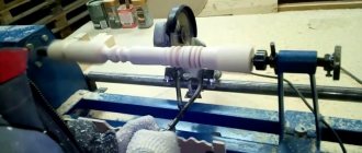
Professional homemade jointer
The figure shows drawings with detailed explanations. You will need a 1.5 kW electric motor connected to the shaft using a drive belt. You can make the knife shaft yourself or order it from a turner.
During the work, it is necessary to weld a frame from a metal profile or angle. Then the base plate and the base for the screw are welded to the frame. The side strips are attached to ensure free movement of the guides. To do this, you need to create technological gaps.
The lead screw is welded to the machine after it is installed on the support
. The equipment must be provided with a front plate, consisting of a top part and a guide rail. They are connected to each other by side elements. The end parts of the surfaces must be made parallel, after which they are carefully ground.
To ensure that the dimensions of the sidewalls installed on a homemade jointer are the same, they are processed and provided with holes for studs. After welding the sidewalls and guide elements, the temporary studs are removed.
At the last stage, the knife shaft is installed. At the same time, raise the front tabletop to its level so that the edge of the panel is parallel to the axis of the shaft. The back of the tabletop must be fixed in a stationary position. The center of gravity of this woodworking unit is high. To reduce vibration, it is recommended to additionally strengthen the jointers.
Every woodworking master will agree that an electric planer is a useful, and often completely irreplaceable, thing in a home workshop. With the help of such a manual machine, any wooden workpiece can be processed very efficiently, and most importantly, quickly.
Another indispensable tool for processing various wooden parts is a thickness planer. The cost of such equipment is now quite high, so it usually makes sense to buy it only if the craftsman will earn something from processing wood blanks. If such a machine will not be used for the purpose of earning money, but only to perform various tasks around the house, then the optimal solution would be to make a surface planer from an electric planer. It is quite possible to do such work even with your own hands. At the same time, the quality of the work performed when using such a homemade machine will remain at a fairly high level.
What is a thickness planer
In order to make blanks of the same thickness with maximum accuracy, thicknessing machines are used. The knife shaft in this device is located not at the bottom, but at the top. The workpiece is fed across the work table either manually, or it is fed onto the knives using special rollers.
The described machine levels the top of the board, making it parallel to the bottom. It follows from this that in order for the workpieces to be even and of the same thickness, they must first be leveled from the bottom side on a jointer. After this, you can level it from the top side using a surface planer.
There are both small, low-power models suitable for the home workshop, as well as complex, multifunctional and powerful industrial machines. The latter are often multifunctional. For example, there are planer-thicknesser machines on which you can level both sides of lumber and adjust all the parts to the desired thickness.
Do-it-yourself thicknesser machine made from an electric planer, other design options
Few people in childhood were left indifferent by their first visit to a carpentry workshop. The indescribable smell of fresh wood shavings, the cleanliness and smoothness of a freshly planed board, the fluffiness of sawdust - this is the place where, with the help of a thickness planer, the magical transformation of several clumsy boards with a scratchy surface from protruding fibers took place into an elegant stool.
The result of the surface planer was perfectly smooth lumber, which was suitable for making many interesting and beautiful things.
Design and operation scheme
The thickness planer consists of the following main parts:
- a horizontal table for processing various wooden parts and products (or a base made of a sheet of plywood, as in the homemade version);
- working processing knife shaft. One - in a single-sided design and two - in a double-sided design;
- pressure rollers responsible for feeding the part to the knife shaft;
- platform adjusting the height of the table;
- a fuse that prevents the workpiece from falling out of the machine. There is a risk of falling out if parts of different thicknesses are processed. In this case, a product of smaller thickness will hit the knife and jump out of the machine. To prevent this from happening, a special safety device is installed.
It all works like this: when the electric planer is turned on, it begins to rotate the blade shaft. The wooden part is placed in the gap and fed first to the lower and then to the upper rollers. The upper front roller is corrugated. Due to this, it grabs the part and transfers it to the knife shaft. In this case, the guides securely fix the workpiece and prevent it from falling out. After the product moves from the rear guide, the next workpiece is transferred to the front. And so on until all the details are processed.
Machine design
The jointing machine is equipped with a table. The table has a technological hole; a knife shaft operating from an electric drive is placed in it. During the planing process, lumber is fed onto the shaft using a roller mechanism. The support elements for the workpiece can be tilted at the required angle. The thickness of the board is adjusted by the tabletop by feeding it up and down.
The knife shaft can have a single-sided or double-sided design
. In the first case, one plane of the board is processed. The double-sided shaft allows you to joint wood from both sides at the same time. There is equipment with four knives that provide four-sided grinding. These samples are most often installed at large woodworking enterprises. The cleanliness of the processing depends on the diameter of the knife shaft. The larger it is, the higher the quality of grinding.
Two types of knives can be installed on a homemade jointing machine:
- Single-edged. Subject to periodic sharpening.
- Double-edged, disposable. When worn out, replace them with new ones.
Planers differ in shaft rotation speed, tabletop length, and planing width of lumber. The surface of the tabletop is divided into two transverse segments, with the front part located lower than the back to regulate the thickness of the removed layer of wood. The optimal cutting thickness is 0.5 cm. If more removal is necessary, several cycles must be performed.
For stability and improved load-bearing characteristics, the jointer frame is made of cast iron, and the frame is supplemented with steel plates. The knife shaft is fixed between the two halves of the tabletop. For convenience, the table is equipped with guide rulers.
Algorithm for making an electric planer
You assemble an electric planer with your own hands by performing the steps in the following sequence.
- Prepare the base plate. To do this, cut out a rectangle of the required size from metal, make a slot in it for the drum using preliminary markings, and drill holes to secure it.
- Along the perimeter of the slab, steel corners are screwed using screws, which are then welded at the joints with each other.
- Cut 4 blanks of the appropriate length from the same corners for the legs of the equipment.
- Weld the cut posts to the corners fixed to the plate.
- They make a shelf for the electric motor from strips of steel at the bottom of the frame (taking into account the length of the belt), with pre-drilled holes for securing it and adjusting its position.
- Clean the welds.
- Remove the stove.
- Boil the upper joints of the corners that were located directly under the stove so that there are no gaps between them.
- The resulting seams are compared with the upper plane of the frame using a grinder or a file.
- Place the plate in place.
- Fix the drum on the bearings under the slot using clamps or brackets.
- Install the electric motor so that its shaft extends beyond the edge of the table;
- The pulleys are placed on the shaft of the electric motor and the drum.
- Install a belt drive.
- Adjust the position of the electric motor so that the belt is tensioned sufficiently.
- The casing is made from plywood or tin. It is fixed to the corners of the frame with screws, covering the belt drive and protecting the electric motor from debris, dust, and moisture.
- Sheathe the frame with plywood on the side where the start button is mounted and mount it.
- If necessary, attach a capacitor unit to the housing wall.
- Assemble the electrical circuit: connect the power cord, control button, circuit breaker and capacitors (if required).
- Conduct a test run of the equipment.
When starting a power tool, its drum must rotate in the direction from which the processed lumber will be fed.
Making a machine yourself
To begin with, determine the number of functions of the future unit. It could be:
- just a planer with one planing operation;
- a combination of a jointer and a circular saw, which doubles the usefulness of the equipment;
- they add grinding, sharpening and drilling functions, but for your own workshop, making a complex set of equipment with your own hands is a difficult task.
Often, craftsmen independently make a jointing machine with a sawing function, while the torque is transmitted from one electric motor, which includes structural elements:
The bed can support the weight of the work plane and installed electrical and mechanical equipment. In a workshop, a channel with a shelf thickness of at least 10 mm is used to make the frame. The structure can be made stationary (welded) or provided with bolted components for disassembly if necessary. The first option is more reliable and is used if a portable machine is not needed. Sometimes the desktop itself acts as a bed. Working tools include knives and saws; the work of processing and sawing workpieces depends on their quality
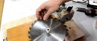
Reliable and strong steel is used for cutting blades; the saw teeth must be equipped with Pobedit tips. Without a rotor, to which all the tools are attached, not a single woodworking machine will function, so attention is paid to its selection. Most often it is made by a specialist turner according to the drawings offered to him. The design of the jointing unit with the sawing function provides three working surfaces - one serves as a table for the circular saw, the other two feed and receive the workpiece during the jointing process
Multilayer plywood, the thickness of which is at least 5 mm, or sheet metal, is used as a covering. Typically, the feed surface is made 2-3 mm below the receiving side to facilitate the process and reduce vibration load.
Electric drive of the machine
The operation of the jointer and saw is based on rotational functions, which is why the drive is called the heart of the unit. A three-phase motor is suitable as an electric motor; sometimes the wiring is re-equipped for this in the workshop. Three-phase units with a voltage of 380 V are characterized by high power and suitable torque. The minimum permissible engine power is 3 kW, the maximum is not limited.
The transmission of rotation from the engine to the shaft is carried out by means of a belt drive. V-shaped double-ribbed belts work well in such conditions; they are reliable in operation. The electric motor is mounted using a console inside the frame structure of the bed; the installation method helps to regulate the tension of the belts. Another way is to mount it using a slide - this still allows for adjustment, but the engine itself is more firmly fixed.
To accelerate the rotation of the shaft, two pulleys of different diameters are used. The larger one is placed on the electric motor, the smaller pulley is placed on the shaft. To supply electrical power, choose a cable with four cores; such wiring reduces the danger of operation.
Main stages of work
The progress of work in the manufacture of a jointing machine looks like this:
The first step is to draw up working drawings, without which there is no point in starting work. Sometimes you need to reconsider some node, change the size of a structural element, all this is first done on the plan, then on the machine. Dimensions from the drawing are transferred to blanks and all structural parts of the equipment are made
It is important to provide a place for the location of rotor bearings, which is made of several elements, using clamps and glue for connection. The recesses are made exactly according to the dimensions of the bearing, and the engine is installed. Complete the rotor with the bearing and install them
They make a belt drive and use it to connect the shaft to the engine, ensuring smooth and free rotation of the rotor in the bearing. A working surface consisting of receiving and supply parts is installed and finished with metal or plywood. For correct positioning in the horizontal plane, use a building level. They provide a starting switch and a switch for the electric motor; after a test run, the machine is ready for operation. To ensure its long-lasting performance, you should follow the recommendations for working with it.
Construction drawings
Drawings of the frame to which all the parts of the structure being created will be attached are given below.
The part being processed will rest on the surface of the plate, secured with 10 bolts to a frame welded from steel angles. There is a groove cut in it for a drum with knives. To guide the workpieces and prevent their lateral movement, a square is also attached to the base plate with M8 screws.
The shaft with knives (working drum) will be attached under the table top with M6 screws. To do this, bearings will be placed at its ends, which will be fixed to the plate with special fasteners. The movement from the electric motor to the working drum will be carried out due to a belt drive.
The motor is installed inside the frame on a shelf made of two steel strips, with holes drilled in them of the appropriate diameter for the frame mounting bolts.
It should be taken into account that the slots for the engine mounts (mounting grooves) need to be made several centimeters wide (2-3) in order to be able to tension the transmission belt.
The casing, fixed with M6 screws with spring washers to the corner, covers the belt drive. The power button is installed in a convenient place on the body of the electric plane.
When working with an angle grinder and drilling, you must wear glasses - they will protect your eyes from metal shavings. In general, when working with any tool, you should follow safety rules and use personal protective equipment.
What is needed to create
To get started, you need to prepare thoroughly.
Materials and tools
A homemade table will require a strong metal or wooden base. Some craftsmen prefer to make tables from aluminum or steel.
It is difficult to work with large volumes of wood with a regular circular saw, so it is better to place it on a table.
Important! The wood must be treated with a special agent that has an antiseptic composition to prevent rotting processes.
Materials that will be required during the work process:
- base, the thickness of which is at least 22 cm;
- beams for strengthening and making a support (you can use 5 pieces of edged board);
- wooden dowels, 10 cm in size (12 pieces or more are required for work);
- wood glue;
- metal fasteners (at least 4 pieces, and the exact number depends on the dimensions and length of the table);
- metal corners in the amount of 10 pieces;
- self-tapping screws
Before work you need to prepare your tools. To make marks, take a pencil or marker, a meter, a tape measure, an electric jigsaw, or a hand-held router. To process wood, you will need a sanding machine, sandpaper of different grit levels, which removes nicks.
A modern jigsaw is equipped with a built-in safety feature, electronic speed controls, and vibration and noise dampers.
You also need a plane, drill and screwdriver. Materials and tools are prepared in advance and placed at the workplace.
Things will go much easier if you use a screwdriver.
Definition of design and construction
To choose a design, you need to decide on the base material. For wooden countertops, sheet species of trees are suitable, which are resistant to rotting processes with proper antiseptic treatment. A special hole is made in the base for the disk.
You can build a table for a circular saw yourself, strictly following a certain pattern.
For a wooden base, use a strong frame of four sawhorses and boards measuring 50x150 mm. It must be stable to ensure safety. Curved or bent sheets of metal are not suitable for work because there is a high risk of injury.
Constructing the element with your own hands allows you to make the saw most suitable for individual conditions.
You can make a simple design or equip it with a removable riving knife. Additionally, disk protection is provided so that work chips do not fly towards the person who will be working at the table. To make miter cuts, you need to add parts to adjust the angle of the blade.
You can adjust the product to the desired size, distribute everything so that it is convenient for you.
For circulation, a table guide carriage is made. It includes the following elements:
- guide bars;
- plywood;
- drank;
- sides for reliable support;
- removable bar.
Thicknesser from an electric planer
A thickness planer is a woodworking equipment that is used to plan even planes of lumber until the desired thickness is achieved. In this case, only pre-prepared (coated) boards or beams are processed.
Preparation of materials and working tools
There are quite a lot of different options for creating structures that allow you to convert an electric planer into thicknessing equipment. To make a relatively simple homemade machine at home, you will need the following tools and materials:
- screwdriver with a set of bits;
- carpenter's square or corner;
- tape measure or simple ruler;
- screwdrivers with different tips;
- spanners;
- electric plane;
- jigsaw or hand saw for wood;
- plywood with a sheet thickness of 1.5 cm;
- long screws with coarse threads (4 pieces);
- bicycle chain and four drive sprockets for it;
- wooden blocks (2.5 by 2.5 cm) and planks (1.5 × 1.5 cm);
- nuts with M14 thread;
- washers of suitable sizes;
- screws 25 by 100 mm.
Manufacturing algorithm
Drawings and diagrams will help to simplify the process of creating a thicknessing tool from an electric planer, but it is easier to do it from photographs. The equipment is manufactured in the following sequence.
- A rectangular fragment is cut out of a sheet of plywood, having a length of 50 cm and a width of 40 cm.
- It is used to assemble stands for an electric plane mounted on a working platform from pieces of plywood, which are secured to each other with self-tapping screws or self-tapping screws.
- They create a working platform for installing an electric planer on it. To do this, use a jigsaw to cut an opening in the prepared rectangular piece of plywood in the shape of the power tool being used (as shown in the photo below).
- Using special clamps, which often come with an electric planer, as well as screws, fix this tool to the working platform.
- A drive mechanism is mounted on the base using screws, which will ensure its raising and lowering. Threaded screws with asterisks are installed at the corners of the platform.
- Using screws, install the platform base onto the stand made for it.
- In a convenient place, the thicknesser position control handle is attached to the long screw using nuts and washers.
- Install a measuring bar (ruler segment) and an index arrow.
- The created device is configured and tested.
The created structure is installed on a flat surface. To fix it to a workbench or table, you will need to use suitable fasteners.
When assembling the machine with your own hands, you should fix the cable supplying the power tool so that it does not interfere with operation, and the wire is not accidentally damaged. To securely fix the electric planer itself on the work site, it is recommended to use bolts and nuts.
The measuring ruler is a mandatory structural element of the homemade surface planer being created. With its help, the thickness of the lumber that is planned to be processed is determined. A piece of plastic, wooden or metal ruler 8 cm long is suitable as a bar. You can also make a pointer arrow from similar materials.
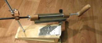
Assembling a jointing machine based on a jigsaw
A jointer is designed to remove existing irregularities from the surface of wood. The work process consists of one-sided planing of lumber along a plane. You can also shoot at different bevel angles. Thanks to processing on this equipment, beams or boards become smooth.
The design of the jointing unit is simpler than that of its thicknesser counterpart. This allows you to assemble the installation yourself using available materials.
The procedure for making a jointer
To make a planer for processing small-sized workpieces, you will need an electric plane that can be fixed in a stationary position. The base of the created unit can be a fragment of plywood, MDF or chipboard. A piece measuring 50 by 35 cm is sufficient. The thickness of the sheet material used should be more than 2 cm.
Assemble the jointing tool by performing the steps in the following sequence:
- cut out the base for the machine from the existing sheet material;
- a stop for the workpiece is attached to it using self-tapping screws or screws at an angle strictly of ninety degrees (a square is used to set it);
- install ribs that will ensure rigidity of the stop;
- An electric plane is attached to the base using M8 bolts and nuts.
Before fixing the stop, a hole is cut out in it for the pipe and for cooling the electric motor of the tool.
If you need to plan large workpieces, then it is enough to increase the size of the unit being created. This will result in a design as in the photographs below.
In addition to the considered option from an electric planer, jointing equipment can be assembled in another design. The practical implementation of such designs depends on the materials and creativity available to the home craftsman. How to make homemade jointing units of other designs is shown in the following videos:
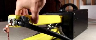
Making a stand for an electric planer
When working with an electric planer constantly, it is recommended to have a special stand that is suitable for storing it and installing the tool on it immediately after turning it off.
The need for a special stand is due to the fact that the metal drum with blades does not stop immediately after disconnecting the supply voltage from the instrument’s electric motor, but after a while (about 6 seconds). Throughout this period, he is still moving by inertia. The inertial duration of rotation itself depends on the massiveness of the drum and the power of the equipment used. At the same time, you cannot place a power tool with the sole on a table or workbench, because you can not only damage their surfaces, but also get injured.
To avoid holding the instrument in your hands the whole time the drum stops, you need to use a stand of a special design. The main element is a groove approximately 8 cm wide and 0.6 cm deep. It is necessary for the drum to rotate freely until it stops completely. The accuracy of the position of an electric plane placed on a stand (when the blades are above the cut groove) is ensured by the presence of a front stop made of a strip.
Required tools and materials
To make a stand yourself, you will need the following tools:
- an electric jigsaw equipped with a file for cutting out shapes;
- screwdriver with a set of bits;
- drill with metal drills 3 and 4 mm in diameter;
- awl;
- hand saw for wood with fine teeth;
- ruler or tape measure;
- square;
- pencil or marker;
- spherical wood cutter;
- sandpaper;
- chisel (enough with a 3-4 centimeter tip width).
To create the structure you will need the following materials:
- a piece of board up to 1 m long, 20 mm thick and 140 mm wide;
- wood screws – 2 pieces 4 by 45 mm;
- wooden plank 30 mm wide, 20 mm thick, and 140 mm long;
- 4 self-tapping screws with large heads 4 by 15 mm.
It is recommended to prepare all tools and materials in advance before making the stand, so as not to be distracted by small details during the work process.
Creation sequence
When making a stand for an electric plane, the following algorithm is used:
- Cut a fragment 50 cm long from the board with a saw or jigsaw.
- According to the diagram given above, mark the plank with the board.
- Drill holes for screws (according to the marks made at the required points) for fixing the stop.
- Try on the model of the electric plane being used to the prepared workpiece of the base of the stand, noting the future placement of the groove based on the location of the tool drum.
- According to the marking, a groove is cut out with a file, making it approximately 4 cm wider than this parameter for the slot for the drum. Notches are made along the edges and in the center.
- Use a chisel to remove wood from the groove and clean it.
- Use a jigsaw to saw off the excess from the workpiece.
- The front stop is secured with screws. 4 self-tapping screws are screwed along the edges, which will serve as the “legs” of the stand.
- The made stand is sanded with sandpaper to remove roughness.
Having finished the work, you should make sure that the groove is made of the required width and depth: to do this, simply place the power tool on top of the stand and look from the side at the location of the drum. If necessary, you will need to deepen or widen the groove.
After turning off (while the drum is still rotating), the instrument is placed in the following way:
- First, the front edge of the plane sole is supported;
- Only then lower the power tool onto the stand.
Making a stand does not require much time, labor or money. But this device makes the job easier.
Thicknessers and jointers made independently from an electric planer are much cheaper than their factory-made counterparts, but their functionality is inferior to branded equipment. However, they are quite sufficient to perform the basic operations for which these devices are intended. The practical use of homemade machines significantly speeds up wood processing, improves its accuracy and quality compared to the manual use of an electric planer.
Manufacturing stages
DIY workbench: manufacturing, drawings, models
The process of creating a jointing machine is carried out in several stages. Each is worth considering in more detail.
bed
First of all, the master should start assembling it. You can do it yourself if you take into account some points.
- The frame is usually made of a metal profile. The most common is a channel with a wall thickness of 6-8 mm.
- When creating a drawing of the frame, it is necessary to take into account that the load from the equipment and the workpiece is evenly distributed throughout the structure.
- During the assembly process, it is necessary to ensure that the elements are firmly fastened.
- Fixation of channels or other rolled metal elements is carried out by welding or threaded connections. If you need to manufacture a mobile machine, it is better to give preference to the second option.
Shaft with knives
To operate, a jointer requires a drum equipped with knives for processing wooden surfaces. It is with their help that it will be possible to remove a small layer of the workpiece to ensure smoothness. Features of shaft installation begin with its design.
The shaft is a separate mechanism, the design of which involves the use of blades and bearings. The shaft itself ensures the rotation of the blades. Assembling the structure of the unit will require taking into account some points.
- You won't be able to make blades yourself. Therefore, it is better to purchase suitable knives made of durable steel in advance. You can take blades from a router or grinder.
- The drum must be installed on the frame, securing it to bearings. They have special grooves.
- When attaching the mechanism with blades, you should carefully ensure that it fits firmly. It is this unit that bears the entire load during operation of the machine, and poor-quality installation will lead to damage to the device.
- At the end of the output shaft it is necessary to install a roller for fastening the rotation belt. When making a video with your own hands, it is recommended to take a responsible approach to choosing a profile. It is better to give preference to elements that fit the belt profile.
Table
Next in line is the table, which should be placed on opposite sides of the drum. The process of making a table is quite complex. This is explained by the need to achieve rigid fixation of the elements through the use of a special mechanism.
In addition, the surfaces of the countertops must be smooth.
Additionally, during installation you should monitor the level of the countertops. They should be flush with the drum
It is important that there is a possibility to adjust the height of the element. To achieve the desired result, it is recommended to install a special mechanism
The width and length of the table must correspond to the workpieces that are planned to be processed.
Engine
The rotation of the shaft with blades occurs due to the operation of an electric motor. The installation process of such a unit requires taking into account important points.
- First you need to choose the right electric motor. This can be done by first calculating the required power, which is enough to process the workpieces. For domestic use, electric motors with a power above 1 kW are a suitable option.
- The motor pulley should be positioned in the same plane as the drum pulley. During installation, it is recommended to use a level and measuring tools to achieve the required installation accuracy.
- Before mounting the engine, it is necessary to select pulleys, taking into account their diameters.
- The pulley belt should be well tensioned. Additionally, it is necessary to check the distance between the pulleys and bring it into compliance with established standards.
- It is worthwhile to provide a seat for the motor on the jointer in order to ensure possible adjustment of its position.
Emphasis
Another element, the installation of which requires taking into account some nuances. The stop is designed to hold the workpiece in the required position while it moves along the table. It must be secured at the far end of the table. You can use a strong piece of wood as a support.
A homemade jointer should be made as safe as possible. To achieve this, it is recommended to additionally manufacture a special protective casing that will prevent damage to the motor, rollers and belts during rotation of the blades.
To learn how to make a jointer with your own hands, see below.
Schematic diagram of the operation of a thickness planer
Why make a thickness planer with your own hands?
The scheme of work should be clear to most home craftsmen even without visualization, but for ease of understanding the tasks of making a surface planer yourself, it will not be superfluous.
There are two motivations for making any equipment yourself:
- desire for self-realization;
- desire for savings.
All the rest follow from those listed. And you can save a lot of things:
- first of all, money due to the abolition of auxiliary functions, which can be completely dispensed with in a home workshop;
- in the second - electricity by reducing the number of electric drives;
- thirdly, space in the workshop due to optimization and adjustment of dimensions.
If we talk about a full-fledged thickness planer, then, based on the three-dimensional drawing located below, its components can be reduced to the following list:
- electric drive from an electric motor with a power of 1.5 - 2.5 kW on a two-knife drum rotating at a speed of 5 - 10 thousand rpm;
- manual chain adjustment of the work table level;
- manual chain coupled feeding of the workpiece by two lingering pressure rollers.
But you yourself decide on the concept of your surface planer. Let's look at 3 approaches to implementing the idea of making your own thickness planer.
Necessary equipment
Homemade thicknesser
To make a surface planer from an electric planer with your own hands, you need to have:
- an electric planer, which it wouldn’t be a shame to convert into another tool;
- drawings of future equipment;
- plywood and blocks for assembling the equipment body;
- a small amount of free time.
First of all, when processing an electric planer, it is necessary to determine exactly what size parts will be created on the new machine. The dimensions of the thicknesser being created will directly depend on their dimensions: this equipment must have a body of the same width and height, as well as the length of the pin and guides, which will exactly match the workpiece.
General concepts
A thickness planer is a special machine for smoothly leveling a wood surface.
This equipment performs a planing action called thicknessing. It was in honor of this action that the machine got its name. In turn, before planing the wood plane, it must be perfectly flat. This result is achieved using a jointer, which aligns the horizontal line on the tree. However, this work is considered rough.
Purpose
Thickness equipment has its purpose in many industries where wood is used. With its help, various shields, bars, and boards are processed. An ideal result is achieved in all planes of the product.
For example, if you take a wooden beam, then at the end of the planing operations it will be very smooth on all four sides. Thicknessers, in particular industrial ones, have the property of processing large areas and the number of boards that have a large width.
Homemade surface planers weigh quite little. This ensures their trouble-free transportation. On homemade machines it is much easier to regulate the thickness of the chips removed during processing.
Type of equipment
Thicknessing equipment is distinguished according to the following criteria, namely the number of knives on the cutting shaft:
Unilateral.
Thicknesser one-sided
This machine is the simplest and has only one knife on the main shaft.
Also, a single-sided thicknessing machine is considered a budget option and is intended for home work.
Due to one knife, it is capable of processing only one side of the product.
Double sided
Thicknesser double-sided
This equipment has in its design two shafts with knives located parallel to each other.
This module is considered more productive.
Has an automated supply of wood blanks.
Professional thickness planer
Thicknesser special
Such machines have in their design from three shafts with knives or more.
This thicknesser is intended for professional wood processing, and also has the ability to produce parts in large volumes..
The price category of this equipment ranges from 35 thousand to 100 thousand rubles. However, if the machines are created with the latest technology, then the price, accordingly, will be quite high. Therefore, it will be easiest and also cheaper to create your own project.
Advice: If your budget allows you to buy a factory installation, then you need to choose the best one. However, if the budget is tight, then try to create an analogue. This will save you time and money.
In addition to the knife differences, surface planers also differ in scope of application
Budget - household
With their help, it is possible to achieve good performance. It has an affordable price range and small dimensions. By purchasing this machine, you can easily build your own house.
Combined
Limited by small volume of work and low price. It is intended primarily for domestic purposes. For many household purposes, this equipment is quite sufficient.
Semi-professional
They are widely used in carpentry workshops. Such equipment is capable of producing impressive volumes of finished products.
Professional thickness planers
Due to the fact that such equipment is more powerful than its smaller counterparts, it is capable of producing huge volumes of furniture blanks and components. They are used in woodworking factories.
Industrial modules
They are used only in sawmills, enterprises involved in the extraction and processing of wood. Such machines have huge dimensions and power, so using them in everyday life would be impractical.
Safe work on a homemade machine
Having converted such a hand-held power tool into a surface planer with your own hands, you should also remember about safety while using it. To make work on your new home machine as efficient as possible and completely eliminate the possibility of getting any injuries, you should adhere to the following rules when performing certain work:
- When processing any part, it is necessary to use eye protection;
- When working with rough material, gloves should be used;
- When starting work on a homemade machine, you should check the functionality and reliable fixation of all its parts;
- the pins and knives of the machine must not have any cracks or any other defects;
- Only clean workpieces that do not contain nails or any other metal particles can be processed on a homemade machine.
What is a jointer and jointer
Now, in the age of technology, if you type the word “jointer” into a search, you will see all kinds of jointing machines. However, originally a jointer was a hand tool designed for leveling wooden surfaces. It is an elongated plane with a double blade. When processing a wooden product with this tool, you should monitor the chips. When it becomes continuous, then you can understand that the work of leveling is nearing completion.
Such an instrument can still be purchased today. If you have a small amount of work and a lot of time, a simple hand jointer will be enough for you.
A jointing machine is most often a fairly large device with a lower knife shaft to which two or four knives are attached. In other words, the surface to be leveled should be located below. When the shaft rotates, irregularities are carefully cut off with knives.
How to properly adjust the tool being manufactured?
Adjusting the plane allows you to obtain a product with the required parameters. Among the features we note:
- The required power is set.
- Attention is paid to the degree of protrusion of the knives.
- The appropriate position of the tool is established.
Only after correct adjustment of the tool can you obtain a product with the required parameters. In addition, it is necessary to provide for the possibility of replacing the main elements in case of severe wear.
An electric planer is a useful device that is useful for planing wood, chamfering, cutting quarters and other tasks. Modern models significantly increase the speed of work and are convenient to use. But sometimes it’s not possible to purchase an electric planer in a store. In such a situation, you can try to create it yourself. Before starting work, they study all the details and stock up on the necessary equipment and parts.
Design elements
DIY drawing of a thickness planer from an electric planer
To assemble a surface planer from an electric planer, you will need a set of materials and tools necessary for the future machine.
If you need a thicknesser in order to generate income from products that you will process on the machine, then the best solution would be to purchase a ready-made device. If the thicknesser is a purely household tool for home work, then you can safely make it yourself.
The main components for assembling the unit are:
- Electric planer. Please note that each time you will not be able to re-equip the surface planer into a regular electric planer and reassemble the machine from it. Therefore, it is better to make a unit from a planer, which is not a pity;
- Blueprints. You can draw up your own drawing, based on the characteristics and features of the electric planer, the planned work and the parts that the machine must process. It is more difficult to adapt ready-made drawings for yourself, since each of them is based on certain models of electric planer, materials used, parameters, etc.;
- Wooden blocks and plywood. From these you will assemble the body of the future thickness planer;
- Free time. To make a machine with your own hands, you won’t need much time. But you shouldn’t try to assemble the unit in a couple of hours, otherwise the result may disappoint you.
The main emphasis when designing a surface planer based on an electric plane is on matching the characteristics and capabilities of the machine with the workpieces being processed. Before starting assembly, make sure that the equipment receives a body, studs, and guides that perfectly match the parts you will be dealing with.
Studs and guides
Photo of a drawing of a thickness planer made from an electric planer with your own hands
These components of a surface planer based on an electric planer should be discussed separately, since they play a significant role in the performance and efficiency of the surface planer.
- The pins allow you to lower and raise the thicknesser when processing workpieces.
- Often, beginners install the pin exactly in the middle of the machine body. But this decision is wrong. If you decide to make a machine, the pin should be installed in the middle between the front and rear handles of the device. This arrangement will ensure convenient work with the equipment and will allow you to securely fix the tool in the desired position. There will be significantly fewer problems during operation.
- When converting an electric planer into a surface planer, try to give the tool pin maximum mobility. To do this, install a rolling bearing on the top cover yourself.
- Attach a nut to the middle plate of the machine, which will be responsible for adjusting the height. This solution will provide you with the ability to adjust the position of the equipment in small increments and with increased accuracy. This is relevant for particularly delicate processing using a surface planer.
- Guides are used for precise and efficient processing of workpieces. They are made from wooden blocks, so the cost of assembling the equipment can be considered minimal.
- When making guides for an electric planer, make a certain margin in length. It is not recommended to make them identical in length to the processed workpieces. Do these elements a little more.
- The lower plane of the thicknesser from an electric planer is made so that when processing the product it moves immediately parallel to the cutters of the device. If the plane starts under the power tool, you will not be able to achieve high precision machining. Therefore, the effectiveness of such a machine will be reduced to a minimum.