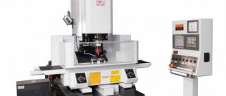
The site presents products of the Japanese company Okamoto: from small-sized machines for semiconductor manufacturing to gantry equipment. You will find detailed information in the catalog of metal grinding machines, the price and quality of which will pleasantly surprise you. The equipment has high accuracy and performance, maintaining precision parameters. The presented range meets the requirements of machine-building enterprises of small-scale and mass production. By purchasing equipment from Pumori-Engineering Invest, you receive a range of related services: engineering, commissioning, operator training, service. Don't know which model to choose? Send a request from the website - we will select equipment based on your needs.
Purpose, classification, cutting modes of grinding and finishing machines
Grinding machines of modern models are designed for the production of parts with small deviations in shape, size, low surface roughness and are characterized by high productivity.
Cutting processing performed by a plurality of abrasive grains is called abrasive processing.
Grinding is the cutting of metals with abrasive wheels. When grinding, the main cutting movement is the rotation of the tool, and the feed movement S (it can be longitudinal or plunging) is communicated to the workpiece or tool. A distinction is made between grinding with the periphery of the wheel and the end of the wheel. In the first case, the cutting part is the outer surface of the circle, the generatrix of which is parallel to the axis of its rotation, and in the second, the end of the circle.
Depending on the location and shape of the workpiece surface being processed, grinding is divided into the following types: external - the outer surface of the workpiece is processed; internal - the internal surface of the workpiece is processed; flat - a flat surface is processed; profile - a surface is processed, the generatrix of which is a curve or broken line.
Grinding a rotating surface is called cylindrical grinding, a spherical surface is called spheroid grinding, the side surfaces of gear teeth are called gear grinding, the sides and cavities of a thread profile are called thread grinding, and spline surfaces are called spline grinding.
A distinction is also made between grinding in centers (if the workpiece is mounted in centers) and in a chuck (if the workpiece is mounted in a chuck). In mechanical engineering, cylindrical (external and internal) and flat grinding are most often used.
Basic cutting parameters when grinding: speed of rotational or translational movement of the workpiece vз, m/min; grinding depth t, mm - the layer of metal removed by the periphery or end of the wheel as a result of transverse feed for each stroke or double stroke for cylindrical or flat grinding and radial feed Sp for plunge-cut grinding; longitudinal feed S - movement of the grinding wheel in the direction of its axis in millimeters per revolution of the workpiece for cylindrical grinding or in millimeters for each table stroke for flat grinding with the periphery of the wheel (Table 1).
Table 1. Cutting parameters for various types of grinding, sharpening and finishing
| Processed material | Characteristics of the grinding process | Workpiece speed, m/min | Grinding depth, mm |
| Cylindrical external grinding | |||
| Structural metals and tool steels | With longitudinal feed for each stroke: preliminary | 12…25 | 0,01…0,025 |
| final | 15…55 | 0,005…0,015 | |
| With longitudinal feed for double stroke | 20…30 | 0,015…0,05 | |
| Mortise: pre | 30…50 | — | |
| final | 20…40 | ||
| Hard alloys | With longitudinal feed: preliminary | 10…20 | 0,0075…0,01 |
| final | 20…30 | ||
| Cylindrical internal grinding | |||
| Structural metals and tool steels | On general purpose machines: preliminary | 20…40 | 0,005…0,02 |
| final | 0,0025…0,01 | ||
| On semi-automatic machines: preliminary | 50…150 | 0,0025…0,005 | |
| final | 0,0015…0,0025 | ||
| Hard alloys | On semi-automatic machines: preliminary | 20…30 | 0,005…0,01 |
| final | 25…50 | 0,005…0,0075 | |
| Cylindrical centerless grinding | |||
| Structural metals and tool steels | For preliminary passage: at d 20 mm | 20…120 | 0,02…0,05 |
| at d > 20 mm | 0,05…0,2 | ||
| final | 40…120 | 0,0025…0,01 | |
| Mortise: preliminary | 10…45 | — | |
| final | 10…30 | ||
| Surface grinding with wheel periphery | |||
| Structural metals and tool steels | On machines with a round table: preliminary | 20…60 | 0,005…0,015 |
| final | 40…60 | 0,005…0,01 | |
| On machines with a rectangular table in serial production: preliminary | 8…30 | 0,015…0,04 | |
| final | 15…20 | 0,005…0,015 | |
| On machines with a rectangular tool table: preliminary | 3…8 | 0,05…0,15 | |
| final | 0,01…0,015 | ||
| Hard alloys | Same machines: preliminary | 4…5 | 0,03…0,04 |
| final | 2…3 | 0,01…0,02 | |
| Flat grinding with a wheel end | |||
| Structural metals and tool steels | On machines with a rectangular table: preliminary | 4…12 | 0,015…0,04 |
| final | 2…3 | 0,005…0,01 | |
| On machines with a round table with vertical feed for each revolution of the table: preliminary | 10…40 | 0,015…0,03 | |
| final | 0,05 | ||
| On machines with a round table of single-pass grinding with automatic feeding of workpieces: preliminary | 2…3 | 0,1…0,15 | |
| final | 0,005 | ||
To calculate power for cylindrical grinding, if the longitudinal feed value is given in m/min, calculate the radial feed (mm/rev) of the workpiece using the formula Sр = S d/(1000Vз), where d is the diameter of the workpiece.
The wheel speed vcr for external, internal and flat grinding of parts made of structural metals and tool steel is 30...35 m/s, of hard alloys - 20...30 m/s, and when sharpening and finishing parts made of tool steel - 15...32 m /With.
Effective power , kW, when grinding the periphery of a wheel with longitudinal feed
(1)
for plunge-cut grinding with the periphery of a wheel
(2)
when grinding with the end of a wheel
(3)
where d is the grinding diameter, mm; b — grinding width, mm, equal to the length of the grinded section of the workpiece during cylindrical plunge-cut grinding and the transverse dimension of the workpiece surface when grinding with the end of a wheel.
The values of the coefficient CN and exponents in the formulas are given in [7].
ON REQUEST:
— Engine power can be increased up to 7.5 kW. Russians love high power and, due to relatively inexpensive electricity, try to buy more powerful woodworking machines. — Each grinding unit of the FINAL machine can have an electric motor with an inverter (frequency converter). This makes it possible to be more flexible in choosing the grinding mode. It is especially necessary to smoothly select the grinding speed of surfaces after priming, painting, varnishing, hard exotic woods, plastics, composite boards, and metal. An important point: FINAL flap grinding machines are equipped with an inverter (frequency conversion), and not a variator (mechanical device), which is an undoubted advantage of the Czech HOUFEK machines. — Stepless change in the feed speed of workpieces replaces two discrete feed speeds. A very necessary option, aimed specifically at precise selection of relative grinding speeds. — CNC machine – touch screen panel with graphical interface. The Czech company HOUFEK does not offer cheap programmers (like most Italian manufacturers of calibrating and grinding machines), we have full computer control, a multilingual menu (including in Russian), comprehensive fault diagnosis, etc. — FINAL brush-grinding machines have the ability to independently adjust one or more grinding units relative to each other. The operation is performed from the control panel without stopping the machine. This is the only way to achieve maximum convenience in selecting fine grinding modes - Vertical brush units can be installed in front of the feed belt conveyor. The units are adjustable to the desired width of the workpiece (manually or automatically), each has its own drive and guides. Act as edge grinding units. — Automatic centering of the feeding conveyor – a service function. The operator does not need to pay attention to whether the conveyor belt has gone left or right: everything is monitored by the sensor. The conveyor self-centers and the likelihood of damage is reduced to zero. — The double-sided extension of the work table on the FINAL brush-grinding machine is stationary. Calibrating rollers usually have a table or roller table in front, and extensions allow you to increase the base of the machine. Sometimes it is simply necessary. — A vacuum table and a powerful pump for it are necessary when sanding small-area workpieces or for finishing/intermediate sanding on primer and varnish. — Various packaging options for HOUFEK machines are useful when shipping by rail or road. You can order either the lathing of the machine or packaging in a solid wooden box. And as standard, all our machines are packed in shrink film.
Cylindrical grinding machines
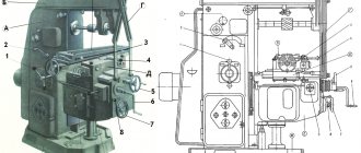
For longitudinal and plunge grinding of external cylindrical, flat conical and end surfaces with the installation of workpieces in centers or a chuck, cylindrical center grinding machines (Fig. 1).
Technical characteristics of the machine mod. 3M151F2
| Maximum size of the installed workpiece, mm: | |
| diameter | 200 |
| length | 700 |
| Workpiece rotation frequencies, s–1 | 0,83…8,33 |
| Grinding wheel speed, m/s, no more | 50 |
| Working feeds of the grinding head, mm/min: | |
| for pre-treatment | 0,2…0,12 |
| final | 0,1…0,6 |
| finishing | 0,02…0,12 |
| Speed, m/min: | |
| quick approach of the grinding head | 1,7…0,93 |
| table movement, m/min (number of steps 10) | 0,05…5 |
| Overall dimensions, mm | 4950x2400x2170 |
Rice. 1. Cylindrical grinding centering machine model 3M151F2 : 1 - electrical cabinet; 2 - front headstock; 3, 11, 13 — handles; 4 - steady rest; 5 — mechanism for automatic wheel editing; 6, 17 — flywheel; 7 — grinding head; 8 — cross feed mechanism; 9 — control panel; 10 - hydraulic station; 12 - tailstock; 14 — hydraulic control panel; 15 - pedal; 16 - axis; 18, 19 - upper and lower tables, respectively; 20 - bed
The machine is equipped with a specialized CNC device. UE input is performed using decade switches. In the control program, dimensions are specified in absolute values. The number of programmable coordinates is 2. The work is performed sequentially for each coordinate. The machine is equipped with two measuring devices and corresponding correction systems: to determine the deviation of the dimensions of the workpiece and the circle. Monitoring of the diametric wear of the circle (X coordinate) is performed and corrected when measuring the workpiece during processing with an active control device. Control of the base end of the workpiece (Z coordinate) is carried out with an axial orientation device.
The highly sought-after universal semi-automatic cylindrical grinding machine of particularly high precision mod. 3U12AF11 is designed for grinding external and internal cylindrical, conical and end surfaces when installing parts in centers, a jaw chuck, on a faceplate or collets in small-scale and mass production.
| Technical characteristics of a universal semi-automatic cylindrical grinder, especially high precision mod. 3U12AF11 | |
| Largest diameter of the installed product, mm | 200 |
| Maximum weight of the installed product, kg | 20 |
| Maximum length of the installed product, mm: | |
| external grinding | 450 |
| internal grinding | 75 at dot = 50 mm |
| Total power of installed electric motors, kW | 10,29 |
| Overall dimensions, mm, no more: | |
| without remote equipment | 2260x780x1680 |
| with remote equipment | 3600x2260x2040 |
| Weight, kg: without remote equipment | 3500 |
| with remote equipment | 4400 |
Cylindrical grinding machines are in great demand, the technical characteristics of which are given in table. 2.
Table 2. Technical characteristics of cylindrical grinding machines
| Model | Processing diameter, mm | Workpiece length, mm | Drive power, kW | Dimensions (L W H), mm | Weight, kg |
| KSh-3 SNC with CNC | 200 | 400 | 10,0 | 2300x1760x1603 | 1850 |
| VSH-152VI | 200 | 1000 | 9,0/11,0 | 2950x2295x2150 | 6000 |
The EJ 30 CNC external grinding machine has been designed to meet the current level of grinding technology. Practical experience in cylindrical grinding, the latest design principles and modern CNC technology have been precisely applied to the specific requirements that specialists place on grinding machines.
The layout of the machines suits any grinding task in single or serial production. This is illustrated by the following data.
Technical data of machine model EJ30
| Center height, mm | 150 |
| Diameter of the workpiece, mm | 290 |
| Clamp length, mm | 800 |
| Grinding length, mm | 800 |
| Weight of workpiece between centers, kg | 80 |
| Grinding spindle assembly | |
| Grinding wheel diameter, mm: max | 400 |
| min | 290 |
| Grinding wheel width, mm | 63 |
| Drive power, kW | 7,5 |
| Peripheral speed, m/s | 45 |
| Grinding wheel location. | Left |
| Machine characteristics | |
| Abrasive | Corundum |
| Cross feed | X-axis, CNC type |
| Longitudinal movement | Z axis, CNC type |
| Positioning accuracy of the cross feed axis, mm | 0,0001 |
| Machine weight, kg | About 7000 |
| Dimensions without cooling system (W D H), mm | 3,550×2,850×2,100 |
Note. Maximum values indicated.
Types of processing performed using grinding machines
Modern grinding machines are capable of performing a fairly wide range of various operations, and they are used to achieve different purposes. As a rule, the following types of processing of external and internal surfaces are performed on grinding machines:
- Rough peeling of rough blanks.
- Adjusting the surface roughness to the required value.
- Finishing the dimensions of the part to exact dimensions.
- Polishing of products with cylindrical, conical and flat surfaces.
- Tool sharpening.
Surface grinding machines
Surface grinding is often used instead of fine planing, fine milling and scraping. Flat surfaces can be ground with the periphery and end of the wheel (Fig. 2). A type of surface grinding is profile grinding, performed on surface grinding machines (see Fig. 2, g). When working with the periphery of a circle on machines with a rectangular table, the allowance is removed in the following ways.
When transverse grinding with working strokes, the transverse feed of the wheel (part) along the spindle axis is carried out for each table stroke; the wheel removes a layer of material with a thickness equal to the cutting depth, and a width equal to the transverse feed of the wheel in one table stroke. After the working stroke along the entire grinding surface, the wheel is set to a certain depth and the next layer is removed. The working moves are repeated until the allowance is completely removed.
When deep-feed grinding, the wheel removes the bulk of the allowance for each table stroke. After each table stroke, the circle (table) moves along the spindle axis at a distance H = 3/4...4/5 mm. The remaining part of the allowance (0.01...0.02 mm) is removed using the previous method.
When grinding with a stepped wheel, the main part of the allowance is distributed between the individual steps of the wheel and is removed in one working stroke; the last step removes a small layer of material; then finish grinding is performed with transverse working strokes.
Rice. 2. Schemes for surface treatment during flat grinding with the periphery and end of the grinding wheel : a, g - with a rectangular table; b - with a round table, the end of the grinding wheel; c - with a rectangular table; g - with a round table; d - with two vertical spindles and a round table; e - with two horizontally located spindles while simultaneously grinding two ends of the workpiece; 1 - blank; 2 — top line; 3 - bottom line
Based on the principle of operation, surface grinding machines are divided into machines for grinding the periphery and the end of the wheel; according to the shape of the table and the nature of its movement - to machines with reciprocating and rotary movement of the table; according to the degree of versatility - into universal, semi-automatic and automatic. Surface grinding machines with a rectangular table are produced with horizontal and vertical spindles; non-automated and semi-automatic machines - with active control devices.
In small-scale and medium-scale production, surface grinding machines with a rectangular table and a horizontal spindle are most often used. In mass production, the most widespread are machines with a round table, as well as double-sided face grinding machines with horizontal and vertical spindles (Tables 3 and 4).
Table 3. Technical characteristics of surface grinding machines
| Model | Workpiece dimensions, mm | Drive power, kW | Dimensions (L W H), mm | Weight, kg |
| ZD711AF10 | 230 450 | 2,2 | 1780x1480x1820 | 1735 |
| ZD711VF11 | 240 630 | 4,0 | 2595x1775x2030 | 2850 |
| OSH450 | 280 630 | 4,0 | 2340x1785x2030 | 2400 |
| ZL722V (A) | 320 1250 | 11,0 | 4810x2630x2030 | 7000 |
| LSH324 | 800 1600 | 11,0 | 5580x3480x3900 | 12 000 |
Table 4. Technical characteristics of profile grinding machines
| Model | Workpiece size, mm | Table movement, mm | Dimensions (L W H), mm | Weight, kg |
| 3951VF1U | 150 60 78 | 150 60 | 1955x1650x1960 | 2400 |
| 3952VF1U | 250x100x130 | 200 100 | 2035x1960x2035 | 3000 |
Surface grinding machine mod. 3E711VF3-1 is designed for grinding workpieces of various profiles using the plunge method, as well as flat surfaces using the periphery or end of the grinding wheel.
The transition from preliminary to finishing grinding is ensured by sensors. Machine accuracy class B. Accuracy of machined surface: deviation from plane 4 µm, parallelism 2 µm, roughness Ra = 0.16 µm. The machine is used in conditions of single and small-scale production.
Technical characteristics of the machine mod. 3E711VF3B1
Dimensions of the working surface of the table, mm. . . . . . . . . . . . . . . . . 400 200
Highest cutting speed, m/s. . . . . . . . . . . . . . . . .35
Speed, m/min:
longitudinal movement of the table. . . . . . . . . . . . . . . . . . . . 2…35
vertical movement of the grinding head
(stepless regulation) . . . . . . . . . . . . . . . . . . . . . . . . . . . 0.015…1.5
Automatic vertical feed, mm
stepped . . . . . . . . . . . . . . . . . . . . . . . . . . . . . . . . 0.002…0.01
in the range 0...0.01 mm. . . . . . . . . . . . . . . . . . . . . . . . . . After 0.002 mm
in the range 0...0.1 mm. . . . . . . . . . . . . . . . . . . . . . . . . . . After 0.02 mm
Automatic cross feed (stepless regulation),
m/min . . . . . . . . . . . . . . . . . . . . . . . . . . . . . . . . . . . . . . . 0.16…10.0
Overall dimensions of the machine, mm. . . . . . . . . . . . . . . . . . . . . . 303x2360x2080
Purpose
The scope of use of such high-tech machines is quite wide - they are used by both small businesses and large enterprises.
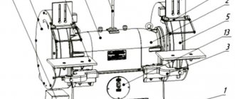
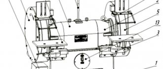
Polishing machines are quite a useful thing in the hands of a master and they are intended for final polishing of the surface of products up to roughness class 11-12. When working on a polishing and grinding machine, a very thin top layer is removed from the surface of the workpiece, thus finishing the material. At the heart of such an industrial machine is an abrasive wheel, which does all the polishing work on the workpiece.
Scheppach TiGer 2000S water cooled
A metal polishing machine is used to process surfaces made of stainless steel, brass, aluminum, etc. They can also be used to polish pipes, sheets of metal, various flat surfaces and extruded profiles, as well as finished parts.
Wood grinding and polishing machines are used in woodworking, furniture industry, and for the manufacture of decorative parts.
For stone processing, cantilever lever machines are used.
Such equipment can easily handle the processing of chairs and tables, polished mirror sheets, chests of drawers, and door handles. There are models that polish stone and a variety of ceramics.
Centerless grinding machines
In centerless grinding, the product is shaped when the workpiece comes into contact with the leading and grinding wheels and support knife 3 (Fig. 3). During processing, the workpiece 4, which has an initial error, gradually acquires a shape approaching the shape of a cylinder. This effect is enhanced by using a special knife, with a higher position of the workpiece above the line of the centers of the grinding and driving wheels, as well as with an increase in the rotation speed of the workpiece.
The workpiece rotates freely without fastening in the prism formed by the support knife 3 and the driving wheel of the headstock 2. This eliminates deformation of the part when it is clamped, and rotation in the prism allows you to effectively eliminate deviations from the roundness of the ground surface. For high-quality processing, it is necessary that the part begins to rotate until it touches the grinding wheel of the headstock 1, which is largely determined by the condition of the support knife. The knife must have a straight supporting surface of high hardness and roughness parameters
Rice. 3. Schematic diagrams of centerless cylindrical grinding machines : 1 - with a horizontal line of centers; a - with a stationary grinding head; b - with movable headstocks; 11 - with an inclined line of centers; c - with a fixed grinding head; d, e, f - with movable heads and a fixed support; III - with two leading circles; 1 - grinding wheel headstock; 2 - headstock of the leading circle; 3 — support knife; 4 - blank
Ra = 0.08...0.16 µm so that the coefficient of friction between the part and the knife is minimal. The most common centerless cylindrical grinding machines are semi-automatic mod. 3D180, 3M184I, 3M184 high precision, semi-automatic mod. 3M182A and 3M184A of especially high precision, as well as automatic machines mod. 3Sh182D, 3Sh184D (finishing), cylindrical grinders - 3F47V, 3A47V, centerless internal grinding machines 3F484GV, 3A485V.
Centerless grinding machines are in good demand, the technical characteristics of which are given in table. 5.
Table 5. Technical characteristics of centerless grinding machines
| Model | Grinding diameter, mm | Workpiece diameter, mm | Dimensions (L W H), mm | Weight, kg |
| ZE180V | 0,5…10 | 56 | 1570x1145x1755 | 1200 |
| ZE183AM (VVM) | 2…40 | 140 | 2940x2150x2120 | 4700 |
| ZE184AM (VM) | 4…80 | 245 | 3570x2355x2120 | 6990 |
| ZE185VM | 8…160 | 360 | 3840x2450x2120 | 9150 |
Internal grinding, sharpening and grinding machines
Holes in parts on internal grinding machines are processed by passing and plunging. The plunge method is used when processing short, shaped and blind holes that do not have grooves to exit the circle. In all other cases, pass grinding is used, which provides higher accuracy and a lower surface roughness parameter.
The domestic industry produces internal grinding machines of the following models: 3K225V; 3K225A; 3K227V; 3K227A; 3K228V; 3K228A; 3K229V; SSH162; SSH64.
For machine mod. 3K227A, the diameter of the grinding holes is 20...150 mm. The SSh162 machine is a special semi-automatic machine designed for high-speed grinding; SSh64 - centerless special. Machines mod. 3K225A; 3K227A and 3K228A - especially high accuracy.
As an example of the technological capabilities of the machines under consideration, the technical characteristics of the internal grinding machine mod. 3K228V:
| Largest diameter, mm: of the workpiece being installed | 560 |
| installed workpiece in the casing | 400 |
| Maximum length, mm: of the installed workpiece | 200 |
| at the largest grinding hole diameter | 200 |
| Diameter of grinding holes, mm | 50…200 |
| Maximum table stroke, mm | 630 |
| Maximum adjustment transverse movement, mm: grinding headstock: | |
| forward (from the worker) | 60 |
| back (to worker) | 10 |
| workpiece headstocks: | |
| forward (from the worker) | 200 |
| back (to worker) | 50 |
| Maximum angle of rotation of the workpiece, degrees | 30 |
| Maximum diameter and height of the grinding wheel, mm | 180 63 |
| Table movement speed, m/min when dressing the grinding wheel | 0,1…2 |
| when grinding | 1…7 |
| with fast longitudinal inflow and outflow | 10 |
| Spindle rotation speed, s–1: | |
| internal grinding | 75; 100; 150; 200 |
| blanks | 1,66…10 |
| face grinding device | 66,66 |
| Grinding wheel drive electric motor power, kW | 5,5 |
| Weight (with attachments), kg | 6900 |
Technical characteristics of grinding and grinding machines are given in table respectively. 6 and 7.
Table 6. Technical characteristics of grinding machines
| Model | Grinding wheel diameter, mm | Drive power, kW | Dimensions, (L W H), mm | Weight, kg |
| ZL631 | 200 | 0,75 | 610x372x362 | 66 |
| TS-2 | 300 | 2,2 | 610x470x1340 | 112 |
| ZK634 (ZT634) | 400 | 4,0 | 1000x680x1400 | 385 |
| VZ-379-01 | 350 | 2,8 | 1000x700x1400 | 210 |
Table 7. Technical characteristics of sharpening machines
| Model | Product size, mm | Working area, mm | Drive power, kW | Dimensions (L W H), mm | Weight, kg | |||
| VZ-318 universal | Diameter 250, length 500 | Length 225 | 0,71 | 1185 | 1195 | 1630 | 1020 | |
| VZ-31BE universal | Diameter 250, length 500 | Length 225 | 0,85 | 1185 | 1195 | 1630 | 1020 | |
| ZV622 diamond sharpening tool for cutters | Height 6…25, length 35…300 | Table 210 400 | 1,6 | 600 | 730 | 1400 | 550 | |
| ZE692 diamond sharpening for saws | Diameter 250…1430 | Plunge per cycle | 5 | 2,2 | 2450 | 1120 | 1910 | 1800 |
| ZE653 semi-automatic for sharpening drills, countersinks, taps | Diameter 5…32, length 50…400 | — | 2,0/1,5 | 1012 | 1310 | 1595 | 950 | |
| VZ-531F4 grinding and sharpening (CNC center) | Diameter 250, length 400 (in centers) | — | 3,0 | 2500 | 3500 | 2350 | 5500 | |
