Milling parts at home
When deciding on the type of machine, you need to start from the work that can be performed with its help.
You can mill:
- Surfaces of parts, achieving the desired planes.
- Create grooves into which keys will subsequently be installed, for example, for mounting pulleys or gears on shafts.
- Cut teeth on gears or sprockets; these parts are used in car transmissions or gearboxes.
- To give an original shape to cast or forged products, milling is carried out using special programs or models (originals).
- Saw recesses for the passage of liquids or gases in special devices.
- To produce original medals, tokens, badges and other exclusive small-sized products.
Modern innovations in individual production
In the home workshop, modern craftsmen, commissioned for large enterprises, process parts according to the attached drawings. Such part-time work is also beneficial for enterprises: there is no need to use additional technological equipment in the workshop to perform routine operations.
The home craftsman carries out work under a contract with the customer; he solves problems of delivery of blanks and parts independently. As a result, the overhead costs of the main production are reduced. The workplace is created by the contractor himself.
To organize the production of income, it is enough to create an individual enterprise (IE) in order to have official status (financial calculations are simplified). Currently, there are enough such organizations; they carry out significant volumes of orders.
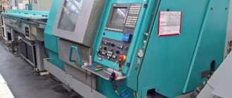
Features of Numerical Control (CNC) Machine
For a home workshop, CNC equipment is often a waste of money. The fact is that machines of this type are powerful and bulky, despite the controls they are not so multifunctional, and are more often designed to perform a strictly defined range of work.
A distinctive feature of the device is that it is not controlled directly by the operator, but using electronic devices. Therefore, the machines are safer than standard ones, because the risk of hand injury is minimized. The differences are called:
- precise processing of parts;
- easier operation of the machine;
- removing the human factor;
- changing turns and tools automatically;
- selection of program type (positional, contour or combined).
CNC machines are options for large-scale mass production. The ability to record a program and strictly follow it allows you to obtain completely individual parts.
Basic Milling Tools
A metal milling machine is created for a specific type of cutter. Here the master has a solid choice:
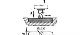
- A finger tool is used to form grooves. The width and depth of the future groove according to the specified parameters is carried out in one or several passes.
- Face mills can machine planes. Fastening is done using a shank with internal thread. Additional fixation is achieved using a Morse taper.
- Shape milling, as well as the production of teeth for mechanical gears, is carried out using special cutters. They may have a finger or disk appearance.
- To obtain spiral grooves, dividing heads are additionally used. Depending on the location of the table, a certain part of the cylindrical workpiece is processed. Each linear movement of a part is accompanied by its rotation through a given angle.
Selecting a working head for fixing the tool
Nobody can make an electric motor on their own. Ready-made electric motors are used. To transmit torque from the rotating shaft to the tool, you need to have a special coupling. It must have a conical hole for attaching the shank or have a collet chuck.
Drilling machine
Making such devices is quite difficult. It is much easier to take as a basis nodes that contain the necessary elements. Most often, fragments of tabletop drilling machines are used.
Drilling equipment has a separate shaft. It receives drive from an electric motor through a block of V-belt pulleys. It is relatively simple to regulate the rotation speed of the main shaft at constant engine speeds. You just need to move the belt from one stream to another. It simultaneously moves on the driven and drive shafts.
If such a decision is made, then all that remains is to modify the cartridge for fixing the tool. The regular three-jaw chuck can be left behind. However, it will need to be upgraded to include a threaded shank mount.
Attention! The tangential resistance to movement that arises during the milling process will necessarily tear the tool out of the chuck. With increasing feed (tool movement per revolution), the resistance increases in proportion to the square of the increase in the speed of longitudinal movement.
The drilling and milling machine will be able to perform work in two different modes. This is the path followed by most craftsmen who want to have complex technological equipment in their workshop.
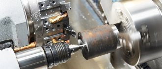
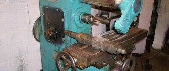
Milling lathe
Make a metal milling machine based on turning equipment. The presence of a convenient three-jaw chuck on a lathe allows you to secure conical fasteners for cutters in it. The part is fixed using clamps or a hand vice to the support on which the tool holder is installed. Power is usually measured in tens of kW, and the gearbox provides a significant number of options for main shaft rotation speeds.
In this version, the user will receive a turning and milling machine. The remodeling process will not take much time. Required.
- Remove the tool holder.
- Install the auxiliary plate.
- Attach clamps to the plate or use clamps.
- Install a cutter inside the chuck.
- Fix the part on the plate.
- Determine the milling progress.
- Bring the part to the tool and process it according to the specified parameters.
Using a hand router
Hand-held electric routers are available for processing wood and soft metals. They are suitable for processing hard materials. For this purpose, sufficiently powerful supports are designed that can withstand significant tangential (lateral) loads. It is necessary to ensure the rigidity of the structure of the unit itself.
Use steel angles or profile rectangular pipes with thick walls. They are used to weld racks for attaching the router (it has a spindle for attaching the shanks of the cutters).
Most routers have special platforms that can be mounted on a stand. Since the dimensions of the processed parts can differ noticeably from each other, the supports are made in the form of a console or portal.
For a home workshop, console structures cannot have a large reach in the horizontal plane. Only large floor-mounted machines allow the cutter to be positioned further away from the stand. Tabletop units have limitations.
Portal structures can have significant tool offset. But even here you should approach it wisely. Large parts are rarely processed on a milling machine. It is difficult to make such a machine at home.
Fixing the part and working movement
The presence of a mechanism for axial movement in the equipment allows you to set the movement of the tool to a given depth. Some craftsmen create universal equipment that can be used to process different types of materials.
The design task will be to develop a table. The workpiece to be processed must be secured to it. Mechanization should allow the upper part to be moved relative to the tool in two directions.
Therefore, the design includes fixed and moving parts. Most often they are connected to each other using wedge grooves. When moving under such conditions, the gap is selected to a minimum. Rigid relative fixation guarantees the quality of the work performed.
The movement of the moving parts occurs due to the lead screws. By rotating the handwheel, the milling machine forces the upper part of the table with the fixed part to move. The presence of two lead screws located at an angle of 90⁰ allows you to position the part relative to the cutter anywhere.
How to make a machine for metal?
How to make a wood milling machine with your own hands
When milling metal, high stress and vibration occur. The wooden frame will not support them. It is necessary to use a cast iron plate and a metal profile made of low carbon steel.
Option #1
The machine consists of:
- base;
- rack;
- slides with transverse movement guides;
- work table moving in the longitudinal direction;
- spindle head;
- stand with vertical guides;
- electric motor
https://youtube.com/watch?v=u2rbbCkZZnA
The cast iron base is leveled. A transverse dovetail groove is cut into it. A stand under the spindle carriage is attached to the rear part. The slide is inserted into a longitudinal groove. They move in the transverse direction due to the rotation of the screw. Ready made from a lathe will do. A table is installed on top. It moves along the figured slide guides. The tool moves vertically along with the carriage along the guides of the rack. A spindle head is installed on a massive plate in front, and a motor is mounted on the side. Both units are connected by a belt drive.
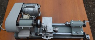
Option No. 2
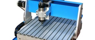
Using an electric drill as a milling head, you can create a simple and lightweight model of a vertical milling machine.
- Make a base in the form of a frame from a profile pipe.
- Place a slide with a screw on it for longitudinal movement.
- A tool holder from a lathe with a cross screw and a vice are installed on top.
- There are 2 stands attached to the base. They are connected by 3 cross members for rigidity. The bottom one is at the base. The top 2 serve as support for the spindle carriage.
The drill moves vertically along the carriage guides. A rectangular metal profile is used to manufacture the machine. All connections are made with bolts. Due to 2 racks, the design is stable and durable.
Design stages
Many craftsmen work only using sketches. The final adjustment of the location of the parts is made only when installing them on the frame. The necessary holes are drilled on site, and then installation is carried out. Quite often it is necessary to change the relative position of nodes. The drilled holes are welded. The time investment is quite large.
Modern computer technology puts a powerful tool in the hands of designers - three-dimensional modeling using engineering programs. The choice of software is large. It’s not difficult to master any of them; just install it on your computer and watch the lessons published on the Internet.
- To make virtual editing easier, three-dimensional models of solid bodies are created. Existing parts and assemblies are measured.
- Using computer program tools, analogues with exact dimensions (within a reasonable tolerance) are developed.
- The scene is designed - the location of the future placement of the machine in the workshop is modeled.
- The frame and components are placed on the virtual stage.
- You can move elements around the model, achieving a rational installation in height, width and space of the scene.
- Some components can be designed locally, in relation to the existing model.
- Once the modeling is completed, working drawings are created. This procedure takes a little time. It is enough to transfer the projections of assembly units and parts onto coordinate planes and arrange the dimensions.
- If necessary, to better understand the design features, cuts and sections are made. They help to understand the interactions between individual parts and their structure.
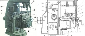
Design and principle of operation of the equipment
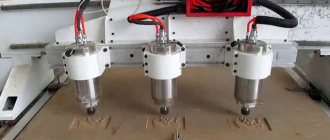
If you look at the drawing of a professional milling group machine, you will notice that its design includes many different mechanisms and components. A desktop home machine, unlike a serial one, has a simpler design, consisting of a limited set of required elements. Despite the simplicity of the system, a homemade milling group machine is a fairly functional device and allows you to successfully solve many problems related to the processing of metal and wood workpieces.
Step-by-step making of a simple do-it-yourself milling machine
Tool
Before starting production, you need to select the necessary components. They will be used during the work process. Tool you will need:
- A welding machine will help produce a welded frame for future equipment.
- An electric drill and a drilling machine with a set of drills will allow you to make the necessary mounting holes.
- A set of keys and screwdrivers is necessary for connecting parts and assemblies when assembling the structure.
- Painting with a spray gun will give the product an industrial look.
Stages of machine manufacturing
A coordinate vise will be installed on the machine's work table. Their peculiarity is that the fixed part can move in the desired direction.
To guarantee milling in different directions, a rotary support is provided in the underframe. It can be oriented at any angle, and then secured in the selected position.
An electric mixer will be used as an electric motor. Power is 1300 W. There is a bushing to attach the chuck and finger cutter to the threads.
The mixer can rotate at different shaft speeds. A built-in regulator is used.
The presence of a special platform allows you to mount the tool on a stand.
Refinement is being carried out: a special roller with M10 thread is machined.
The cutter shanks will be fixed in a three-jaw chuck. It was decided to use a cartridge with a maximum diameter of 16 mm.
For most standard sizes of cutters, this diameter is sufficient.
The frame has been made. It uses a channel and a plate heating radiator. For ease of use, the overall length of the radiator is cut in half.
Welding seams are reinforced with gussets. During welding, a special jig was used, which ensured that the welded workpieces were perpendicular to each other.
The frame is painted with an alkyd-based primer. Alkyd enamel is applied on top.
Channel No. 18 was used. Markings were made for the upper faceplate. Holes were drilled to install the mixer faceplate on the vertical stand of the frame.
At the bottom of the rack you can see holes for attaching the lower support. The base for the cylindrical rotating support will be attached to them.
The total height of the rack is 980 mm. During the design, the conditions for milling possible parts were simulated. After analyzing three-dimensional models, the optimal dimensions of the rack were determined.
Holes are visible on the bottom support. They will install a tubular support and a bearing housing for the drive mechanism for vertical movement of the desktop.
The width of the lower support is 550 mm, the depth of the support measures 500 mm. The stand will provide space for installing such a support.
Measuring the depth of the reference plane.
View from below. Bolts are welded at the corners. Rubber shoes will be attached to them. With their help, vibration of the machine will be eliminated.
There are roller chain tensioners; their role will be described when installing the chain drive in the mechanism for vertical movement of the table.
Rubber shoes are attached to threads. An M10 nut is secured inside the shoe using vulcanization.
The length of the bolt is chosen to be 60% of the height of the rubber shoe. The elastic support will be securely held on the base of the bed.
Elements of tubular supports are shown. One is inserted into the other. The cylinder with flange is designed to be mounted on top of the table plate.
The lower support has a pipe with a flange welded perpendicularly. It is necessary for additional fastening of the support base to the vertical post. This design provides additional rigidity to the entire machine structure.
There is a support inside the tubular support. A lead screw is installed to it. As it rotates, the inner tube will move.
Instead of a flange, a sprocket is welded on; a chain can be installed on it. A chain drive will be organized. With its help, the inner tube with the table can move vertically up and down.
Installing the support on the lower plane. Additional fixation of it to the vertical stand of the frame.
An additional retainer is visible. It is necessary for subsequent fixation of the tubular lift in a certain position.
The tubular work table lift is now installed. There is a flange on top. It will be needed to install the table plate.
Another view. There is a hole visible on the bottom support. It is necessary to install the mechanism for controlling the vertical movement of the table.
The work table is a plate that will be attached to the flange on the pipe. A coordinate vise will be placed above.
The process of installing a plate on a tubular lifting element.
It is shown how the coordinate vise will be installed. The travel drive flywheel is located outside the plate; when it rotates, longitudinal horizontal movement will be ensured.
The vice will hold the workpiece, preventing it from moving.
Now you need to think about how to control the height of the table. The bearing housing is installed. A shaft will pass through it, and a flywheel will be installed on top.
This roller will go through the bearing. At one end there is a keyway for attaching the flywheel, at the other there is a welded chain sprocket.
By rotating the handwheel, you can control the vertical position of the desktop. An ebonite flywheel was found. It will be pleasant for your hands to touch its surface when working on the machine.
The handwheel itself is installed on top of the base plate. It will be easy to use while operating the equipment.
The chain is connected from below. The small star controls the big one. Therefore, the small one is the leader, and the big one is the follower.
Now you can see how the chain tensioners work. They maintain the required tension, which prevents the chain from falling down.
Now it's time to install the milling head. The modified mixer is placed on a vertical stand.
The mixer faceplate is attached to holes drilled in the stand. An additional frame is made; it helps to place the working head in a position perpendicular to the work table.
For visual control of the table position, a micrometer head is installed. It will help the operator set the desired depth of metal processing.
The machine is placed on a special stand. It can be seen that the desktop does not rise much above the surface of the workbench. When operating, the milling operator does not need to raise his arms high. The dimensions of the equipment are selected correctly.
Having secured the corner in a coordinate vice, you can mill a groove on it. A finger cutter with a diameter of 8 mm is used.
Similar operations are often performed on shafts. Subsequently, gears or pulleys are installed on them. The operation is in demand for gearboxes.
Surface milling with an end mill. Such operations are needed to give parts flat surfaces. Most often, such an operation is needed when processing aluminum or cast iron castings.
If necessary, you can install a simple mechanical drive to rotate the flywheel of the coordinate vise. It is often equipped with a simple CNC. Then the work will be partially automated. The miller will only have to install and remove parts on the table.
Video: DIY metal milling machine.
Milling table assembly process
You should start assembling a homemade machine for your home by making a work table - the most important structural part of the milling equipment. You can make your own desktop for a home machine from a sheet of plywood, plexiglass or sheet metal.
Supplies you'll need are high-quality contact adhesive, double-sided tape, and plenty of sandpaper. In addition, you will need to purchase several clamps, hardware and a high-quality copy router, which must have maximum accuracy and have a sharp cutting surface. The technical capabilities of your desktop machine will largely depend on how high-quality the milling cutter you purchase.
Drawing of a milling machine made like a milling table (click to enlarge)
To make your own milling equipment, use the following instructions.
- The first step in assembling a homemade machine is making the lid. Plywood can be used as a material for it. The simple process of manufacturing this element is as follows: blanks of certain sizes are cut out of plywood, then they are connected to each other.
- The next stage of assembling a home mini-machine is the installation of fasteners, installation of a router and other structural parts. Since you are engaged in the manufacture of milling equipment, all work should be performed with increased accuracy and precision.
- After assembling the desktop, you need to install a mounting plate on it. For this purpose, a recess is made in the surface of the desktop, the contours of which completely follow the shape of the mounting plate. The mounting plate is fixed in this recess using double-sided tape. Next, gaskets are laid along the entire contour of the plate with a certain step, which are pressed against it using clamps.
- The working part of the machine itself—the copy milling cutter—is installed in bearing units, the assembly of which should be given special attention.
- All technological holes required on the surface of the work table can be obtained using a conventional hand drill.
- Your mini table saw will have a number of wood surfaces that need to be thoroughly sanded using sandpaper.
- The next stage in the manufacture of a homemade machine is the assembly of the base, which must be carried out in strict accordance with the previously prepared drawing.
- When assembling the machine, special attention should be paid to the process of installing the stop and the pressure comb.
General view and kinematic diagram of the milling table
All the structural elements of homemade milling equipment, which were mentioned above, have a great influence on the performance, accuracy and reliability of the machine, so the issues of their manufacture and installation should be approached very responsibly and carefully.
In order for your DIY milling machine to be reliable, durable, accurate and look presentable, you need to perform a number of final procedures for its assembly.
- All wooden surfaces of the machine should not only be thoroughly sanded, but also treated with a special oil impregnation, which will protect them from the negative effects of the external environment.
- The controls of the milling machine, as well as all the switches necessary for its full operation, must be placed in an accessible and convenient place.
- An important part of the machine is a special pipe to which a vacuum cleaner hose is connected, which is responsible for removing small chips from the processing area.
When making a home milling machine, you must act in strict accordance with the drawing and assembly algorithm. If these conditions are met, as well as the accuracy and precision of assembly work, you can count on the fact that your mini-equipment will delight you with its functionality, performance, accuracy and reliability for a long time.
A home milling machine is an indispensable equipment for processing metal and other materials with your own hands. If you set a goal, you can build a mini-copy of industrial equipment, significantly saving on components, and the machine can additionally be equipped with turning functions. A homemade metal milling machine is quite easy to make; during the manufacturing process, you just need to be patient and have on hand detailed drawings typical of serial equipment.