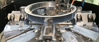
Purpose of the 3M636 grinding machine
The 3M636 roughing and grinding machine is produced by a Russian machine-building enterprise and is designed to remove the defective layer of material from workpieces on castings, forgings, rolling, stamping and welding workpieces.
In this case, the surfaces of the workpieces are cleaned without shaping them. In terms of accuracy class, the 3M636 roughing and grinding machine complies with the “H” standard, which means that the equipment is excellent for finishing work. This machine is equipped with two 600mm grinding wheels with a width of 75mm, which are driven by a powerful 11kW power motor. The rotation speed of grinding wheels ranges from 955-1425 rpm. In this case, the distance between the centers of the circles is 1025 millimeters.
The 3M636 peeling machine is capable of processing fairly large products. The maximum weight of the workpiece reaches 30 kg, which is enough to perform most of the tasks encountered in a foundry. The unit is equipped with a workbench (worktable) measuring 240x380 mm.
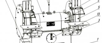
Layout of the main parts of the 3M636 machine
b) - rear view (casing 8 not shown)
List of main parts of the 3M636 roughing machine
- Frame
- Bearing shell
- Brackets for hand rests
- Protective cover
- Grinding wheel
- Lighting lamp
- Helpers
- Protective cover with handles
- Outlet pipe
- Motor mounting plate
- Drive pulley
- Shaft
- Control Panel
- Electrical cabinet
- Brackets for protective screens
- Transparent protective screens
Description of the design of the 3M636 sharpening and grinding machine
On the upper part of the machine body 1 there are bearing housings 2 and a protective casing 8 with handles. The bearings support the shaft 12 on which the drive pulley 11 is mounted. The pulley 11 has the ability to move axially along the drive shaft 12 of the machine. Rotation of the pulley 11 is transmitted by V-belts from an electric motor located inside the housing 1 and fixed to the plate 10. Auxiliary installation movements of the electric motor are made along the horizontal grooves of the plate 10. The belt tension can be adjusted using the vertical grooves of the plate 10. Protective covers 4 are attached to the bearing housings 2 with outlet pipes 9. Inside the casings 4, grinding wheels 5 are fixed on the shaft 12. The brackets 3 are supports for the tool rests, which can be installed at the height required by the operator. The presence of grooves in the hand rests 7 allows you to move them to the desired position.
Protective transparent screens 16 are installed on the brackets 15. The machine operates only with the protective screens 16 lowered.
For stripping (cleaning) cast iron and steel castings, medium-hard (ST2) and hard (T) wheels with a grain size of 20 and 24 units are used. The permissible rotation speed of the wheel when cleaning castings is determined by the peripheral speed in the range of 40-50 m/sec.
The 3M636 machine is intended for operation in UHL climatic conditions for placement category 4 according to GOST 15150. The ambient air temperature in working conditions must be at least 5°C, relative humidity 45÷80%. Illumination of the workplace is not lower than 200 lux. Atmospheric pressure 630÷800 mm Hg. Art.. The time of day is not regulated.
Standard device structure
The 3M636 grinding machine has several main components that work harmoniously with each other. The design of a roughing and grinding machine is not complicated.
Head with two-speed electric motor. Thanks to it, the movement of abrasive wheels is ensured. The shaft is housed in a housing with two covers. Its ends are equipped with bearing units, which simultaneously support the spindle.
Spindle supports - the presented unit ensures the reliability of the equipment and the accuracy of rotation of the wheels. The supports contain seals.
Cooling unit - the operation of the electric motor is accompanied by the release of a large amount of heat, which can lead to breakdown. Therefore, the device must be cooled during operation. This is accomplished due to air flows located in the cavity of the housing and inside the frame. They circulate constantly, they have no obstacles.
Head covers - protective covers are attached to them. Additionally, it is allowed to fix devices for polishing workpieces on them.
Grinding machine head covers
Bed - most often it is made of cast iron. Inside the frame there is a cabinet in which all electrical equipment is hidden. In the front part there is a window that gives access to all internal components of the equipment. During operation, it is securely closed with a lid.
Transparent protective screens. They protect against metal dust and make work more convenient. A lamp is adopted as an additional device.
Replacing the grinding wheels is quick, because to do this you just need to fold back the side of the casing.
The design of the device is quite simple, so some craftsmen are able to build the device themselves. However, in the household there is no need for a stationary option, since at home you will not have to process hundreds of workpieces every day.
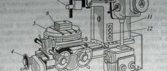
3K12 Arrangement of components of the grinding machine
List of components of the 3K12 grinding machine
- bed 3К12.10.000
- throttle block 3K12.77.000
- hydropanel 3K12.73.000
- feed type selection valve 3K12.74.000
- table 3К12.20.000
- product headstock 3K12.50,000
- installation of automatic switch 3K12.84.000
- pneumatic visual reading device BZ-6060V
- alarm panel 3K12.83.000
- internal grinding spindle ZB12-44-00
- device for internal grinding 3K12.45.000
- grinding head 3K12.40.000
- tailstock 3K12.51.000
- hydraulic panel for hydraulic drive station 3K12.78.000
- electrical cabinet panel 3K12.85.000
- product drive 3K12.88.000
- electrical cabinet 3K12.81.000
- air preparation unit 3K12.15.000
- upper slide 3K12.41.000
- fencing 3К12.21.000
- table hydraulic cylinder 3K12.110.000
- lower slide 3K12.42.000
- installation of feed screw 3K12.61.000
- cooling supply unit 3K12.12.000
- quick approach mechanism 3K12.43.000
- automatic condensate drain valve 3K12.79.000
- hydraulic drive station 3K12.71.000
- pressure gauge valve 3M2.1-C320
- control handle 3K12.75.000
- control panel 3K12.82.000
- spindle lubrication installation 3K12.13.000
- hydraulic system 3K12.70.000
- feed mechanism 3К12.60.000
- manual table movement mechanism 3K12.30.000
- cooling supply pipeline 3K12.14.000
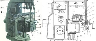
Kinematic diagram of surface grinding machine 3B722
Kinematic diagram of surface grinding machine 3B722
Vertical feed chain of the grinding headstock
Manual feed. The movement from flywheel 35 is transmitted through gears 23, 22, clutch 21, bevel gear pair 20, 19 to nut 18 connected to lead screw IX..
Since the nut is fixed against vertical movement, when it rotates, screw IX will move in the axial direction and move the carriage with the grinding headstock.
Automatic feeding. At the moment of reversing the grinding head, oil is supplied to one or another cavity of the cylinder of the feed mechanism 46 and moves the plunger rack 47. The latter, through the gear 48, rotates the crank 45, which, through the connecting rod 44, turns the lever 43 with the pawl 37 sitting on it at an angle of 40-50° .
The pawl turns the ratchet 25 connected to the flywheel 35. The movement is then transmitted along the chain described above to the screw.
The amount of automatic feed is adjusted by turning the cover 24, as a result of which the pawl 37 can turn the ratchet 25 along the entire path of its movement or part of it. The position of the cover 24 is changed from the handle 30 through gears 28, 27, 29, 26 and a gear sector cut on the cover 24.
To automatically stop the feed after removing the set allowance, a sector 31, 88 mounted on the limb 36 is used. At the same time, it enters the rolling zone of the pawl 37, which begins to slide along it without touching the teeth of the ratchet 25.
When working manually, a hard stop 38 is brought to the “hard stop” by the handle 39, against which at the end of the stroke the stop mounted on the dial 32 rests. The dial is connected to the flywheel 35 by means of a gear lock 33, which is activated by pressing the button 34.
Accelerated movement. An accelerated installation movement is prepared by turning the handle 41. In this case, using a helical groove on the shaft using a lever 49, gear 22 is disengaged from gear 23 and flywheel 35 is disconnected from the feed chain. At the same time, the cam 40 presses the limit switch 42, which unlocks the push-button station for starting the electric motor of the rapid movement mechanism.
When the electric motor is turned on, the movement from the electric motor shaft is transmitted by a silent chain through sprockets 52, 53. Gears 50, 51 to screw IX along the previously discussed chain.
In this case, the grinding head moves up or down.
Grinding headstock cross feed chain
Manual feed. From flywheel 12 through a worm gear (worm 5 - gear 4), rotation is transmitted to rack and pinion gear 2, which is meshed with rack I mounted on the grinding headstock.
To prevent the transmission from breaking when the grinding head is hydraulically moved from the cylinder, worm 5 is disengaged from gear 4 by turning handle II. In this case, the eccentric sleeve is blocked by cam 6 and lever 3, excluding the movement of the grinding head from the hydraulic cylinder when the worm is turned on.
Automatic feeding. When the grinding headstock moves transversely from the hydraulic cylinder, pin 17, mounted on the headstock body, slides along the spiral groove of shaft III, causing it to rotate. Next, through gears 16 and 15, a disk with adjustable stops 13 is driven into rotation. The disk with stops makes almost a full revolution at the maximum transverse passage of the grinding headstock, and the stops, acting on the reversible handle 14, rotate it together with the roller and the lever 9 sitting on it. The lever with one of its fingers acts (when reversing the grinding headstock) alternately on the limit switches 7 and 10, which give the command for vertical automatic feed, and with the other finger it switches lever 8, connected to the reversing spool of the grinding headstock reverse hydraulic box.
Handle 14 can also be used to manually reverse the grinding headstock.
Grinding head drive. The grinding wheel spindle receives rotational motion through a coupling from a flange-mounted electric motor with a power of 10 kW at 1460 rpm.
Setting up the machine when sharpening cutters
Sharpening cutters on back surfaces
When sharpening cutters along the rear surfaces, it is necessary to loosen the screw securing the support in the curved guides and set the rear angle along the dial, tighten the screw securing the support (Fig. 14. a).
Set the protractor at an angle of 90° - φ (φ is the main angle in the plan) or φ1 (auxiliary angle in the plan) (Fig. 14, b, c, d) and secure the protractor so that the middle of the sharpened edge coincides with the middle of the diamond ring circle. It is necessary to ensure that the length of the section where the cutter rests on the protractor bar is as long as possible. After this, the assistant is given a rocking motion (oscillation). The amount of oscillation is set by the stops of the oscillating tool rest.
The cutter should not be allowed to come off the diamond ring of the grinding wheel.
The set of accessories includes devices for sharpening the back surfaces with a cutter clamp and a protractor without a clamping device. When working without a clamp, the cutter is fed to the wheel by moving the cutter along the support bar of the protractor; when working with a clamp, the flywheel is rotated. It should be borne in mind that at angles φ and 90° - φ less than 45°, it is better to use a device with a cutter clamp.
Sharpening cutters along the radius
The radius is sharpened manually, and oscillation of the table is not required.
When sharpening straight cutters along the front surface, the work is carried out in a device for sharpening the rear surfaces with a mechanical clamp (Fig. 14, e), but the cutter must be laid on the table with the side plane of the holder and the base of the holder pressed against the reference ruler of the dial.
The required front angle of the cutter is set using the protractor, and the inclination angle is determined using the tilt dial of the tool rest.
Sharpening is done by oscillating the tool rest, and feeding is done by rotating the cross-feed handwheel.
Sharpening bent cutters along the front surface
When a device for sharpening the front surfaces is installed on the tool rest, it is an inclined tool rest (Fig. 14, e).
The device is fixed at an angle. A device for sharpening the rear surfaces is secured in the groove of the tool rest, aligning the “0” of the protractor with the edge of the groove. The rest of the settings and work are carried out in the same way as when sharpening straight cutters on the front surface. The creation of thresholds on the front surface of the cutter is similar. The circle for this purpose must be profiled according to the shape of the transition part of the sill.
Finishing of cutters
The finishing of the cutters is carried out with a finishing diamond wheel in the same way as sharpening. Recommended modes when working with coolant - transverse feed for 10 double strokes of the table, mm:
- pre-sharpening: 0.1..0.2
- finishing sharpening: 0.03..0.06
- finishing: 0.01..0.02
Longitudinal feed is independent, carried out by springs within the range of 1..4 m/min.
When feeding manually, there should be a cutter pressure on the wheel of 7..12 kgf/cm2 (when sharpening a cutter with a sharpening strip of 10 x 2 mm, the pressing force is 2..2.5 kgf).
Cooling
Grinding, sharpening and finishing with diamond wheels should be done with cooling.
The use of coolant during the grinding process increases the durability of diamond wheels and reduces the wear rate of diamond grains.
The coolant reduces the heating temperature of the workpiece (tool) and reduces local stresses that can lead to cracks and chips. In addition, the coolant removes grinding waste from the working surface of the wheel, which helps to significantly reduce the “greasing” of the wheel surface, increase the cleanliness of the machined surface by one or two classes, increase productivity by 25..30% and reduce the wear rate of the wheel by up to 50%.
When using metal-bonded wheels, cooling is mandatory (except for shaped finishing) and must be continuous. Coolant should be supplied in an amount of 2 - 3 l/min. Organic bonded wheels can be used without cooling,
Coolant splash protection
The protective casing of diamond wheels is made with a reversible flap, and a disk is placed in the circle to prevent intense splashing of coolant.
It is necessary to ensure that the damper, when working with cooling, completely covers the non-working area of the grinding wheel.
To protect against the jet of coolant knocked off by the cutter, there is one shield with a permanent magnet on each side of the machine, mounted on the tool rest or on the cutter holder. In addition, shields installed on the edge of the trough prevent splashes from hitting the floor of a working machine and provide protection for the worker.
Grinding and grinding machine 3M636
On the market you can find a variety of offers of grinding equipment. But the 3M636 machine is the most common.
Double-sided sharpening machine 3M636
3M636 is designed for cleaning and roughening parts in industrial environments. Its excellent performance has resulted in high market demand. It is called a standard that confirms reliability.
In terms of class accuracy, this equipment is classified as standard “H”, and this becomes evidence that the described technique is used for the final finishing option. This machine was equipped with a pair of 60-centimeter grinding discs with a width of 7.5 cm. They are driven by a seven-kilowatt powerful motor. Grinding discs of version 3M636 rotate at speeds from 950 -1420 rpm. The distance between their centers is 102.5 cm.
3M636 machines can process fairly large castings. The maximum weight of a part can be 30 kg. This is quite enough to complete all the tasks that need to be solved in foundry production.
Unit features
The bed is made of cast iron. All important elements are located inside the part. Access is provided through a special window in the front part, which is closed with a special lid.
To fix the wheels on the spindle, adapter flanges with three crackers on the outside are used, which help with balancing.
The instruction manual prohibits operating the machine without protective covers made of steel.
The casing is equipped with two visors made of organic glass. To collect dust that is generated during the processing process, retractable dampers and dust collectors connected to the hood are used. This helps reduce dust accumulation by up to 40% during roughing and grinding work.
Transparent screens with protective functions are equipped with lighting using a lamp. The passport recommends using 41.6 W lamps in this case.
To change the circles, no additional effort is required; you just need to fold back the side of the metal protection.
The set of the grinding and grinding machine model 3K634 includes:
- turntable;
- handyman
These elements allow sharpening of turning cutters up to 100 mm high. During operation of the 3K634, strong vibration occurs, which requires specialists to be fully aware of the load-bearing capacity and strength of the floor covering. Before installation, a proper installation plan must be developed.
3B632 Main dimensions and mounting locations of the sharpening and grinding machine
Main dimensions of the 3B632 sharpening and grinding machine
Fastening the ABC diamond cup wheel on the 3B632 machine
Fastening the A5P diamond wheel on the 3B632 machine
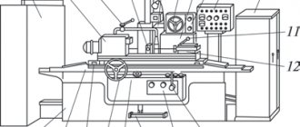
Location of controls for the 3M151 grinding machine
Location of controls for grinding machine 3m151
Control panel for grinding machine 3m151
List of controls for the 3M151 grinding machine
- Input circuit breaker
- Handle for turning on the automatic feed of the grinding head
- Dial for setting allowance for finishing grinding
- Dial for setting the total amount of allowance for grinding
- Coolant release handle
- Lamp switch
- Hard stop activation handle
- Manual cross feed handwheel
- Cross feed dial clamp screw
- Rough feed speed control knob
- Finish feed speed control handle
- Remote Control
- Tailstock quill clamp handle
- Handle for manual retraction of the tailstock quill
- Tailstock quill tension adjustment handle
- Hydropanel
- Tailstock quill hydraulic release pedal
- Flywheel for manual table movement
- Upper table rotation screw
- Signal lamp "Network on"
- Signal lamp "Lack of lubrication" of the spindle bearings of the grinding headstock
- Signal light "Forced feed"
- Signal light "Rough feed"
- Signal light "Finish feed"
- Signal light "Nursing"
- Checking the serviceability of signal lamps
- Product speed indicator
- Grinding wheel drive motor load indicator
- Machine operation cycle switch (adjustment - semi-automatic)
- Switch to start and stop rotation of the product
- Grinding method switch (longitudinal, plunge grinding)
- Manual cross feed clutch switch (on/off)
- Grinding type switch (with active control device - all the way)
- Feed rate adjustment switch (feed off, boost feed, roughing feed, finishing feed, feed off)
- Periodic feed switch (feed every table move, left feed, right feed)
- Switch for the number of nursing strokes
- Product rotation speed regulator for rough grinding
- Regulator of product rotation speed during finishing grinding
- Starting the grinding wheel
- Starting rotation of the product
- Turning off product rotation
- Moving the grinding head forward
- Moving the grinding head back
- General stop
- Starting the hydraulic pump
- Push micron feed
- Regulator of the time relay for curing during plunge-cut grinding
- Table reverse lever
- Throttle for regulating the speed of hydraulic movement of the table during rough grinding
- Handle for quick approach (tilt the handle toward you), retract (tilt the handle away from you) of the grinding headstock, start moving the table from the hydraulic drive when grinding (towards you and to the right) and dressing the wheel (towards you and to the left), moving the table to the right (away from you and to the left) to the right) and to the left (away from you and to the left) with the grinding head retracted
- Throttle for regulating the speed of hydraulic movement of the table during finishing grinding
- Throttle for regulating the speed of hydraulic movement of the table when straightening
- Table reverse delay control throttle on the left
- Table reverse delay control throttle on the right
Roughing and grinding machines
The main function of a traditional roughing and grinding machine lies in its name. The intended purpose of such machines is the same, but despite this, they are divided into the following types:
Further details about them:
- Stationary. This category is represented by single- and double-sided peeling units, which are used for finishing small parts. This type of grinding equipment is divided into radial grinding and facing subtypes. The first type is very popular. This is facilitated by its characteristics, among which it is necessary to highlight multifunctionality. The set of such a grinding machine included abrasive wheels with a diameter from 40 to 75 cm. Their grinding intensity varies from 4 to 50 m/s.
- Hanging. This type of roughing and grinding machine is used for finishing medium and large-sized castings. The distinctive characteristics of this machine are that it is suspended. This allows you to unfold a large structure, raise and lower it without much physical effort. A distinctive feature in this case is the high power of the built-in electrical units and the large size of the abrasive ring. Accordingly, the performance indicator of this configuration is quite large.
- Special. This grinding-grinding branch is used by automatic and semi-automatic machines. It should be noted that they are used in the mass production of parts.
In a special roughing and grinding machine, a significant number of actions are performed automatically. A person is only required to install a “rough” version of the workpiece and then remove it after processing.
Device classification
There are different designs of grinding machines on the market. There are three main groups of devices.
Stationary - such units are used for processing small workpieces.
The stationary grinding machine is
But grinding on the market is available one-sided and two-sided. This group includes a radial sharpening device - it is more popular because it performs many functions, a trimming device. Stationary equipment is equipped with grinding wheels, the diameter of which ranges from 40–75 cm.
Suspended units - with its help medium and large workpieces are processed. The device does not stand on the floor, but is suspended. It is more convenient, since it can be turned in any direction; such manipulation makes the grinding of parts better. In addition, working with a suspended device is physically easier. It is equipped with a larger abrasive wheel and also has higher power.
Special – these include semi-automatic and automatic units. More often they are used in mass production of blanks. Fully automated devices can do without direct human intervention. They are more productive, you just need to set the appropriate settings.
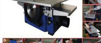
Today, the industry produces mobile machines that are more convenient to use and help increase productivity.
Mobile grinding machine
But the better the casting of the part, the less effort will be required to polish it.
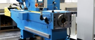
Hanging machine
The overhead roughing and grinding machine is used for processing medium and large sized metal castings. A special feature of these machines is that they are suspended, which makes it possible to rotate the massive structure in a vertical plane around its axis, as well as lift and lower it without applying significant effort.
Suspended machines are distinguished by the high power of built-in electrical units, as well as the large dimensions of the abrasive wheel. Of course, with such a “set” the labor productivity of the master is quite high.
General layout of internal grinding machines 3K227A and 3K225A
The machines consist of components indicated in general views and listed in the list.
The layout of the machines is visible from general views showing the location of the main components.
Both machines 3K227A and 3K225A are widely unified. A number of nodes are exactly the same or have minor differences. These include a cross-feed mechanism, a face grinding device, a straightening apparatus, and an end stop.
The machine bed serves as the basis for installing and fastening the main components of the machine. In the upper plane of the frames, longitudinal steel hardened guides are installed: V-shaped and flat, and there is also a bath for collecting and draining the coolant. The hydraulic control equipment is located in the front niche of the frames. The niche is closed with a lid, on the front side of which the machine controls are located.
The table makes a reciprocating movement from a hydraulic cylinder. Adjustment movement of the table is carried out manually from the flywheel for manual movement of the table, located on the front side of the frame. Reversing the table during grinding and straightening is carried out by stops fixed on the front side and acting on the reverse hydraulic panel.
The bridge is installed to the left from the upper plane of the frame (see Fig. 7, 8, 9). In the machine mod. The 3K227A bridge has transverse sliding guides along which, with the help of a screw, the slide carrying the headstock of the product can move during adjustment. In the machine mod. The ZK225A bridge has transverse rolling guides, on which the slide carrying the headstock of the product moves with the help of a ball pair from the transverse feed mechanism.
The headstock of the product (see Fig. 10) by means of a worm pair, sprocket and chain can be rotated on the plane of the slide at an angle of up to 45°, which makes it possible to grind conical holes. The front spindle support is a double row roller bearing with a tapered bore. The rear support is based on double preloaded bearings. The through hole of the product spindle is used for the coolant pipeline or for the rod of the product clamping mechanism when using special chucks. The spindle drive of the product with stepless rotation speed control is carried out from a DC electric motor through a belt drive.
An end grinding device with an end grinding spindle (see Fig. 11, 12, 13, 14, 15) allows you to grind the outer end of a product from one setup with grinding of both cylindrical and conical holes.
The rotation of the bracket carrying the end spindle into the working and non-working position is carried out in the machine mod. 3K227A, hydraulically when turning the crane 37, in the machine mod. 3K227A - manually using handle 130. Feeding of the face grinding wheel for plunging is carried out manually by turning the handwheel 88.
The grinding headstock (see Fig. 16) is installed on the upper plane of the table, has transverse rolling guides along which slides move, carrying a stand with an internal grinding spindle, and an electric motor that rotates the grinding wheel through a flat belt drive.
In the machine mod. The 3K227A stand with a pneumatic spindle is installed directly on the machine table and has no lateral movement.
The air spindle power supply panel is installed on the right side of the frame.
The cross-feed mechanism (see Fig. 17), installed on the front of the grinding headstock in the machine mod. 3K227A on the front of the bridge in the machine mod. 3K227A, provides transverse movement of the grinding wheel in the machine mod. 3K227A and products in the machine mod. 3K225A.
The adjustment movement is carried out from the flywheel 29, the dosed feed is from the handle 27 and the mechanical intermittent feed for each double stroke of the table is from the cylinder 113.
The cross-feed mechanism has a device 32 for automatically turning off the feed and retracting the table to its original position after removing the set allowance amount.
The end stop, installed on the machine bed and table, is designed for longitudinal feed of the table for plunge-in when grinding the inner end of the product with the end of the internal grinding wheel. Fine longitudinal feed is carried out manually by turning the dial.
A coolant tank with an electric pump, a magnetic separator and a conveyor filter is installed to the left of the machine bed and is used to clean the coolant from sludge.
The hydraulic drive pumping station and electrical cabinet with electrical equipment are installed at the rear of the machine bed.
Devices for sharpening cutters and tools supplied with the machine
Oscillating tool rest
An oscillating hand rest with accessories (Fig. consists of a heat-treated steel plate mounted on a cast iron bracket. The bracket, in turn, is mounted in a cast iron guide along a cylindrical surface. Movement of the bracket in the guide allows rotation of the hand rest at an angle from - 10° to + 20°. The angle of rotation is measured on a scale.
Two leaf springs attached to the base are attached to the guide. The base rests on two cylindrical guides, pressed into a bracket that is attached to the machine bed.
Due to the springs, the tool rest oscillates on the order of 100..130 vibrations/min along the plane of the grinding wheel. The magnitude of the oscillation stroke is adjusted using stops.
The design provides for the movement of the tool rest along cylindrical guides using a screw pair, ensuring the feed of the cutter onto the wheel with an accuracy of 0.01 mm. To ensure the required sharpening angles of the cutters in plan, a protractor is attached to the table. The protractor can be moved along the grooves of the tool rest to sharpen various cutters. To protect the worker from splashes of coolant or a sharpened cutter, a magnetic shield is installed on the tool rest.
Device for sharpening the back surfaces of cutters
The device for sharpening the back surfaces (Fig. 9) is a protractor with a clamping device. The device is fixed in the groove of the tool rest. Using the protractor dial, the angle in terms of the cutter being sharpened is set. The cutter is clamped using a clamp and a special nut with a handle. The protractor is clamped with a standard nut regardless of the cutter clamp.
Device for sharpening the front surfaces of cutters
The device for sharpening the front surfaces (Fig. 10) is made in the form of a rigid inclined table with a constant angle of inclination equal to 45° or 60°, rotating around a vertical axis by a given value of the front angle (within ± 30°). Count the angle of rotation of the table using a protractor.
The tilt of the tool rest is changed by reinstalling the upper wedge plate with a 180° rotation.
The specified angle of inclination of the main cutting edge is set by rotating the tool rest around an axis parallel to the end of the circle.
The mechanical fastening of the cutters is made in the form of a pawl with a spring-loaded spherical stop of the installation rotary dial, which is set to “0” during operation. It is recommended to tighten the protractor with a nut.
The position of the cutter relative to the end of the circle is adjusted by moving the clamp along the groove on the inclined plane of the tool rest. The symmetrical position of the groove allows sharpening of both right and left incisors.
3B632 diagram for setting up a device for applying chip breaking holes on a grinding machine
Diagram for setting up a device for applying chip-breaking holes
Tool supplied with the machine
The cost of the machine includes a puller for removing the flange with grinding wheels from the machine spindle.
Mandrel for dressing diamond wheels . Dressing must be done by grinding the diamond ring on cylindrical grinding machines. Moreover, diamond wheels should be adjusted only in cases of: “salting” of the wheel; uneven wear of the diamond ring, leading to blockages of the cutting edges of the sharpened tool: the need to restore the shape of the profile wheel.
The axial runout of the working surface of the diamond ring of a wheel on the machine spindle should not exceed 0.02 mm for ABC wheels.
For balancing wheels, the machine kit includes a balancing mandrel .
Power supply system for electrical equipment of the 3G71M machine
The machine is connected to a three-phase alternating current network with a voltage of ~380 V, a frequency of 50 Hz.
- Asynchronous squirrel-cage electric motors M1-M3, M5, M6, M8 and transformer TP3 are supplied with a voltage of 380 V alternating three-phase current.
- The electric motor M7 is supplied with a voltage of ~220 V alternating three-phase current, taken from the transformer Tr3.
- The control circuit and electromagnet EM1 are supplied with a voltage of ~110 V AC from transformer Tr2.
- The local lighting bracket LI is supplied with ~24 V AC voltage from transformer Tr2.
- The signaling equipment L2 and L3 is supplied with a voltage of ~5 V AC from the transformer Tpl.
- The electromagnetic device is supplied with 110 V DC voltage through the rectifier D11. The DC control circuits operate from the voltage taken from the D10 rectifier, the input of which is supplied with a 36 V AC voltage from the Tpl transformer.
- The contactless limit switch VB2 is powered by a constant voltage taken from the rectifier D26, the input of which is supplied with a voltage of 31 V from the windings of the 36 V and 5 V transformer Tpl, connected in opposite directions.
Technical characteristics of roughing and grinding machines
In terms of accuracy class, the 3M636 type roughing and grinding machine, which has proven itself in Russia and the post-Soviet countries, meets the “H” standard, which means that the equipment is excellent for finishing work. This machine is equipped with two 600mm grinding wheels with a width of 75mm, which are driven by a powerful 7kW power motor. The rotation speed of grinding wheels ranges from 955-1425 rpm. In this case, the distance between the centers of the circles is 1025 millimeters.
The 3M636 type roughing and grinding machine is capable of processing fairly large products. The maximum workpiece weight reaches 30 kg, which is enough to perform most tasks encountered in a foundry. The device is equipped with a small work table 110x200 mi
Technical characteristics of the grinding machine for sharpening cutters 3B633
Technical characteristics of the grinding and grinding machine 3B633
Related Links. Additional Information
The main function of a traditional grinding machine is clear from the name. But, despite the general purpose, all such equipment is divided into three main categories: stationary machines, suspended units and special-purpose machines. To study this technique in detail, it makes sense to consider each of the areas in more detail.
Information about the manufacturer of the surface grinding machine 3B722
The manufacturer of the 3B722 surface grinding machine is the Lipetsk Machine Tool Plant, founded in 1929.
In 1956, the tractor repair plant was reoriented to produce machine tools and renamed the Lipetsk Machine Tool Plant.
Machines model 3B722 B are typical representatives of the range of surface grinding machines with a rectangular table of medium size and allow processing flat surfaces of a wide variety of parts with micron precision. When using additional devices, these machines can also process shaped surfaces.
Machine tools produced by the Lipetsk Machine Tool Plant, LSZ
- 3B722
- surface grinding machine with a horizontal spindle 320 x 1000 - 3D722
- surface grinding machine with a horizontal spindle 320 x 1000 - 3L722V, 3L722A
- surface grinding machine with a horizontal spindle 320 x 1000 - 3P722
- surface grinding machine with a horizontal spindle 320 x 1000; 320 x 1250; 320 x 1600