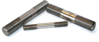
What are foundation bolts-anchors
Structures of this kind are primarily intended for industrial purposes and are intended for fixing metal structures - machine tools, machines and other industrial equipment - to concrete. In essence, they act as mortgages. And this article will tell you in detail about the dimensions, length, weight of foundation bolts (anchors).
This video will tell you what a foundation anchor is:
Product structure
Fundamentally, the design of a foundation bolt is no different from a conventional anchor:
- a notched pin – inserted into the wall of a structure or used as a fastening element for a mechanism;
- anchor part - extension, embedded in a concrete base;
- the upper part of the anchor can vary greatly in shape and is determined by its purpose.
The principle of fastening, which ensures the retention of the structure, also fully corresponds to the concept of an anchor - an anchor. Three forces can act:
- friction - the fastener absorbs the load from the structure and transfers it to the monolithic base due to the friction forces that arise during expansion. Which, in fact, determines the obligatory presence of an expanding part;
- stop - the load perceived by the fastener and compensated by the resistance of the material itself;
- gluing is a load compensated by stress at the point of contact between the base material and the anchor. This factor operates in chemical foundation anchors and in cases where the structural form does not provide for support.
The design and dimensional parameters of foundation bolts-anchors are regulated by GOST 24379.1-80 and GOST 24379.0-80.
Since the fastener is designed to secure heavy structures in very dense materials, its strength must be outstanding. Typically, high-quality or high-quality carbon steel, as well as low-alloy steel, are used for this. It is possible to make anchors from stainless steel, but, as a rule, such products are made to order. Only galvanized fasteners may be used.
Advantages and disadvantages
Products of this kind are highly specialized. In their field, foundation bolts have no competition, but they are not used in other fields.
The advantages of anchors include:
- very high load-bearing capacity;
- wide variety of designs. The methods of fastening equipment are different, so products are produced with a wide range of design differences;
- There are 2 installation methods available. This allows the use of bolts both during construction and at later stages;
- large size range - depending on the purpose, products with lengths from 15 cm to 5 m are produced;
- Despite the fact that high-quality steel is used for manufacturing, the cost of the products is relatively affordable.
Disadvantages of the product:
- the foundation anchor is not universal. Its scope is limited to the installation of structures on a concrete base;
- its use requires certain knowledge, since accurate calculations are important here, taking into account the foundation material, design features, installation method and much more.
The following describes the types of foundation bolts.
The use of such hardware
The area of use of the foundation anchor is determined by its qualities: high load-bearing capacity and durability. Application is limited to the base material.
Fasteners can only be installed in heavy, dense materials:
- concrete – heavy and especially heavy;
- natural stone;
- solid brick; fastening into hollow brick is prohibited.
Despite the specificity, many works are carried out using anchors, both large industrial and household ones:
- first of all, this is the installation of industrial equipment: machine tools, machines, pressing and electrical equipment, and so on;
- when repairing foundations, new fragments are bolted to old ones;
- when installing a beam grillage - in this case, the anchor is fixed in the pile, and the tie-rods are attached to it. This method, in addition to reliability, also ensures the absence of cold bridges;
- anchors mount the base during installation in order to use them as fasteners for the facing material. This option is more reliable than laying hooks under the cladding;
- In everyday life, a foundation bolt is most often used when attaching large-scale attachments. The anchor is stronger and more durable than self-tapping screws and dowels.
Popular product brands
Many companies are engaged in the production of foundation bolts. These products are quite simple to manufacture and are quite in demand. The most famous foreign companies include Simpson Strong-Tie, Hillman Group, USP. In Russia, Neva Resources is also the largest.
- The cost of products depends on the size, the quality of the steel, and the design.
- A straight carbon steel foundation bolt will cost 70 rubles. per kg. The same stainless steel fasteners cost from 613 rubles. per kg.
- A bolt with a conical end costs from 320 rubles. per kg. But just a flat anchor plate for a bolt will cost 3,202 rubles. per piece
- A composite foundation bolt costs from 355 to 5750 rubles. per piece
A foundation anchor is a special type of fastener designed to fix heavy structures to dense material. It is indispensable when fastening equipment, for example, or building structures, but is practically not used in other areas.
Foundation washer enlarged
- Material: 40x, St3, St20, St35, St45, 09G2S, etc.
- Coating: uncoated, galvanized, with thermal diffusion coating
- Diameter: M12, M16, M20, M24, M30, M36, M42, M48, M56, M64, M72, M80, M90, M100, M110, M125, M140
| Stud thread diameter, mm | Diameter of hole in washer, mm | Washer diameter, mm | Washer weight, kg | Price including VAT, rub. |
| M24 | 25 | 55 | 0,120 | 59 rub. |
| M30 | 32 | 80 | 0,330 | 117 rub. |
| M36 | 38 | 90 | 0,410 | 140 rub. |
| M42 | 44 | 95 | 0,610 | 208 rub. |
| M48 | 50 | 105 | 0,740 | 250 rub. |
| M56 | 60 | 115 | 0,950 | 339 rub. |
| M64 | 68 | 130 | 1,210 | 424 rub. |
| M72 | 76 | 140 | 1,530 | 565 rub. |
| M80 | 85 | 160 | 2,270 | 805 rub. |
| M90 | 95 | 180 | 2,880 | 1005 rub. |
| M100 | 105 | 190 | 3,400 | 1227 rub. |
| M110 | 115 | 200 | 3,630 | 1355 rub. |
| M125 | 130 | 240 | 6,300 | on request |
| M140 | 145 | 270 | 7,990 | on request |
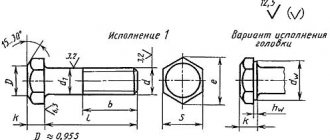
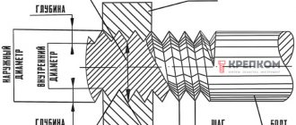
Bolt design features
When developing an anchor bolt with a nut GOST 24379.1−2012, specialists sought to create a fastener capable of withstanding heavy loads.
The most important element of such a system is the threaded rod. The load-bearing capacity of the anchor depends on it. The nut is screwed on from above, the lower part of the axle has the shape of a cone.
After the stud, a special bushing is considered an important part of the design ; its side surface has longitudinal slots resembling peculiar petals. The sleeve completely covers the stud. Only one upper part remains free, where the nut is located.
The work of the anchor structure is quite simple.
The device is placed in a pre-prepared hole. The nut begins to tighten, the pin is pulled into the bushing, which, with its cone, opens the petals. Reliable fastening is carried out thanks to a spacer sleeve made by casting ; there are no welding seams on its surface that weaken the device. To limit the rotation of the nut to a greater depth, a special lock washer is put on.
Mechanisms of the anchor type are of a universal type, so they are used for mounting a wide variety of objects:
- Air conditioning.
- Ventilation.
- Fastening metal beams, etc.
Another important parameter of the device is its size. When choosing an anchor, it is very important to consider the mass of the part to be secured. When fixing a large weight, the anchor must be long and the cross-section of the stud large. Of course, the thickness of the structure where the anchor will be installed is also taken into account.
Today, factories produce studs for such devices, the minimum length of which is 18 mm. The maximum stud size does not exceed 400 mm. The diameter of the anchor bolt is determined by the size of the spacer. According to the current GOST, the minimum diameter starts at 6.5 mm. For long studs, this size can be increased to 20 mm.
Manual for SNiP 2-09-03
- Documentation
- Manual for SNiP 2-09-03
Central Research and Design-Experimental Institute of Industrial Buildings and Structures
(Central Research Institute of Industrial Buildings)
Benefit
on the design of anchor bolts for fastening building structures and equipment
(to SNiP 2.09.03)
Recommended for publication by the decision of the section of load-bearing structures of the scientific and technical council of the Central Research Institute of Industrial Buildings.
Contains basic provisions for the calculation of bolts and fastenings of building structures and construction equipment. Progressive types of bolts are considered and recommendations for their use are given. Issues related to the formation of wells in concrete and reinforced concrete, installation and tightening of bolts, alignment of equipment and structures are reflected.
For engineering and technical workers of design institutes, installation and construction organizations, as well as manufacturing plants.
1. General instructions
1.1. This Manual is compiled in accordance with SNiP 2.09.03 “Structures of industrial enterprises” and is used when fastening with anchor bolts (hereinafter referred to as bolts), including expansion-type bolts and dowels, building structures and equipment to concrete, reinforced concrete and brick elements (foundations, power floors, walls and etc.), operated at a design temperature of outside air up to minus 65 inclusive and when the foundation concrete is heated to 50°C.
Note. The estimated winter outside air temperature is taken as the average air temperature of the coldest five-day period, depending on the construction area according to SNiP 2.01.01.
Design process temperatures are established by the design assignment.
1.2. When the foundation concrete is heated above 50°C, the calculations must take into account the influence of temperature on the strength characteristics of the foundation material, bolts, grouts, adhesives, etc.
1.3. Bolts intended for operation in conditions of an aggressive environment with high humidity must be designed taking into account the additional requirements of SNiP 3.04.03.
1.4. The requirements of this Manual do not exclude, if there is appropriate justification, the use of other methods of securing equipment to foundations (for example, with vibration absorbers, with glue, etc.).
1.5. The recommendations of this Manual must also be observed when performing work on installing and securing building structures and technological equipment during the installation process.
2. Main types of bolts and their scope
2.1. According to their design, bolts are divided into the following types: curved; with anchor plate; composite with anchor plate; removable with anchor device; straight; with a conical end.
2.2. According to the installation method, bolts are divided into those installed before concreting the foundations and those installed on finished foundations or other structural elements in drilled or finished “wells”.
Curved bolts with an anchor plate, installed in foundations before concreting, will be shown in Fig. 1.
Rice. 1. Bolts installed in foundations before concreting
and ¾ are curved; b, c, d ¾ with anchor plate; d, f ¾ composite with anchor plate
Removable bolts, installed after concreting the foundations in special anchor devices, pre-provided in the body of the foundation, are shown in Fig. 2.
Rice. 2. Removable bolts installed after concreting the foundations
a ¾ with a flat anchor plate (M12‑M48); b ¾ with cast anchor plate (M56‑M125); ¾ with welded anchor plate (M56‑M100)
Curved bolts installed in wells are shown in Fig. 3.
Rice. 3. Bolts installed in “wells” pre-provided in the foundations
Straight bolts, installed in drilled holes in finished foundations and secured with synthetic glue (epoxy, siloxane) or using a cement-sand mixture using the vibration caulking method, are shown in Fig. 4.
Rice. 4. Straight bolts installed in drilled holes in finished foundations
and ¾ secured with synthetic glue (a.s. No. 209305); b ¾ fixed using a cement-sand mixture using the vibration caulking method (a.s. No. 419305)
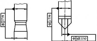
Expansion bolts with a conical end, installed in drilled holes in finished foundations and secured using expanding collets or cement-sand mortar using the vibro-immersion method, are shown in Fig. 5.
Rice. 5. Bolts, spacer type with a conical end, installed in drilled holes in finished foundations
and ¾ secured using an expanding collet (and.s. No. 539170); b, c ¾ fixed with cement-sand mortar using the vibration immersion method (a.s. No. 737573 and a.s. No. 763525)
Expansion dowels (hereinafter referred to as dowels), installed in drilled holes in building elements (walls, columns, etc.) and secured using spacer devices, are shown in Fig. 6.
Rice. 6. Spacer dowels installed in drilled holes of finished structures
a, b ¾ expansion dowel-studs (M8-M24) (AS No. 1225936); ¾ dowel-sleeve, spacer (M6-M20); 1 ¾ spacer pin; 2 ¾ expansion collet; 3 ¾ nut; 4 ¾ spacer; 5 ¾ expansion plug; 6 ¾ mounting bolt
2.3. According to operating conditions, bolts are divided into design and structural.
Design bolts include bolts that carry loads arising during the operation of building structures or equipment operation.
Structural bolts include bolts intended for fastening building structures and equipment, the stability of which against overturning or shifting is ensured by the own weight of the structure or equipment. Structural bolts are intended for straightening building structures and equipment during their installation and to ensure stable operation of structures and equipment during operation, as well as to prevent their accidental displacement.
The level of dynamism is set depending on the type and nature of the equipment.
2.4. Bolts for fastening structures and equipment must be manufactured in accordance with GOST 24379.0 “Foundation bolts. General technical conditions" and GOST 24379.1 "Foundation bolts. Design and dimensions."
The classification of bolts in accordance with the specified standards is given in table. 1.
Table 1
| Drawing | Bolt type | Nominal thread diameter d, mm | GOST 24379.1 | ||
| A | Curved | 12-48 | Type. 1 | Version 1 | |
| b | With anchor | 16-48 | Version 1 | ||
| V | stove | 56-140 | Type. 2 | Version 2 | |
| 1 | G | 100-140 | Version 3 | ||
| d | Compounds with | 24-48 | Version 1 | ||
| e | anchor plate | 56-64 | Type. 3 | Version 2 | |
| A | Removable with | 24-48 | Version 1 | ||
| 2 | b | anchor | 56-125 | Type. 4 | Version 2 |
| V | device | 56-100 | Version 3 | ||
| 3 | Bent in wells) | 12-48 | Type. 1 | Version 2 | |
| 4 | Direct on glue and with cement-sand | ||||
| vibrocaulking | 12-48 | Type. 5 | ¾ | ||
| A | With conical | Version 1 | |||
| 5 | b | the end | 12-48 | Type. 6 | Version 2 |
| V | Version 3 | ||||
2.5. Curved bolts (see Fig. 1, a) are intended for fastening building structures and technological equipment in cases where the height of the foundation does not depend on the depth of embedding of bolts in concrete.
2.6. Bolts with an anchor plate (see Fig. 1, b, c, d), which have a smaller embedment depth compared to curved bolts, are recommended for use in cases where the height of the foundation is determined by the depth of embedding of the bolts in the concrete.
2.7. Composite bolts with anchor plates (see Fig. 1, e, f) are used in cases of installation of equipment by turning or sliding (for example, when installing vertical cylindrical devices in the chemical industry). In these cases, the coupling and the lower stud with the anchor plate are installed in the foundation mass during concreting, and the upper stud is screwed into the coupling for the entire length of the thread after installing the equipment through the holes in the supporting parts.
The length of screwing the stud into the coupling must be at least 1.6 times the diameter of the bolt thread.
2.8. Bolts, curved and with an anchor plate, are installed before concreting the foundations on special conductor devices that strictly fix their design position during the concreting process.
2.9. Removable bolts (see Fig. 2) are recommended to be used mainly for fastening heavy rolling, forging, electrical and other equipment that causes large dynamic loads, as well as in cases where the bolts are subject to possible replacement during operation of the equipment.
When installing removable bolts in the foundation mass, only anchor reinforcement (anchor devices) is laid, and the stud is installed freely in the pipe after the foundation is installed.
2.10. Curved bolts, installed in the “wells” of ready-made foundations (see Fig. 3) with subsequent embedding of the well with concrete, are recommended for fastening equipment and building structures in cases where bolts cannot be installed in drilled holes.
2.11. Straight bolts on synthetic adhesives (epoxy or siloxane) and secured using a cement-sand mixture using the vibration caulking method (see Fig. 4) are recommended for fastening building structures and technological equipment with a cycle asymmetry level of r ³ 0.6 ¾ for bolts on synthetic adhesives and r ³ 0.8 ¾ for bolts with vibrocaulking.
Bolts secured with epoxy adhesive can be operated at a design ambient temperature of up to minus 40°C and when concrete is heated to 50°C, bolts secured with siloxane adhesive ¾ respectively up to minus 40°C and up to 100°C.
2.12. Expansion bolts, secured using an expanding collet (see Fig. 5, a), and expansion dowels (see Fig. 6) are intended for fastening building structures and equipment experiencing static and vibration loads (r ³ 0.9).
2.13. Bolts with a conical end, secured with cement-sand mortar using the vibration-immersion method (see Fig. 5, b, c), are recommended for fastening building structures and technological equipment, with the exception of equipment that causes significant dynamic and shock loads (press-forging equipment, rolling cages, high-power electric motors, etc.).
Note. Bolts with a conical end of version 2 are made by upsetting, version 3 ¾ by screwing on a conical sleeve.
2.14. Bolts installed in drilled holes in finished foundations are not allowed to be used for fastening load-bearing columns of buildings equipped with overhead cranes, as well as for high-rise buildings and structures for which wind load is the main one.
To fasten these structures, it is allowed to use bolts with a conical end, installed by vibration immersion.
In this case, the depth of embedding of bolts must be at least 20 d.
When taking measures to ensure the reliability and durability of anchoring (increased embedment depth, additional anchoring devices, etc.), it is allowed to fasten these structures with bolts of other types installed in drilled holes in finished foundations, in agreement with the organization ¾ developer of these bolts.
2.15. To fasten technological equipment, it is allowed to install bolts with a diameter of over 48 mm in wells with an appropriate feasibility study and in the presence of drilling equipment.
2.16. Expansion dowels are intended for securing mainly plumbing, electrical and ventilation equipment, as well as finishing elements, cladding, etc.
The designs and dimensions of spacer dowels are given in the appendix. 1.
2.17. Dowels are intended for structural fastening of various small equipment, as well as metal structures, decorative trim parts and other elements on foundations, walls and other building structures made of concrete, reinforced concrete and brick.
Technical documentation for dowels was developed by VNIImontazhspetsstroy.
2.18. Fastening units with bolts with an expanding collet and expansion dowels can be put into operation immediately after installing the bolts and dowels.
3. Bolt calculation
3.1. Loads acting on bolts are divided into static and dynamic according to the nature of the impact. The magnitude, direction and nature of the operating loads from the equipment on the bolts must be indicated in the assignment for designing foundations for the equipment.
3.2. The steel rating of design bolts operated at design winter outside air temperatures up to minus 65°C inclusive must be assigned in accordance with the instructions in Table. 2.
table 2
| estimated winter outside air temperature, °C | From ¾40°С and above | From ¾40 to ¾50°С | From ¾51 to ¾65°С |
| steel grade | VSt3kp2, VSt3ps2, St20 | 09G2S-6, 10G2S1-6 | 09G2S-8, 10G2S1-8 |
Note. Bolts may be made from other grades of steel, the mechanical properties of which are not lower than the properties of steel grades indicated in Table. 2.
3.3. Bolts for fastening building structures at outside temperatures of minus 40° C and above should be made of carbon steel grade VSt3kp2 (GOST 380), and for fastening equipment ¾ of carbon steel grade VSt3ps2 (GOST 380) or structural steel grade St20 (GOST 1050).
For bolts with a diameter of 56 mm or more, it is permissible to use low-alloy steel grades 09G2S-2 and 10G2S1-2 (GOST 19281) under the same temperature conditions.
3.4. For fastening vessels and apparatus intended for processing and storing explosive products, as well as for fastening column-type devices at a design winter outdoor temperature of up to minus 30°C inclusive, steel grade VSt3ps3 should be used (instead of steel grade VSt3ps2); at outside air temperatures from minus 31 to 40°C ¾ steel grade St20 according to GOST 1050.
3.5. At a design winter outdoor temperature of minus 65°C, low-alloy steel grades 09G2S-8 and 10G2S1-8 must have an impact strength of at least 30 J/cm2 (3 kgf×m/cm2) at a test temperature of minus 60°C.
3.6. In all cases, structural bolts may be made from steel grade VSt3kp2 in accordance with GOST 380.
3.7. The calculated tensile strength of bolt metal Rba should be taken according to table. 3.
Table 3
| Calculated tensile strength of metal Rwa, MPa | |||
| Bolt diameter, mm | VSt3ps2, VSt3kp2, St20 | 09G2S | 10G2S1 |
| 10 ¾ 30 | 145 | 185 | 190 |
| 36 ¾ 56 | 145 | 180 | 180 |
| 64 ¾ 80 | 145 | 175 | 170 |
| 90 ¾ 100 | 145 | 170 | 170 |
| 110 ¾ 140 | 145 | 170 | 165 |
3.8. All bolts must be tightened to the pre-tightening value F, which for static loads should be taken equal to: f = 0.75 R, for dynamic loads F = 1.1 R, where R ¾ the design load acting on the bolt.
For building structures (steel columns of buildings, etc.), bolts can be tightened with standard hand tools with maximum force (all the way) on the bolt.
3.9. The cross-sectional area of the bolts (by thread) should be determined from the strength condition using the formula
Asa = ko R/ Rva (1)
where ko = 1.35 ¾ for dynamic loads; ko = 1.05 ¾ for static loads.
For removable bolts with anchor plates installed freely in a pipe, the coefficient ko for dynamic loads is taken equal to 1.15.
3.10. Under the action of dynamic loads, the cross-section of the bolts, calculated using formula (1), should be checked for endurance using the formula
Asa = 1.8 cm ko R/ a Rwa (2)
where c ¾ load factor taken according to table. 4, depending on the bolt design; m ¾ coefficient taking into account the scale factor taken according to table. 5, depending on the bolt diameter; a ¾ coefficient taking into account the number of loading cycles, taken according to table. 6.
Table 4
| Bolt designs | With a bend | With anchor plate | Direct | Conical (spacer) | |
| Bolt diameter (thread) d, mm | 12 ¾ 48 | Deaf 12 ¾ 140 | Removable 56 ¾ 125 | 12 ¾ 48 | 6 ¾ 48 |
| 1 | 2 | 3 | 4 | 5 | 6 |
| Sketches | |||||
| The embedment depth H is taken from the condition Rwa = 145 kPa | |||||
| Maximum embedment depth H | 25 d | 15 d | 30 d | 10 d | 10d (8d)* |
| Minimum distance between bolt axes | 6 d | 8d | 10 d | 5 d | 8d |
| Minimum distance from the axis of the bolts to the edge of the foundation | 4 d | 6 d | 6 d | 5 d | 8d |
| Load factor c | 0,4 | 0,4 | 0,25 | 0,6 | 0,55 |
| Tightening stability coefficient k | 1,9 (1,3)** | 1,9 (1,3) | 1,5 | 2,5 (2) | 2,3 (1,8) |
* The embedment depth for bolts with a diameter of less than 16 mm is given in brackets.
* The values of the coefficient k of static loads are given in parentheses.
Table 5
| Bolt diameter, mm | 10-12 | 16 | 20-24 | 30-36 | 42-48 | 56-72 | 80-90 | 100-125 | 140 |
| m | 0,9 | 1 | 1,1 | 1,3 | 1,6 | 1,8 | 2 | 2,2 | 2,5 |
Table 6
| Number of loading cycles | 0,05×10⁶ | 0,2×10⁶ | 0,8×10⁶ | 2×10⁶ | 5×10⁶ and more |
| a | 3,15 | 2,25 | 1,57 | 1,25 | 4 |
3.11. When calculating fastenings of building structures, the pre-tightening force and cross-sectional area of the bolts should be determined as for static loads, unless there are special instructions in the project.
3.12. When installing bolts in a group for fastening equipment (Fig. 7), the value of the design load P per bolt should be determined for the most loaded bolt using the formula
, (3)
where N ¾ calculated normal force; M ¾ design bending moment; n ¾ total number of bolts; y1 ¾ distance from the axis of rotation to the most distant bolt in the stretched joint area; yi ¾ distance from the axis of rotation to the i-th bolt, taking into account both stretched and compressed bolts.
Rice. 7. Calculation scheme for determining forces during group installation of bolts for fastening process equipment
The axis of rotation may be taken to pass through the center of gravity of the supporting surface of the equipment.
3.43. For through steel columns with separate bases, the value of the calculated tensile load per bolt should be determined using the formula
P = (M ‑ Nв) / nh, (4)
where M and N ¾ bending moment and longitudinal force in the through column at the level of the top of the foundation; h ¾ distance between the axes of the column branches; n ¾ number of bolts for fastening the column branch; ¾ the distance from the center of gravity of the column section to the axis of the compressed branch.
3.14. For the bases of solid steel columns (Fig. the value of the design load per one stretched bolt should be determined by the formula
Р = (Rв в s x ‑ N) / n (5)
where N ¾ longitudinal force in the column; Rв ¾ calculated resistance of foundation concrete to axial compression, taken depending on the class of concrete according to table. 7; n ¾ number of stretched bolts located on one side of the column base; bs ¾ width of the base plate of the column; x ¾ the height of the compressed zone of concrete under the base plate of the column base, determined by the formula
, (6)
where la ¾ is the distance from the resultant of the forces in the stretched bolts to the opposite edge of the slab; C ¾ distance from the column axis to the bolt axis; e0¾ eccentricity of load application.
Rice. 8. Calculation diagram of forces in the support section for solid steel columns
Table 7
| Concrete class | AT 10 | B12.5 | B15 | IN 20 | B25 | B30 |
| Rв, MPa | 5,8 | 7,3 | 8,7 | 11,5 | 14,5 | 17 |
The height of the compressed zone x is limited by the condition
x £ xR la, (7)
Where
xR = . (8)
In formula (8) Rв and Rва in MPa.
In cases where x > xR la, the class of the foundation concrete should be increased, either the base slab should be increased, or indirect reinforcement should be provided.
3.15. The magnitude of the pre-tightening force of the bolts ¾ for the perception of horizontal (shear) forces in the plane of interface of the equipment with the foundation for shear-resistant connections (which do not allow the supporting structure to shift by the amount of the gap between the bolt rod and the walls of the hole in the glass) should be determined by the formula
F1 = k(Q‑Nf)/nf(9)
where Q ¾ calculated shear force acting in the reference plane; N ¾ normal force; f ¾ friction coefficient, taken equal to 0.25; n ¾ number of bolts; to ¾ tightening stability coefficient, taken according to table. 4.
3.16. Under the combined action of vertical and horizontal (shear) forces, the magnitude of the tightening force F0 should be determined by the formula
F0 = F + F1 / k. (10)
The cross-sectional area of the bolt along the thread in this case is determined by the formula
Аsa = (k ko P + F1) / k Rba (11)
where k ¾ is the coefficient of tightening stability, taken according to the table. 4.
3.17. In shear-tolerant connections, the shear force Q is perceived due to the shear resistance of the bolt rod and is determined by the formula
Q £ 0.6 Аsa Rва n. (12)
Under the combined action of axial P and shear Q forces, their permissible values can be determined by the formulas:
Р £ 0.6 Аsa Rва n; (13)
Q £ 0.4 Аsa Rва n; (14)
where n ¾ number of bolts.
The magnitude of the pre-tightening force of the bolts F2 in this case should be assigned according to the formula
F2 = to Asa Rba / 2. (15)
3.18. The shear force Q acting in the plane of the bending moment for through steel columns having separate bases for the column branches can be perceived by the friction force under the compressed column branch and determined from the condition
Q £ f / h, (16)
where the notations are the same as in formula (4).
The shear force of solid steel columns, as well as for through columns under the action of a shear force perpendicular to the plane of the bending moment (tie columns), can be perceived by the friction force from the action of the longitudinal force and the tightening force of the bolts and determined by the formula
Q £ f (n Asa Rwa / 4 +N), (17)
where N ¾ the minimum longitudinal force corresponding to the loads from which the shear force is determined; p ¾ the number of bolts for fastening a compressed branch of a column or the number of compressed bolts located on one side of the column base (for solid type columns); f ¾ friction coefficient, taken equal to 0.25; Аsa ¾ cross-sectional area of one bolt.
3.19. Bolts must be tightened, as a rule, with control of the torque value Mkr, N×m, the value of which should be determined by the formula
Mkr = F x, (18)
where F ¾ bolt pre-tightening force; x ¾ coefficient taking into account the geometric dimensions of the thread, friction at the end of the nut and in the thread, taken according to table. 8.
Table 8
| Bolt diameter, mm | x, m | Bolt diameter, mm | x, m |
| 10 | 2×10⁻³ | 56 | 1,4×10⁻² |
| 12 | 2,4×10⁻³ | 64 | 1,7×10⁻² |
| 16 | 3,2×10⁻³ | 72 | 1,9×10⁻² |
| 20 | 4,4×10⁻³ | 80 | 2,1×10⁻² |
| 24 | 5,8×10⁻³ | 90 | 2,3×10⁻² |
| 30 | 7,5×10⁻³ | 100 | 2,5×10⁻² |
| 36 | 9×10⁻³ | 110 | 2,8×10⁻² |
| 42 | 1,1×10⁻² | 125 | 3,2×10⁻² |
| 48 | 1,2×10⁻² | 140 | 3,5×10⁻² |
3.20. The minimum embedment depth of bolts made of steel grade VSt3kp2 in the foundation (dimension H) for concrete class B12.5 should be taken according to table. 4.
For other grades of steel bolts or another class of concrete, the embedment depth Ho should be determined using the formula
But³ N t1. t2, (19)
where t1 ¾ is the ratio of the calculated tensile strength of concrete of class B12.5 to the calculated resistance of concrete of the accepted class; t2 ¾ the ratio of the calculated tensile strength of the metal bolts of the accepted steel grade to the calculated tensile strength of steel grade VSt3kp2.
For bolts with a diameter of 24 mm or more installed in wells of finished foundations, the coefficient t1 should be taken equal to one.
The values of the calculated tensile resistance of concrete Rвt depending on the class of concrete are given in table. 9.
Table 9
| Concrete class | AT 10 | B12.5 | B15 | IN 20 | B25 | B30 |
| Rвt, MPa | 0,61 | 0,7 | 0,8 | 0,95 | 1,1 | 1,2 |
For the same materials, the minimum embedment depth of the spacer dowel-sleeve (see Fig. 6, c) should be taken H = 6 d, taking into account the values of the following design parameters: load factor c = 0.4; tightening stability coefficient k = 1.3 (under dynamic influences k = 1.9); the distance between the axes of the dowels is ¾ at least 5 d, from the edge of the foundation to the axis of the dowel ¾ 6 d.
3.21. The embedment depth of expansion dowels installed in soft materials (brick, expanded clay concrete) should be increased by 2 d compared to the embedment depth of similar dowels installed in structures made of class B12.5 concrete.
3.22. For structural bolts with bends, the depth of embedment in concrete can be taken equal to 15 d, for bolts with anchor plates ¾ 10 d, and for bolts installed in wells, ¾ 5 d.
3.23. The smallest permissible distances between the axes of the bolts and from the axis of the outer bolts to the edges of the foundation are given in Table. 4.
The distances between the bolts, as well as from the axis of the bolts to the edge of the foundation, can be reduced by 2 d with a corresponding increase in the embedment depth by 5 d.
The distance from the axis of the bolt to the edge of the foundation can be reduced by another diameter if there is special reinforcement of the vertical edge of the foundation at the location where the bolt is installed.
In all cases, the distance from the axis of the bolt to the edge of the foundation should not be less than 100 mm for bolts with a diameter of up to 30 mm inclusive, 150 mm for bolts with a diameter of up to 48 mm and 200 mm for bolts with a diameter of more than 48 mm.
3.24. When installing paired bolts, for example, to secure load-bearing steel columns of buildings and structures, a common anchor plate should be provided with a distance between holes equal to the design size between the axes of the bolts, or single bolts should be installed with a “stagger” in depth. The embedment depth of paired bolts with a distance between their axes of 8 d or more should be assigned 15 d, with a distance of less than 8 d ¾ equal to 20 d.
The distance from the edge of the slab to the axis of the bolt should be at least 2 d, while the area of the anchor plate should be at least 32 d2.
3.25. The calculated cross-sectional areas of the bolts (by thread) depending on their diameter are given in Table. 10.
Table 10
| Bolt thread diameter d | Calculated cross-sectional area of bolts on Asa thread, cm2 | Bolt thread diameter d | Calculated cross-sectional area of bolts on Asa thread, cm2 |
| M 10 | 0,571 | M 56 | 20,29 |
| M 12 | 0,842 | M 64 | 26,75 |
| M 16 | 1,57 | M 72x6 | 34,58 |
| M 20 | 2,45 | M 80x6 | 43,44 |
| M 24 | 3,52 | M 90x6 | 55,91 |
| M 30 | 5,60 | M 100x6 | 69,95 |
| M 36 | 8,26 | M 110x6 | 85,56 |
| M 42 | 11,2 | M 125x6 | 111,91 |
| M 48 | 19,72 | M 140x6 | 141,81 |
3.26. The diameters of structural bolts must be specified in the foundation design specifications. In the absence of instructions, the diameters of structural bolts are assigned in accordance with the diameter of the holes in the supporting parts of the equipment.
Examples of bolt calculations are given in appendix. 2 of this Manual.
4. Formation of wells in concrete and reinforced concrete
4.1. The formation of wells in concrete and reinforced concrete is carried out using a mechanized tool, the technical characteristics of which are given in adj. 3 of this Manual.
4.2. The formation of wells in concrete and reinforced concrete should be done according to markings or through holes for foundation bolts in the frames of pre-calibrated equipment.
4.3. Marking of bolt installation locations is carried out: a) using generally accepted methods of geodetic marking, and it is recommended to mark the axes of the equipment and the axes of the holes with a core using oil paint; b) according to a template (taken from the anchor plan) using it as a conductor; c) by pre-installing the equipment with punching the bolt locations through the hole in the frame.
4.4. The marking of holes must be made in strict accordance with the dimensions on the drawings.
The error in marking holes for bolts should be no more than 50% of the permissible deviations in the locations of the axes of the foundation bolts.
The accuracy of marking the axes of the holes must be no less than the value determined by the following relationship:
, (20)
where dх and dу ¾ the magnitude of deviations from the nominal dimensions, coordinating the position of the axis of the holes; D ¾ diameter of the bolt hole in the equipment frame; d ¾ diameter of the foundation bolt.
4.5. The technology for forming wells must meet the requirements of the current technical specifications for the work and safety regulations.
4.6. To form wells with a diameter of more than 60 mm using pneumatic hammer drills, it is recommended to drill in two stages. First, a hole with a diameter of 50¾60 mm is drilled, and then ¾ of the required diameter.
4.7. Drilling wells in reinforced concrete with top reinforcement, if necessary, can be done by cutting through the reinforcement that gets into the well section using oxygen-acetylene cutters or the electric arc method.
4.8. To drill holes for conical bolts and dowels (see Fig. 5, 6), electric and pneumatic hammer drills or drilling machines equipped with diamond ring drills should be used.
4.9. When drilling with diamond core bits and bits equipped with carbide alloys, a water supply is required for cooling in the cutting zone. Water consumption depends on the diameter of the well being drilled. With a well diameter of up to 25 mm, water consumption is 1.5 l/min, and with a diameter of more than 25 mm ¾ up to 2.5 l/min.
4.10. The diameter of the hole for straight bolts on synthetic adhesives (epoxy or siloxane) should be 8-12 mm larger than the diameter of the bolt.
4.11. The diameter of the wells for straight bolts secured using a cement-sand mixture using the vibration caulking method is determined by the dimensions of the sealing device (see Appendix 5).
4.12. The diameter of the wells for conical bolts secured using an expanding collet and the permissible deviations in the dimensions of the wells are taken according to table. eleven.
Table 11
| Bolt diameter, mm | 12 | 16 | 20 | 24 | 30 | 36 | 42 | 48 |
| Well diameter, mm | 16 | 22 | 28 | 32 | 40 | 50 | 60 | 68 |
| Permissible deviations, mm |
Foundation Fasteners
Foundation bolts GOST 24379.1−2012 are used for concrete work.
After installation, they create a strong adhesion, which determines how reliable the fastening will be, as well as the durability of the building.
Such devices are used for various types of work:
- Repair of foundations.
- Connections between the extension and the house.
- Fixing the prefabricated grillage.
- Installation of heavy stationary equipment.