Home / Gadgets
From almost improvised materials. Despite all its simplicity, the metal detector works, it can find a coin at a depth of up to 10 cm, a pan at a depth of 30 cm, and the device sees a sewer hatch at a depth of 60 cm. This is of course not much, but for such a simple device it’s pretty good. However, if you work with it on the beach or just build it for informational purposes, then you won’t waste your time.
Materials and tools for homemade work: - a complete list of board parts can be seen in the diagram, it includes the K176LA7 microcircuit; — wire for the coil (PEV-2 0.08...0.09 mm); — armored magnetic circuit; - epoxy; - headphones; - soldering iron with solder; - materials for creating a bar, body, and so on.
Metal detector manufacturing process:
Step one. A few words about the scheme
L1 needs to be wound on a frame with three sections with a tuning core and placed in an armored magnetic core with a diameter of 8.8 mm, made of 600NN ferrite. In total, the coil has 200 turns of PEV-2 wire 0.08...0.09 mm.
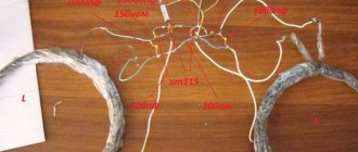
Coil L2 is made from a piece of aluminum tube with a diameter of 6-9 mm and a length of 950 mm.
You need to thread 18 pieces of wire with good insulation through it. Next, the tube needs to be bent using a mandrel; it should be approximately 15 cm in diameter. The wire sections are connected in series. The inductance of this type of coil should be within 350 μH. There is no need to short-circuit the ends of the tube, but one of them must be connected with a common wire.
For the circuit described above, the author used a rubber hose with a metal base inside, as well as a solid wire coated with varnish. To avoid damaging the insulation, tweezers with rubber tubes at the ends were used. The winding must be fixed as carefully as possible, otherwise the device will give false alarms.
It is important to note the fact that the cable running from the board to the coil must be shielded.
Step two. Further assembly and configuration
To adjust, the capacitor knob must be turned to the middle position, and then by rotating the tuning core L1, you need to ensure that there is no beat in the headphones. The setting will be correct if, when turning the variable capacitor knob to a small angle, a hum is heard in the headphones.
The adjustment is carried out at a distance of at least one meter from massive metal objects.
The author was able to increase the sensitivity of the device if he screwed in the core of the tuning coil all the way, and by adjusting the setting using a variable capacitor, achieved almost complete absence of sound in the headphones. However, if you turn on the headphones at full power, the sound will be quiet.
If it turns out that the sound in the headphones is not audible at all, you need to check the presence of a U-shaped signal at pins 4 of DD1 and DD2; for such purposes you will need an oscilloscope. There should be a mixture of signals at pin 11 and 8 of DD3.
It should also be noted that the original circuit indicates a resistance of R3 of 300 kOhm, but the headphones will not work with this resistance. It needs to be replaced with 3 kOhm. Instead of 5600 pF capacitors, the author also used 4700 pF capacitors, since the former could not be found.
The disadvantages of the circuit include the fact that the chamber is sensitive to ambient temperature; therefore, the device must be constantly adjusted with a variable capacitor, achieving zero beats.
Step three. The final stage of assembly
The author recommends filling the coil with epoxy, this will allow the wires to be securely fixed.
Otherwise, there will inevitably be false positives, since during the search you have to hit rocks, sticks and other obstacles, and the coil can be easily damaged. Instead of epoxy, wax or plasticine is suitable, which needs to be melted and poured. Paraffin should not be used, as it becomes brittle after hardening and has no elasticity. If the choice fell on plasticine, then you need to take care that it does not leak out when heated in the sun. Among other things, gently replace resistor R3 in the circuit; its value should be 300 kOhm.
You also need to adjust the frequency of the reference generator so that confident and clear clicks are heard in the headphones. The sensitivity of the device is determined by the frequency of clicks; the lower it is, the better. With these settings, the author finds a USSR penny coin at a depth of 10 cm, which lies horizontally. If you make the click frequency high, the presence of metal under the search coil can be determined by a change in sound.
The author also assembled another such device and discovered a problem - no sound in the headphones. The solution was to remove capacitor C7 from the circuit. The author also removed the volume control, since the sound itself became quieter. With this modification, the device did not lose sensitivity.
The plastic housing for the device can be bought at a radio store; it cost the author 31 rubles. To shield the circuit, you need to cut out a “shirt” from cardboard and wrap it in foil. The edges of the foil are attached to the cardboard with tape, then the wire is attached using a stapler and connected to the minus.
You also need to install an electrolytic capacitor of 47-100 uF in the circuit after turning on the power with a voltage of at least 10V.
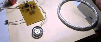
Let's look at a simple metal detector based on the K561LA7 microcircuit and a sound amplifier. Power supply is 9 volts. Since the current consumption is small, the crown batteries last for a long time. According to the characteristics, the device has average detection depth indicators, worthy for such a simple circuit. There are similar metal detectors based on K561LA9 microcircuits, but they do not provide a significant increase in performance, so we give preference to assembling this simplified circuit.
In metal detection, the main role is played by the sensor, consisting of a round coil, a housing and a connecting wire to the control circuit (Fig. 1).
The appearance of metal in the sensor's coverage area affects the inductance of the coil, which, in turn, affects the frequency of the search circuit on the microcontroller. The final logical element of the microcircuit compares the reference frequency value and the frequency of the search circuit and, through an amplifier, outputs the difference in the form of a tonal sound in the dynamics.
Manufacturing the sensor
Metal detector circuits for different devices are completely different from each other. However, a well-assembled sensor can be used as a universal one for various metal detectors operating on the same operating principle.
To wind the sensor we use varnished PEV or PEL wire with a diameter of 0.5 - 0.7 mm, which can be easily found in the store or in old CRT TVs and monitors (Fig. 2).
With a coil diameter of 20 cm, we wind 100 turns of wire. For other diameters, we change the number of turns, calculating that at 25 and 15 cm in diameter, 80 and 120 turns are wound, respectively. After completing the winding, wrap it tightly with electrical tape, leaving a margin at the beginning and end of the wire.
We make a Faraday shield to eliminate various interferences in the coil and microcontrollers. It is necessary to wrap the coil over the electrical tape with food foil. At the end of the winding we do not connect the foil and leave a gap of 2-3 cm. On top of the foil we randomly wind a little uninsulated wire of a small cross-section (Fig. 3).
In several places you can solder the wire and foil. We wrap all this again with electrical tape.
After these steps, we should have an insulated coil with two winding terminals and a screen terminal. We connect them with a shielded cable from video or audio equipment. We connect the cable screen to the wire from the foil, and the cable cores to the wires from the coil. We solder all this and securely insulate it with electrical tape. At the end of the cable we attach a plug with high-quality contacts. The best option is if they are gold plated or silver. The plug can be found in cables for various equipment, and we also take the connector there.
All that remains is to make the housing for the coil. You can use two round disks made of dielectric material - plywood, thick cardboard or plastic. We place a winding between the disks. Then, using plastic fasteners, which can be purchased at a plumbing store, we tightly fasten these two disks. To search in an aquatic environment, you can seal the sensor with epoxy resin or special sealants.
On the top disk we screw or glue ears made of plastic or other dielectric material. They will be needed for attachment to the bar (Fig. 4).
Text of the book “Metal Detectors”
Chapter 3 Metal detectors on microcircuits
Descriptions of metal detectors of various types, made on microcircuits, have been published in the specialized literature for many years. At the same time, the proposed designs differ not only in the element base used, but also in the degree of complexity. This chapter discusses only some of the circuit solutions that formed the basis for both simple devices that beginner radio amateurs can assemble, and more complex designs.
3.1. A simple metal detector based on the K155LA3 chip
Beginning radio amateurs can be recommended to repeat the design of a simple metal detector, the basis for which was a diagram that was repeatedly published in the late 70s of the last century in various domestic and foreign specialized publications. This metal detector, made on just one K155LA3 type chip, can be assembled in a few minutes.
Schematic diagram
The proposed design is one of the many options for metal detectors of the BFO (Beat Frequency Oscillator) type, that is, it is a device based on the principle of analyzing the beats of two signals close in frequency (Fig. 3.1). Moreover, in this design, the change in beat frequency is assessed by ear.
Rice. 3.1. Schematic diagram of a metal detector based on the K155LA3 chip
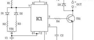
The basis of the device is a measuring and reference oscillator, an RF oscillation detector, an indication circuit, and a supply voltage stabilizer.
The design in question uses two simple LC oscillators made on the IC1 chip. The circuit design of these generators is almost identical. In this case, the first generator, which is the reference one, is assembled on elements IC1.1 and IC1.2, and the second, measuring or tunable generator, is made on elements IC1.3 and IC1.4.
The reference oscillator circuit is formed by capacitor C1 with a capacity of 200 pF and coil L1. The measuring generator circuit uses a variable capacitor C2 with a maximum capacitance of approximately 300 pF, as well as a search coil L2. In this case, both generators are tuned to an operating frequency of approximately 465 kHz.
The outputs of the generators are connected through decoupling capacitors SZ and C4 to an RF oscillation detector made on diodes D1 and D2 using a rectified voltage doubling circuit. The load of the detector is the BF1 headphones, on which the signal of the low-frequency component is isolated. In this case, capacitor C5 shunts the load at higher frequencies.
When the search coil L2 of the oscillatory circuit of a tunable generator approaches a metal object, its inductance changes, which causes a change in the operating frequency of this generator. Moreover, if there is an object made of ferrous metal (ferromagnetic) near coil L2, its inductance increases, which leads to a decrease in the frequency of the tunable generator. Non-ferrous metal reduces the inductance of coil L2, and increases the operating frequency of the generator.
The RF signal, generated by mixing the signals of the measuring and reference oscillators after passing through capacitors C3 and C4, is fed to the detector. In this case, the amplitude of the RF signal changes with the beat frequency.
The low-frequency envelope of the RF signal is isolated by a detector made of diodes D1 and D2. Capacitor C5 provides filtering of the high-frequency component of the signal. Next, the beat signal is sent to the BF1 headphones.
Power is supplied to the IC1 microcircuit from a 9 V source B1 through a voltage regulator formed by a zener diode D3, a ballast resistor R3 and a control transistor T1.
Details and design
To manufacture the metal detector in question, you can use any breadboard. Therefore, the parts used are not subject to any restrictions related to overall dimensions. Installation can be either mounted or printed.
When repeating a metal detector, you can use the K155LA3 microcircuit, consisting of four 2I-NOT logic elements powered by a common DC source. As capacitor C2, you can use a tuning capacitor from a portable radio receiver (for example, from a Mountaineer radio receiver). Diodes D1 and D2 can be replaced with any high-frequency germanium diodes.
The L1 coil of the reference oscillator circuit should have an inductance of about 500 μH. It is recommended to use, for example, an IF filter coil of a superheterodyne receiver as such a coil.
Measuring coil L2 contains 30 turns of PEL wire with a diameter of 0.4 mm and is made in the form of a torus with a diameter of 200 mm. It is easier to make this coil on a rigid frame, but you can do without it. In this case, any suitable round object, such as a jar, can be used as a temporary frame. The turns of the coil are wound in bulk, after which they are removed from the frame and shielded with an electrostatic screen, which is an open tape of aluminum foil wound over a bundle of turns. The gap between the beginning and end of the tape winding (the gap between the ends of the screen) must be at least 15 mm.
When making coil L2, special care must be taken to ensure that the ends of the shielding tape do not short-circuit, since in this case a short-circuited turn is formed. In order to increase mechanical strength, the coil can be impregnated with epoxy glue.
For the source of sound signals, you should use high-impedance headphones with the highest possible resistance (about 2000 Ohms). For example, the well-known TA-4 or TON-2 telephone will do.
As a power source B1, you can use, for example, a Krona battery or two 3336L batteries connected in series.
In a voltage stabilizer, the capacitance of electrolytic capacitor C6 can range from 20 to 50 μF, and capacitance C7 can range from 3,300 to 68,000 pF. The voltage at the output of the stabilizer, equal to 5 V, is set by trimming resistor R4. This voltage will be maintained unchanged even if the batteries are significantly discharged.
It should be noted that the K155LAZ microcircuit is designed to be powered from a 5 V DC source. Therefore, if desired, you can exclude the voltage stabilizer unit from the circuit and use one 3336L battery or similar as a power source, which allows you to assemble a compact design. However, the discharge of this battery will very quickly affect the functionality of this metal detector. That is why a power supply is needed that provides a stable voltage of 5 V.
It should be admitted that the author used four large round imported batteries connected in series as a power source. In this case, a voltage of 5 V was generated by an integrated stabilizer of type 7805.
The board with the elements located on it and the power supply are placed in any suitable plastic or wooden case. A variable capacitor C2, a switch S1, as well as connectors for connecting the search coil L2 and headphones BF1 are installed on the housing cover (these connectors and switch S1 are not indicated on the circuit diagram).
Setting up
As when adjusting other metal detectors, this device should be adjusted in conditions where metal objects are at least one meter away from the L2 search coil.
First, using a frequency meter or oscilloscope, you need to adjust the operating frequencies of the reference and measuring generators. The frequency of the reference oscillator is set to approximately 465 kHz by adjusting the core of the coil L1 and, if necessary, selecting the capacitance of the capacitor C1. Before adjustment, you will need to disconnect the corresponding terminal of capacitor C3 from the detector diodes and capacitor C4. Next, you need to disconnect the corresponding terminal of capacitor C4 from the detector diodes and from capacitor C3 and by adjusting capacitor C2 set the frequency of the measuring generator so that its value differs from the frequency of the reference generator by approximately 1 kHz.
After all connections have been restored, the metal detector is ready for use.
Operating procedure
Carrying out search work using the metal detector considered does not have any special features. In practical use of the device, the variable capacitor C2 should be used to maintain the required frequency of the beat signal, which changes when the battery is discharged, the ambient temperature changes, or the deviation of the magnetic properties of the soil occurs.
If during operation the signal frequency in the headphones changes, this indicates the presence of a metal object in the coverage area of the L2 search coil. When approaching some metals, the frequency of the beat signal will increase, and when approaching others, it will decrease. By changing the tone of the beat signal, with some experience, you can easily determine what metal, magnetic or non-magnetic, the detected object is made of.
3.2. A simple metal detector based on the K176LE5 chip
As mentioned earlier, metal detector circuits that operate on the principle of analyzing the frequency of a beat signal that occurs when two signals of similar frequency are mixed (BFO principle) are very popular among novice radio amateurs. Such devices are easy to manufacture and set up, as can be seen by looking at the following design.
Schematic diagram
As in the metal detector discussed in the previous section, this device is assembled on just one chip (Fig. 3.2). However, the differences lie not only in the different type of microcircuit used, but also in the circuitry of the reference and measuring generators. A slightly different design of the circuit made it possible to do without a variable capacitor, and also to use only one inductor.
Rice. 3.2. Schematic diagram of a metal detector based on the K176LE5 chip
The basis of the device is a measuring and reference oscillator, an RF vibration detector and an indication circuit.
As in the mentioned design, the device in question uses two simple generators made on elements of the IC1 microcircuit. In this case, the first generator, which is the reference one, is assembled on elements IC1.1 and IC1.2, and the second, measuring or tunable generator is made on elements IC1.3 and IC1.4.
The operating frequency of the reference oscillator depends on the total resistance of resistors R1 and R2, as well as on the capacitance of capacitor C1. The tuning resistor R1 provides a rough change, and the variable resistor R2 provides a smooth change in the frequency of the generator. The frequency of the measuring generator depends on the capacitance of capacitor C2 and the inductance of coil L1, which is a search coil.
The outputs of both generators are connected through decoupling capacitors C3 and C4 to an RF oscillation detector made on diodes D1 and D2 using a rectified voltage doubling circuit.
From the output of the detector, the low-frequency signal is supplied directly to the BF1 headphones. Capacitor C5 provides load shunting at higher frequencies.
When the search coil L1 of the oscillatory circuit of the tunable generator approaches a metal object, its inductance changes, which causes a change in the operating frequency of the generator. If there is a ferrous metal object near coil L1, its inductance increases, which leads to a decrease in the frequency of the measuring generator. Non-ferrous metal reduces the inductance of coil L1, while the operating frequency of the generator increases.
The RF signal, generated by mixing the signals of the measuring and reference oscillators after passing through capacitors C3 and C4, is fed to the detector. In this case, the amplitude of the RF signal changes with the beat frequency.
The low-frequency envelope of the RF signal is isolated by a detector made of diodes D1 and D2. Capacitor C5 provides filtering of the high-frequency component of the signal. Next, the beat signal is sent to the BF1 headphones.
Power to IC1 is supplied from source B1 with a voltage of 9 V.
Details and design
All parts of a simple transistor metal detector, with the exception of the search coil L1, resistors R1 and R2, connectors X1 and X2 and switch S1, are located on a printed circuit board measuring 80x22 mm, made of single-sided foil getinax or textolite.
There are no special requirements for the parts used in this device. Naturally, it is recommended to use any small-sized capacitors and resistors that can be placed on a printed circuit board without any problems (Fig. 3.3).
Rice. 3.3. Printed circuit board (a) and arrangement of elements (b) of the metal detector on the K176LE5 chip
In this device, in addition to the K176LE5 microcircuit, you can use the K176LA7, K176PU1, K176PU2, K561LA7, K564LA7 or K564LN2 microcircuits.
Trimmer resistor R1 can be type SP5-2, and variable resistor R2 can be type SPO-0.5 (other small-sized resistors are also quite suitable), capacitor C6 can be type K50-12 or any other with a rated voltage of at least 10 V. The remaining capacitors can be any small-sized ceramic, for example type KM-6.
To make the L1 coil, it is recommended to use a piece of copper or aluminum tube with an internal diameter of 8-10 mm and a length of about 630 mm. Inside the tube, you should stretch a bundle of 20 pieces of PELSHO wire with a diameter of 0.5 mm, pre-stretched into a PVC tube. The duralumin tube with the wires in it must be bent according to a template into a ring with a diameter of about 200 mm. The end of the wire, which is the beginning of the first turn, should be soldered to one of the terminals of capacitor C2, the beginning of the second turn - to the end of the first turn, and so on. The end of the last turn is soldered to the second terminal of capacitor C2. The result is a coil containing 20 turns. When making coil L1, special care must be taken to ensure that the ends of the shielding tube do not short-circuit, since in this case a short-circuited turn is formed.
You can also use regular aluminum foil to make the screen. In this case, additional rigidity can be added to the design of coil L1 if it is placed between two disks made of plywood or getinax of appropriate sizes.
It is recommended to use any high-impedance headphones with a resistance of about 2000 Ohms as a source of sound signals. The well-known telephone TA-4 or TON-2 will do.
The power source for B1 can be a Krona battery or two 3336L batteries connected in series.
The printed circuit board with the elements located on it and the power supply are placed in any suitable plastic or wooden case. A tuning resistor R1 and a variable resistor R2, a connector X1 for connecting headphones BF1, and a switch S1 are installed on the housing cover.
The L1 search coil is located at the end of any convenient handle.
Setting up
The installation of the metal detector in question should be carried out in conditions where metal objects are removed from the search coil L1 at a distance of at least one meter.
First, you need to adjust the operating frequencies of the reference and measuring oscillators, having previously set the sliders of resistors R1 and R2 to the middle position. It is advisable to control the frequency setting using a frequency meter or oscilloscope. The frequency of the reference oscillator is roughly set by adjusting resistor R1, and more precisely by adjusting resistor R2. If necessary, you can select the capacitance of capacitor C1. Before making this adjustment, you will need to disconnect the corresponding terminal of capacitor C3 from the detector diodes and from capacitor C4. Next, having disconnected the corresponding terminal of capacitor C4 from the detector diodes and from capacitor C3, by selecting the capacitance of capacitor C2, you should select the frequency of the measuring generator so that its value differs from the frequency of the reference generator by approximately 500-1000 Hz.
Unfortunately, it is impossible to select a lower beat frequency to obtain high sensitivity for a number of reasons. Firstly, with such close frequencies of two generators, it is possible to “capture” the frequency of one generator by the other, which will lead to their mutual synchronization. And secondly, headphones practically do not respond to signals of low beat frequencies, at which maximum sensitivity is achieved (for example, at a beat frequency of 1-10 Hz).
After restoring all connections, by rotating the slider of resistor R1, you should achieve the lowest tone in the headphones.
If interference or malfunctions occur in the operation of the device due to the mutual influence of the generators, it is recommended to solder a capacitor with a capacity of 0.01-0.1 μF between pins 7 and 14 of the IC1 microcircuit.
Operating procedure
In practical use of the device, the required frequency of the beat signal should be maintained with a variable resistor R2. The beat frequency can change under the influence of various factors (for example, when the ambient temperature changes, deviation of the magnetic properties of the soil or battery discharge).
If during operation there is any metal object in the range of search coil L1, the signal frequency in the phones will change. When approaching some metals, the frequency of the beat signal will increase, and when approaching others, it will decrease. By changing the tone of the beat signal, with some experience, you can easily determine what metal, magnetic or non-magnetic, the detected object is made of.
3.3. A simple metal detector based on the K561LE5 chip
In addition to the metal detectors discussed in the previous sections of this chapter, there are other options for devices on microcircuits, the operation of which is based on the beating principle. One of these designs was created on the basis of a metal detector developed by I. Nechaev from Kursk (A detailed description of I. Nechaev’s device can be found in the magazine “Radio” No. 1 for 1987).
Schematic diagram
As already mentioned, the metal detector in question is one of the many variants of a BFO (Beat Frequency Oscillator) type device, that is, it is a device based on the principle of analyzing the beats of two frequencies. Moreover, in this design, the frequency change is assessed by ear.
The circuitry of this device is based on measuring and reference oscillators, a mixer and an acoustic indication circuit (Fig. 3.4). The reference and measuring oscillators are made on elements of the IC1 microcircuit.
Rice. 3.4. Schematic diagram of a metal detector based on the K561LE5 chip
The reference oscillator is assembled on element IC1.1. Negative DC feedback between the output (pin 3) and the input (pins 1, 2) of this element is carried out through resistor R1 and inductor L1. The parameters of coil L1 and resistor R1 are selected so that the element operates in the linear portion of the transfer characteristic. In this way, conditions are created for excitation of the cascade at a frequency of approximately 100 kHz, which is determined by the parameters of the circuit elements L1C1C2C3. Element IC1.1 has a high input impedance, so the quality factor of the circuit and the frequency stability of the generator are relatively high. Resistor R3 weakens the shunting effect of the element's output resistance on the circuit. If necessary, the oscillation frequency of the reference oscillator can be changed within small limits using a variable capacitor C2.
The measuring generator is made according to a similar circuit on element IC1.2. In this case, the operating frequency of this generator is determined by the parameters of the L2C4C5 circuit elements. Coil L2 is a search coil. When the search coil L2 of the oscillatory circuit of the tunable generator approaches a metal object, its inductance changes, which causes a change in the operating frequency of the generator.
Oscillations from the reference and measuring oscillators are supplied to the inputs of element IC1.3, which acts as a signal mixer. As a result, the output of element IC1.3 will contain not only signals of the fundamental frequencies of the generators, but also signals of the harmonic components of the difference and sum frequencies. One of the most powerful will be the difference frequency signal, which is allocated to resistor R4. The remaining signals are suppressed by a filter, which includes resistor R3 and capacitor C6.
The output signal through the volume control R4 is fed directly to the BF1 headphones. It is not necessary to use an additional low-frequency amplifier, since the amplitude of the output signal of element IC1.3 is several volts.
Power to IC1 is supplied from source B1 with a voltage of 9 V.
Details and design
To manufacture the metal detector in question, you can use any breadboard. Therefore, the parts used are not subject to any restrictions related to overall dimensions.
In the article by I. Nechaev, it is recommended to place the parts of this metal detector (with the exception of the search coil L2, resistor R4, connector X1 and switch S1) on a printed circuit board measuring 60x55 mm (Fig. 3.5), made of one-sided foil getinax or textolite.
Rice. 3.5. Printed circuit board (a) and arrangement of elements (b) of the metal detector on the K561LE5 chip
The unused input pins of the fourth element of IC1 must be connected to common.
In this device, you can use microcircuits of the K176, K561, K564 series, containing at least three logical elements “or-not” or “and-not”, for example, types K561LE5, K561LA7, K561LA9 or K561LE10.
It is recommended to use any variable capacitor from a small-sized radio as capacitor C2. The maximum capacitance of this capacitor must be at least 150 pF. The remaining capacitors can be any small-sized ceramic ones, for example the KLS, KM or KT types. It should be noted that to increase the thermal stability of the device, capacitors C1, C3-C5 must have a TKE no worse than M750 or M1500.
Fixed resistors can be any small-sized ones, for example type MLT-0.125. Variable resistor R4 can have a resistance from 10 to 68 kOhm. However, it is not recommended to use resistors mechanically connected to the power switch S1 as such a regulator.
The L1 coil of the reference oscillator circuit can be made on the frame from the IF circuit coil of any small-sized transistor receiver. For example, in I. Nechaev’s metal detector, this coil is wound on a three-section frame of the IF circuit of the Sokol-403 radio receiver. In this case, the L1 coil is placed in an armored core with a diameter of 8.6 mm made of 600NN ferrite with a trimmer with a diameter of 2.8 and a length of 12 mm made of the same ferrite. Coil L1 contains 200 turns of PEV-2 wire with a diameter of 0.09 mm.
To make the L2 search coil, it is recommended to use a piece of copper or aluminum tube with an internal diameter of 6–8 mm and a length of about 950 mm. Inside the tube, you should stretch a bundle of 18 pieces of MGTF wire with a diameter of 0.07 mm, pre-stretched into a PVC tube. The duralumin tube with the wires in it must be bent according to a template into a ring with a diameter of about 300 mm. The end of the wire, which is the beginning of the first turn, should be soldered to the corresponding terminal of capacitor C4, the beginning of the second turn - to the end of the first turn, and so on. The end of the last turn is soldered to the corresponding terminal of capacitor C5. The result is a coil containing 18 turns and having an inductance of approximately 350 µH.
When making coil L2, special care must be taken not to short-circuit the ends of the shielding tube, since in this case a short-circuited turn is formed.
Instead of a thin-walled tube, ordinary aluminum foil can be used to make the screen. In this case, additional rigidity can be given to the design of the L2 coil if it is placed between two plywood or getinax disks of appropriate sizes.
As a source of sound signals, you should use high-impedance headphones with the highest possible resistance (about 2000 Ohms). For example, the well-known TA-4 or TON-2 phones are suitable. When using low-impedance phones, the metal detector should be supplemented with a cascade based on the KT315B transistor, installing a resistor R3 with a resistance of 10 kOhm, and a capacitor C6 with a capacity of 1000 pF.
As a power source B1, you can use, for example, a Krona battery or two 3336L batteries connected in series.
The printed circuit board with the elements located on it and the power supply are placed in any suitable metal case. On the housing cover there are installed a variable resistor R4, connector X1 for connecting headphones BF1, connector X2 for connecting the search coil L2 and switch S1.
Setting up
As with the adjustment of other metal detectors, the adjustment of this device should be carried out in conditions where metal objects are removed from the L2 search coil at a distance of at least one meter.
First you need to set the operating frequency of the reference oscillator. To do this, initially the frequency of the reference oscillator is set equal to the operating frequency of the measuring oscillator by adjusting the position of the tuning core of the L1 coil until the sound signal in the headphones completely disappears, that is, until the beats are set to zero. First, the rotor of capacitor C2 should be installed approximately in the middle position. As a result, when the capacitor C2 knob is slightly turned in any direction, a low-pitched sound should appear in the phones. If necessary, you can use a frequency meter or oscilloscope to adjust the frequency of the reference oscillator.
The recommended frequency difference between the reference and measuring oscillators should be 400–500 Hz. In this case, the frequency of the reference oscillator must be higher than the frequency of the measuring oscillator. The choice of such a high value of the difference frequency is explained by the fact that both oscillators, the reference and the measuring ones, are made on elements of one common microcircuit crystal, and therefore parasitic connections inevitably arise between them, which are almost impossible to eliminate. This fact forces the use of beats with a frequency of more than 100–300 Hz in this metal detector, which inevitably leads to a decrease in its sensitivity.
Operating procedure
With error-free installation, serviceable parts and correct adjustment, the metal detector in question is ready for use immediately after the setup is completed.
Before starting search work with capacitor C2, it is advisable to set the beat frequency as low as possible. This will increase the sensitivity of the device, since it will ensure registration of even small changes in the frequency of the measuring generator. However, it will not be possible to select a very low beat frequency, because at this frequency the sound volume in phones will drop sharply.
If during operation the signal frequency in the headphones changes, this indicates the presence of a metal object in the coverage area of the L2 search coil. When the coil approaches objects made of magnetic metals (for example, iron, ferrite or nickel), the frequency of the beat signal will increase, and when approaching objects made of non-magnetic metals (for example, aluminum, copper or brass) it will decrease. By changing the tone of the beat signal, with some experience, you can easily determine what metal, magnetic or non-magnetic, the detected object is made of.
The volume level of the signal in the headphones is regulated by resistor R4.
Components for the circuit
Below are the main parts and their requirements necessary for high-quality assembly of the circuit:
- It is recommended to purchase capacitors at a radio store, but if you want to get them for free from old circuits, then measure the capacitance before use. The main requirement for them is temperature stability, this will save you from constant failures of the metal detector. Ceramic or mica ones are perfect. When assembling, do not forget to take into account the polarity of electrolytic capacitors - one or more stripes are drawn on the barrel on the minus side (Fig. 5). The following capacitors will be needed: electrolytic 100 µF x 16 V – 1 pc.; 1000 pF – 3 pcs.; 22 nF – 2 pcs.; 300 pF – 1 pc.
- Fixed resistors can be used as old ones, as they do not lose their characteristics over time. It is best to buy new variables to ensure accurate frequency adjustment on the chips. Particular attention should be paid to the contacts of the variable resistor, since according to the diagram, two contacts must be connected to each other, and experience shows that many beginners do not notice this. It is also necessary to ground their housing to prevent interference during adjustment. You will need 5 fixed resistors with nominal values of 22 Ohm, 1 kOhm, 4.7 kOhm, 10 kOhm, 470 kOhm and 3 variable resistors with nominal values of 1, 5 and 20 kOhm.
- Chip K561LA7 in DIP package. The counting of legs on microcircuits starts from the top counterclockwise from the key - a special recess on the case. As an analogue, you can make a metal detector using the K561LE5 or CD4011 microcircuit.
- The KT315 transistor is very common in older radio equipment. But it can be replaced with many other transistors: KT3102, BC546, 2SC639 and low-power low-frequency transistors with similar characteristics. We carefully study the terminals of the transistor before soldering; for KT315 they are located from left to right from the front part - emitter, collector, base (Fig. 6):
- We choose any low-power diode from domestic or imported manufacturers - kd522B, kd105, kd106, in4148, in4001 and others. Before soldering, check it with a multimeter so as not to confuse the anode and cathode.
- Standard headphones from a phone or mp3 player, or a miniature speaker from old equipment. If using headphones, you can use a connector or direct soldering.
- Krona 9 V battery and contacts for it (Fig. 7):
- We select the connector for the sensor cable plug in advance when manufacturing the sensor.
After assembling all the necessary parts, you can safely begin installing them according to the scheme described below.
Simple pulse metal detector "PIRAT"
DIY pulse metal detector
Pirat - stands for: PI - means pulse metal detector, and RAT - author’s website: “radioscot”. This metal detector has gained fame as a simple and inexpensive device; there are a small number of available parts that are not in short supply; with proper assembly and serviceable parts, the device works immediately, with virtually no settings.
If we compare it with a simple metal detector circuit based on frequency beats, then here the depth of metal detection is an order of magnitude better. There is no discrimination in this type of metal detector; non-ferrous and ferrous metals react almost identically. But with certain skills, you can understand what target is under the sensor. The assembly and configuration of this metal detector is much simpler than the previously considered pulse metal detector “VINTIK-PI” .
Characteristics of the PIRATE metal detector
Of course, the performance largely depends on the parts used, coil diameter, build quality, etc.
Diagram of the metal detector "PIRAT"
There are many different options for PIRATE metal detector circuits and modifications to them.
Option: generator with transistors, receiver with K157UD2
Option: generator on NE555, receiver on K157UD2
Option: generator on NE555, and receiver on TL072
with generator frequency adjustment:
Option: generator on K561LA7/LE5, receiver on K157UD2
Printed circuit board of the PIRATE metal detector
There are also many different options for PP, below are a few options.
Option: generator on NE555, receiver on K157UD2
Option: generator with transistors, receiver with K157UD2
Option: generator on NE555, receiver on TL072
Description of the scheme
The metal detector circuit consists of two main units: transmitting and receiving .
The transmitting unit consists of a pulse generator on the KR1006VI1 microcircuit (foreign analogue of NE555) and a powerful switch on the KP505A field-effect transistor (foreign analogue of IRF740, IRF840). You can install a reverse bipolar transistor with a K-E voltage of at least 200V. It can be taken from an energy-saving lamp or a mobile phone charger. To drive a powerful switch, a BC557 transistor is used.
The receiving unit is assembled on the K157UD2 microcircuit (you can assemble a foreign MS TL072), there are back-to-back limiting diodes at the input of the receiver, at the input of the second stage of the receiver there is a filter that cuts out the required part of the pulses, at the output of the second stage there is a transistor BC547, connected to its collector circuit speaker 8-50 Ohm. In place of T3, you can use almost any NPN structure transistor.
Installation of control circuit
The electrical circuit consists of the K561LA7 microcircuit, its wiring for adjustment, amplifier, power supply and speaker. The microcircuit has 4 logical elements. Two of them create the desired frequency, the third plays the role of the search part. The final logic element compares both frequencies and, at different values, outputs a positive signal to the amplifier, which supplies the amplified signal to the speaker.
The circuit of the metal detector on the chip described above is shown in Figure 8.
It is very convenient to assemble electrical circuit diagrams on a breadboard with holes (Fig. 9). Or we make a homemade printed circuit board, shown in Figure 10. The board can be made using the laser-iron method or regular drawing. We carry out baiting using any known method.
We solder the parts and solder all the remote parts with wiring - regulators, headphone jack, sensor and batteries.
After assembling the circuit, we fix it in the case. We also put the battery there. Plastic, mounting, homemade wooden and other boxes of your choice will be suitable as a case (Fig. 11).
For three regulators and the sensor connector, it is necessary to make holes corresponding to the dimensions. You can add a switch in series with the battery and also place it on the case. It is necessary to provide small holes for the speaker, or, in the case of headphones, to secure the connector tightly.
The main condition when assembling the case is accessibility, for example, for changing the battery, and, at the same time, tightness - from sudden rain. You can attach beautiful caps to the regulators, decorate the box and label the regulators with the switch.
What is a metal detector
Such a device, homemade or made in a factory, is designed to search for any metal under a layer of soil, regardless of whether it is pieces of iron, copper or something even more valuable. Such devices are used not only by gold miners, but also by various archaeological groups, patriotic communities (in search of remains and objects left in the ground after the Second World War) and even sappers when demining territories.
The shapes, as well as the circuits of metal detectors, are different. This could be a disk mounted on a handle, or it could be some kind of microphone. This does not change the essence of this device - when any metal object is detected at a shallow depth, it emits a certain sound using a built-in buzzer, signaling the discovery.
Such devices operate on the basis of the physical law according to which electromagnetic induction operates. Its components are a transmitter, which, upon receiving a signal, sends it to a warning device (audio or visual), the signal receiver itself and a buzzer or screen. Electromagnetic waves are sent to the surface and reflected. If the transmitted signal returns unchanged, nothing happens in the circuit, but provided that any metal enters the signal transmission area, the returned wave turns out to be distorted and this is recorded by the transmitter, which gives an audio or visual alert.
Assembling and setting up the device
When the sensor and control unit are ready, you need to connect them into a finished metal detector. For this you will need a barbell. It can be made from PVC pipes and adapters, which are bent to the desired size and shape by heating. You can also use a regular wooden pole, crutch or telescopic fishing rod. Which materials to choose depends on your preferences - consider weight, flexibility and length. For convenience, you can build a handle and an armrest, as well as make the bar collapsible (Fig. 12).
Next, we attach the sensor with ready-made ears to the rod. Use plastic fasteners, reliable glue or plumbing adapters. We fix the control unit in the same way.
To configure, connect the battery and sensor. Since metal detectors are sensitive devices, for proper setup it is necessary to remove all metal objects around. We turn it on and see one of two options:
If after turning on there is perfect silence or a barely audible squeak, then there are two options:
a) Generators operate at the same frequency. Such cases are rare, but they do happen. Try turning the soft R7 and rough R8 adjustment knobs. If the silence changes to a loud tonal sound, then the circuit works. We return the controls to their initial position and try using the smooth control R7 to achieve the best results, for example, complete absence of sound;
b) Circuit malfunction. We carefully recheck the entire circuit and radio components.
If there is a hum or high tone after turning on
, then we try to reduce it by rotating the coarse adjustment knob R8, and having achieved a better result, we adjust R7. If the metal detector does not respond to the rotation of the controls, then the frequency of the reference oscillator is too different from the frequency of the search circuit. In this case, we try to catch the desired frequency by changing capacitor C6 and resistor R6.
An oscilloscope can greatly simplify the entire setup. The essence of the setting is to achieve the same or similar frequency of pins 5 and 6 on the microcontroller. The frequency can be adjusted using the methods described above.
If you have mastered the assembly of this device, you can safely try to assemble a more complex metal detector using three microcircuits or a microcontroller.
Metal detector device
A metal detector is the most important tool for manually searching for metals in a chaotic natural or artificial environment.
Using such a device, you can search not only for ferrous metals, but also for gold, silver, and other precious metals. The design principle of any metal detector is based on electromagnetic effects.
Here's how typical metal detecting technology works:
- The device creates an electromagnetic field.
- A metal object, secretly located in a foreign environment, affects such a field when it comes into its sphere of influence.
- The device detects the impact of an object on the electromagnetic field and signals about it.
A large number of metal detector models operate precisely on this principle.
Technical differences in such equipment make it possible to obtain more complete information about the fact of detecting a metal object, for example:
- estimate the mass of the find;
- obtain data on the shape, size and configuration of an object;
- specify the location, including depth.
The simplest, most primitive metal detectors (usually homemade designs for searching for gold, silver and other metals by amateur enthusiasts) are assembled from ready-made devices and products that work using electromagnetic effects.
Many are familiar with the primitive, but quite workable circuit of a metal detector, in which an electromagnetic field creates a pulse element of a conventional calculator.
Popular articles Paper rose
The reaction of the created field to detected metal objects is picked up by the simplest household radio receiver. The signal about such a find is audible, quite distinct and understandable.
More complex amateur and professional metal detecting devices retain the logical basis of the technology in the form of three components:
- electromagnetic field generator;
- sensor of changes in this field;
- equipment for assessing detected anomalies, signaling this.
Devices of different levels of complexity and functional potential can be divided into groups. The classification based on the professionalism and specialization of users is one of the generally accepted:
- amateur equipment, assembled by hand and used as a hobby tool or by beginners in metal detecting;
- semi-professional equipment necessary for enthusiastic amateurs and fanatics;
- professional metal detectors for those constantly working in this field;
- special devices for metal detectors in difficult conditions - at depth, under water, with the release of precious metals.
The prevalence of metal detecting equipment is such that many devices of this type can be purchased at gardening and country supply stores.
A device for searching and detecting metal is needed not only for recycling, but also for searching for artifacts and treasures. Numerous security systems, well-known frames - one of the versions of metal detecting technology. The settings of these frames are focused on searching for weapons and similar dangerous objects.
Coil
A very important component of metal detecting equipment is a coil or frame. This is most often a winding of a special configuration, the task of which is to form an electromagnetic field and capture its reaction to the detection of a metal body foreign to the search environment.
Many hobbyists make their own reel frames. This is done for reasons of cost savings or in the hope of obtaining a better-quality instrument of the author's design.
For this, improvised means are used - plastic products, plywood, and even filling the assembled winding with construction foam.
The search operator or treasure hunter strives to find the most effective technique for working with a metal detector, choosing the desired operating modes of the electronics and the correct techniques for manipulating the coil.
Electronic circuit
The logical element of a metal detector is an electronic circuit. It performs many functions:
- The first task of this component is to create an electromagnetic signal of the desired format, which is converted into a field using a coil.
- The second task of the electronic circuit is to analyze the field changes captured by the frame and process them.
- The third task is to provide an informing signal to the operator - sound, light, indicator readings and instruments.
Many electronic devices are simple enough that even a beginner can assemble them. The resulting device will be operational without configuration if the assembler exactly followed the recommendations of the developer of such a circuit.