SHARE ON SOCIAL NETWORKS
FacebookTwitterOkGoogle+PinterestVk
A lathe is needed for the manufacture and processing of metal parts. Professional equipment is quite expensive, so in order to save money, you can make a homemade metal lathe with your own hands. This can be done in several ways, and drawings of such a product are easily found on the Internet. You can use improvised materials for production, but the size of the machine can be any.
A professional lathe is expensive, so it makes sense to make such a device yourself
Purpose and benefits of home installation
The machine is manufactured for your own economic purposes. Both the complexity of the design and the engine power depend on this. In general, it can perform the same work as professional installations:
- turning of different surfaces (in the form of cylinders, cones);
- thread making;
- pruning work;
- end metalworking.
Thanks to such a wide functionality, this device can be used to sharpen knives, repair some car parts, cut metal structures, etc.
At the same time, making a lathe with your own hands is a more profitable option because:
- such a product will cost less;
- it is not as bulky as many industrial installations;
- it can be designed and performed for specific tasks required by the owner;
- It can be easily placed in a garage, shed and mounted on any hard surface.
Examples of homemade metal products
The one who made the lathe with his own hands is a technically competent person. Accordingly, he will also understand turning works. A professional turner has the skills to properly sharpen cutters. Knows standard and non-standard work techniques.
Beginner turners do not have this, but on a homemade machine they can produce all turned parts: bushings, bolts, nuts, fittings, handles, winding springs of a certain diameter with a certain pitch.
Repairing car parts, turning pulleys and making keyways. Everything is under the control of garage craftsmen.
Features of a homemade lathe
A homemade metal lathe, as a device assembled with your own hands, has a number of operational features that are important to consider when working on it:
- Since work with workpieces is always accompanied by large vibration vibrations, it is important to ensure the same location of the driving and driven installations - they must be along the same axis.
- The use of commutator electric motors is an undesirable option, since often in these mechanisms the speed of revolutions per minute can arbitrarily increase; This is dangerous because the workpiece may fly out.
- If it is impossible to install another electric motor, then in the case of installing a commutator motor, it is necessary to equip it with a reduction gearbox - this will compensate for the uneven running of the mechanism.
- The optimally suitable electric motor is an asynchronous one, whose speed does not deviate significantly.
- The driven center may consist of a static or moving structure; in any case, it is made from an ordinary bolt, which is processed so that the barrel takes the shape of a cone - it is with its help that it can rotate.
How can you upgrade a lathe yourself?
The drawings discussed above are a time-tested project. With their help, you can make a functional mini metal lathe with your own hands. But some modern improvements would be in order:
- The belt drive should be covered with a guard to prevent potential hazards.
- For an emergency power outage, a special button is installed in a visible place (at a close proximity).
- Instead of a grille, a protective screen made of transparent polymer is used.
- The incandescent lamp is replaced with an economical, mechanically resistant LED lamp.
- Automatic devices (sensors, fuses) are installed in the electric motor power supply circuit, which prevent overheating and other emergency situations.
- The frame is mounted on damping pads, reducing noise and vibration levels.
- The drive chuck is replaced with a more convenient three-jaw version, which automatically centers the workpiece during the fixation process.
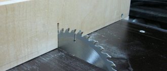
- Fixing the grinding wheel in the chuck expands the processing capabilities.
For your information! To create a high-quality milling machine for metal with your own hands, you need to use other design solutions.
Preparatory stage: design and drawings
At the preparatory stage, it is important to understand what components the future metal lathe will consist of. Based on this, suitable units and parts are selected from available materials. It is important to consider what specific tasks the mechanism will be focused on and what it will be used for.
In principle, the installation should consist of the following elements:
- Electric motor with transmission to the drive mechanism. Working units from old washing machines are often chosen. Usually the power is selected in the range of 1000-1500 W. This is enough for household work.
- Connecting parts (metal corners, bolts).
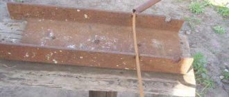
- Housing and metal base (pipe, channel).
- Running gear – handle for longitudinal movement, bearings.
- Supporting part (frame structure).
- Thrust mechanism with cutters.
- The tailstock and the front headstock – ideally, can be taken from another machine.
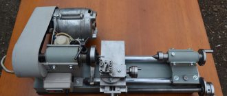
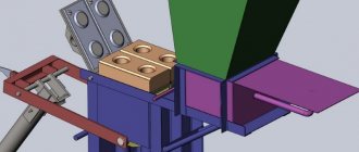
The diagram of the finished device is shown in the photo.
When all the parts are available, you can draw up a schematic drawing of the product. You can take the following drawings as a basis.
The assembled lathe, its main elements can be seen here.
NOTE. It is best to make a metal lathe with your own hands from metal products (pipes, angles, etc.). Any wooden structure is short-lived, and working with the part will be much more difficult.
Making a bed: step-by-step instructions and video
Further actions consist of manufacturing the support unit (frame), installing the working equipment, connecting it to the electric motor and direct commissioning. The sequence of actions is as follows:
- First you need to make a frame, which can be cut from steel pipes (profiles) in accordance with the dimensions in the drawings. All joints must be made only at right angles, so you can check the correctness of the connection using a regular square. The bed is made of guides. which can be used as long shafts.
- The side posts of the frame should be given special attention, since they are load-bearing elements. Consequently, the immobility of the entire structure largely depends on them. It is best to make the stands on a professional lathe.
- Next, you need to assemble the entire support installation: the side elements go along the edges, between them there are 2 guides. Bushings are mounted on the guides at a certain interval, as shown in the photo.
- Next, the bushings are fixed, with the help of which the tailstock and tool holder will be attached. In this case, it is better to make sure that the bushings are of different sizes, since the movement of the mechanism in this case will be greater.
- The surfaces for mounting the caliper are made of ordinary steel sheets. It is important that they are free from defects and even. The optimal sheet thickness is within a centimeter.
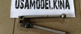
- Next, the lead screw is installed. You can make a carving on a metal stick, but there are simpler options - for example, use the leg from an old swivel chair
- When installing the screw, it is important to ensure that the side posts are equipped with bushings. A steering wheel is attached to the propeller itself to allow rotation, as well as a vernier.
- After this, the surface is mounted on which the headstock will then be installed.
NOTE. The holes on these sheets are also made on a professional machine. They need to be made with particular precision, since even small errors will not allow the device to function normally - the working parts will periodically get stuck.
After this, the frame is completely assembled. It is important to take into account that all elements are tightly connected - the slightest slack is unacceptable, since during operation vibration swings will increase the fragility of the mechanism and can lead to damage.
Visual instructions for installing the frame are in this video.
Metal equipment
Assembly nuances
How to make a metal lathe? Prepare:
- profile steel pipes;
- corners;
- asynchronous type electric motor;
- drive belt;
- fasteners;
- shock-absorbing struts;
- steel sheet;
- quill;
- rolling bearings;
- pulleys of different diameters;
- drive shaft;
- steel plate (thickness 8 mm);
- spindle.
Equipment and tools you will need:
- welding;
- Bulgarian;
- grinding machine;
- drill;
- spanners.
Here's how to make your own metal lathe:
- Make a frame.
- Make side posts for the bed.
- Assemble the guides with the posts by installing spacer bushings between the side support parts.
- Attach bushings to secure the tailstock and tool holder.
- Make platforms for installing the quill and caliper.
- Install the lead screw. Attach the vernier and the steering wheel to it.
- Install the headstock mounting platform.
- Assemble the headstock and tailstock.
- Install them on the machine, checking the alignment.
- Assemble the caliper and make a tool holder. Install these elements in their places.
- Make an engine subframe.
- Install and connect the motor. The assembly of the machine is completed. All that remains is to paint it and you can start working.
Assembling the mechanism with your own hands: step-by-step instructions and video
Further work is aimed at installing the mechanism itself and fixing it on the working surface. The algorithm is as follows:
- If it is not possible to take a headstock from an old machine, you can also make it yourself. To do this, take the shaft and install it on the support using bolts.
- Similarly with the tailstock: if it is not ready-made, it can be made using a screw, profile and bushing. A handle from any mechanism is also selected and mounted into a single mechanism.
- The next stage is to assemble the caliper, similar to the technology for assembling the frame.
- The tool holder, which is manufactured next in line, is based on a regular plate, which should preferably be at least 10 mm thick. Fastening to the caliper using bolts.
- The subframe can be welded from profile pipes. Its dimensions must exactly match the finished product, since otherwise it will be quite difficult to change the position of the belt.
- The final stage is to install an electric motor with a belt drive.
Video: DIY mini lathe. Headstock
It is important to first do the first start at idle speed, and then check the operation of the entire device on a rough metal part.
The main components of a lathe
A unit such as a lathe, regardless of the model, is composed of similar structural elements, which mainly determine all the capabilities of the device.
Name of the main components of the screw-cutting lathe design:
- Bed - this element of the turning device serves as nothing more than one of the main supports for both headstocks and is a platform for moving the support and tailstock. All elements of the device are attached to it. The bed consists of two longitudinal walls, which are connected by transverse ribs for reliability and strength. The headstock of the lathe is fixed to the left side of the bed, the opposite side is where the tailstock is located.
- The headstock holds and rotates the workpiece along its own axis. In the inner part of this element of the lathe there is a spindle that rotates at different frequencies in rolling bearings and thereby transmits the rotation of the workpiece. The outer sides of both walls of the headstock are equipped with gearbox handles, which are switches for the number and speed of spindle revolutions. Instructions for the correct switching of these handbrake in order to set the required number of revolutions are located in the form of a metal plate on the outside of the walls of the headstock.
- Tailstock – supports the remainder of the element during processing. Additionally, it is used to install other working tools.
- Caliper - moves the cutting device in all directions to the axis of the turning device.
- Feed box - the design of almost all lathes is characterized by this element, which rotates the drive shaft and lead screw and changes the number of their revolutions around its axis. There are a large number of feedbox systems.
- Apron - used to change the movements of the drive shaft.
- On this device, it is strictly forbidden to simultaneously turn on the feed mechanism from the lead shaft together with the closure of the uterine nut on the lead screw. This action in almost all cases leads to breakdown of the elements of the turning device. To prevent this, there is a special mechanism in the lathe that completely blocks the entire device.
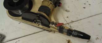
Lathe from a drill: assembly algorithm
To use the device in a city apartment, it is quite possible to create a homemade metal lathe from an ordinary drill in a few hours. It will serve both as an engine and a rotating mechanism. The design is not so powerful, but it is quite suitable for performing small tasks.
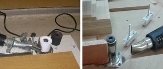
It is advisable to attach the drill to a metal structure - an old stand is ideal.
The manufacturing algorithm is as follows:
- First, as always, the frame is made. Moreover, if you have a reliable workbench with a smooth surface, then it can serve as a support, and then the bed will not be needed.
- Then the wooden bases of the structure are created or a ready-made metal stand is selected. It is important to securely fasten the drill head to the base. This can be done using a regular clamp.
- The emphasis on the other side can be made using bars of the appropriate size. They are fixed to the surface with self-tapping screws. All other assembly stages do not differ fundamentally from conventional devices.
Video: do-it-yourself lathe from a drill
The installation can also handle wooden products - with its help you can apply simple relief carvings to a wooden workpiece, as shown in the video.
HELPFUL ADVICE. Working on a drill lathe is not limited to just cutting parts and sharpening. You can install a copier on it, with which you can create perfectly similar parts at home in a matter of minutes.
Mini-machine: manufacturing video
Often, for household purposes, you need a small homemade metal lathe - here is a video with clear step-by-step instructions for making it.
Safety precautions
Compliance with certain rules when working on a machine is mandatory, especially if we are talking about a product made by hand.
Preparatory stage
Immediately after assembly, you should run the machine at idle speed for a few minutes and listen to the sounds of the engine: they should be uniform, without extraneous noise. Preparation for work consists of the following steps:
- Appropriate clothing is worn, all buttons are fastened and protruding parts are removed.
- Before starting work, the workplace should be in complete order so that only the necessary tools are on it - then you can consistently implement the entire plan without unnecessary fuss and waste of energy.
- Before each session, the homemade machine must be checked for the integrity of all parts and the reliability of their connections.
- It is also important to take care of sufficient lighting of the working surface and the correct location of the source so that your own shadow does not interfere with your work.
Safe work rules
During work, you must adhere to the following rules:
- Removal of parts, as well as cleaning and lubrication of the working mechanism is not carried out during operation.
- When processing a part, you need to be on the correct side and at a safe distance from the installation itself.
- Do not pass any objects or place your hands over the operating mechanism.
- If you are working on cutting a part, then the part being cut cannot be supported by hand - it is unknown in which direction it will move at any given time.
- It is unacceptable to lean even on stationary parts of the machine or lean on the working surface.
- All chips from parts are carefully removed after each working session.
A visual illustration is presented in the diagram.
A visual technology for working on a lathe for hand-made metal is presented in the video.
Features of lathe care
Caring for the mechanism is an essential condition for its long-term, trouble-free operation. Several rules must be followed:
- All waste that falls on the working surface of the device during operation must be removed in a timely manner.
- To ensure even distribution of oil along the guides, you need to move the carriage 7-8 times back and forth.
- All connections need to be tightened periodically, since constant vibration during operation gradually weakens them.
- It is important to ensure that the belt tension is always uniform - either too tight or too loose a tension is unacceptable.
- All moving parts are periodically lubricated with ordinary machine oil. In this case, the bearings are lubricated especially carefully - they experience special friction during operation.
NOTE. Lubricant should not get on the drive belts, since in this case friction is greatly reduced, the belt slides along the surface of the pulley, as a result of which the tension weakens.
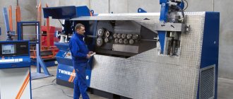
Professional metal lathes
If you need a professional tool for large volumes of complex work, you should understand what types of metal lathes exist.
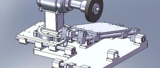
Machine diagram
The schematic diagram of the device is shown in the figure.
Types of machines
Depending on their purpose and features of the device, there are several types of metal lathes:
- Universal ones are designed to perform basic metal work:
- drilling;
- milling;
- turning.
This is the most popular type of device - with their help you can process parts outside and inside, work with flat, conical and cylindrical surfaces. You can carry out complex work on cutting precise threads, processing the ends of parts and drilling holes of almost any diameter.
- Pipe cutting devices are designed for various types of processing of pipes and their connections. They are mainly used in the mining industry and geological exploration.
- Computer numerical control (CNC) lathes are a separate class of modern machine tools that are used in almost all large industrial facilities. Using electronic settings, you can achieve high cutting accuracy and manufacture parts of any degree of complexity. Moreover, all processes are fully automated, which eliminates the human factor.
Depending on the location of the bed, there are the following types of machines:
- Sloping (at angles from 30 to 60 degrees). In this case, all the chips are poured down a chute into a special waste container, making the production process fully automated.
- With a horizontal frame - these devices are equipped with a mandatory casing that prevents waste from scattering during operation.
Types of work on a lathe
Depending on the characteristics of the workpiece feed, as well as on the specific type of metalworking, the following types of work on a lathe are distinguished:
- Turning with manual or automatic feed.
- Cone turning.
- Thread cutting.
- Drilling holes.
Turning with manual or automatic feed
In this case, it is important to set the top of the cutting part so that it is slightly below the axis with the workpiece. If this cannot be done, then it is better to install another tool or grind the part.
Often, when carrying out such work, the tailstock is not needed - then it can simply be removed
NOTE. If it is not possible to ensure reliable fixation of the workpiece in the chuck, you can use a steady rest.
Many models provide the ability to automatically feed the workpiece. In this case, the cutting part should be located to the right of the workpiece.
While working, it is better to always keep your left hand free so that you can immediately press the emergency shutdown if the workpiece strays from the desired direction.
Taper turning
The sequence of actions is as follows:
- The part is secured with a spindle and tailstock.
- If possible. then the speed of the mechanism is adjusted on the machine. It is selected depending on the softness of the material, which can be determined in advance from the reference book. If this is not possible, it can be established experimentally.
- Next comes roughing, followed by finishing.
- If it is necessary to make a so-called Morse cone, it is necessary to shift the centers so that the cone is located at the desired angle, as shown in the figure.
Features of the technology for turning a cone on a universal machine are shown in the video.
Threading
On lathes you can make internal or external threads on a workpiece. Threads are applied to both cylindrical and conical products. There are three types of profiles:
- at right angles;
- at an acute angle;
- trapezoidal.
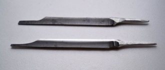
Technologically, the process is performed using a sharp tip of the cutter. The cutter is attached to the support and moves with it, leaving marks on the metal product at a certain interval.
Cutters can be either solid or prefabricated with fasteners. Cutters with soldered plates are also manufactured - they are especially durable, since the plates are made of durable alloys (brass).
Drilling holes
For proper drilling, it is important to prepare the end of the workpiece especially well. It is trimmed to ensure that the surface is as smooth as possible. You also need to make a slight recess at the end so that the work can be done exactly in the intended place. The recess can be made using a drill or cutter.
The size of the holes is adjusted by installing the appropriate drill. If the hole is made smaller, you can drill it out - that is, obtain a larger hole using a wider drill.
Wood cutting machine
Manufacturing
How to make a wood lathe? It's not as difficult as it might seem. You will need:
- drill;
- set of drills and files;
- Bulgarian;
- welding;
- channel;
- corner with thick walls;
- two sections of pipes of different sizes;
- steel strips - 2 and 4 cm;
- fastening elements;
- drive belt.
In the video on how to make a lathe, you can see that the sequence of actions will be as follows:
- We draw up a detailed drawing of the future device.
- We make the tailstock from the chuck and the front part of an old electric drill.
- Let's create a stand. It is mounted on the frame of the unit so that in the future its components can be moved longitudinally along the axis.
- We make the frame from channels.
- We install the headstock, having previously installed a thick plywood sheet as a base.
- We mount the drive on a special plate.
- We install a caliper made from two pipes of different diameters.
- We place a handicraft on it.
- We install a protective sheet of transparent plastic and a lamp.
- We secure the working tools and ground the installation.