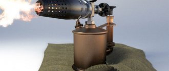
Repairing blowtorches, which are widely used in everyday life, can be done on your own. The device is designed for soldering metal parts; it is also used to remove paint and varnish coatings from metal surfaces. Only a working blowtorch should be used, so the device should always be maintained in working order. If a sudden breakdown occurs, you can quickly repair the lamp yourself and continue working.
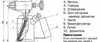
Blowtorch device.
The most common malfunctions and causes of failure
The most common malfunctions of a blowtorch are as follows:
- the pressure required for normal operation is absent or rapidly decreasing in the housing;
- there is no flame due to the fact that the fuel stream from the injector does not meet the required parameters;
- fuel leaks through joints and seals;
- Instead of spraying, a stream flows out of the nozzle.
Some problems can be fixed if you have the necessary tools at hand. Typically, repair work consists of cleaning individual components.
Sometimes the breakdown is so serious that it is impossible to repair the tool without the spare parts used for the blowtorch. Fortunately, you can find many repair kits in hardware stores and on specialized websites on the Internet.
The reason for the lack of pressure in the lamp may be a faulty pump. It can be replaced or repaired with your own hands. A rapid decrease in pressure occurs if the threaded connections, service and safety valves are leaking.
The problem is solved by replacing the gaskets, cleaning the surfaces of the covers and valves in contact with the body.
There is no burner flame if the fuel stream coming from the nozzle is very weak or intermittent. This can occur due to contaminants that have entered the lamp with low-quality fuel. In this case, it is necessary to clean all the channels and the jet with suitable tools and rinse the lamp with clean gasoline.
Fuel leaks through the seals of the control valve if the stuffing box, which is the sealing gasket between the body and the valve, has lost its properties. Repairing the malfunction involves disassembling the tap and replacing the stuffing box.
If fuel streams out of the burner, the reason is most likely that the nozzle opening is not correct. Before this, you need to make sure that the instrument is really warmed up. If problems of this kind recur during warm-up, the burner nozzle must be replaced.
If there are problems with the supply of fuel and air mass
In this case, prepare a straight-head screwdriver, pliers, a needle and thin wire. A fuel supply problem is detected by the appearance of foam and its seepage through the base of the nozzle. Most likely the jet is clogged.
Repair work involves the following sequence of manipulations:
- If there is a visible small gap, carefully insert the needle into the calibration recess and clean the fuel tube with it.
- If a positive result is not expected, the nozzle is removed.
- The wire is placed in the hole of the fuel pipe.
- Next, unscrew the valve.
- Pour gasoline into the channel. Perform the manipulation carefully and slowly.
- Assemble the structure into a single whole, put the jet in place.
- If flames appear from under the stem, extinguish the fire.
- Remove the valve handle and replace the worn stuffing box in the intake needle with a new one.
Essential repair tool
The following tools may be required for repairs:
- adjustable wrench;
- screwdrivers;
- pliers;
- small brush;
- sewing needle or thin steel wire.
Materials you may need include stuffing box, steel washers and nuts, gasoline or kerosene.
You will need to disassemble the tool and its components with a wrench and screwdrivers to provide access to the faulty part. You will need pliers if you have to hold the needle to clean the nozzle hole without disassembling the burner. In addition, it is convenient to use pliers to hold any screws from turning during assembly and disassembly. A brush is necessary to wash away contaminants that have entered the body and burner. It is advisable that the brush be long with hard natural bristles.
Pump repair
The blowtorch pump consists of a piston enclosed in a metal housing and a spool, which is installed at the end of the piston tube and operates on the principle of a check valve.
It lets air into the body and does not let it back out. At the end of the piston there is a leather cuff that pushes air when moving inside the lamp, and folds up to let air through when moving in the opposite direction.
This piece is simply a circle of leather sandwiched between two steel washers of different diameters. The upper washer is almost equal in diameter to the diameter of the cylinder, and the lower one is several millimeters smaller. Thanks to this, the cuff is able to pump air, folding only in one direction when necessary. To increase the service life of the cuff from repair to repair, it must be lubricated occasionally with thick lubricant.
Most often, the spool or cuff is faulty. Repairing a blowtorch pump will involve replacing them with serviceable ones. The best option for repairs would be to take working spare parts from a non-working old blowtorch, if possible. If you cannot find them, you will have to buy these parts.
The cuff, however, can be cut from a suitable piece of leather or from any suitable cuff for another pump.
A little about making leather cuffs for Primus stoves
Posted by Manuel · 04/10/2016 08:32
4,634 views
Often in old Primus stoves, due to their venerable age, the leather pump cuff is one of the parts susceptible to destruction.
A few words about how to make a new knee cuff. Dimensions are given for the Tula Primus pump with an internal sleeve diameter of 18 mm.
1. Cut out a circle the size of a two-ruble coin from leatherette, or preferably from genuine leather 2 mm thick. The PVC coating must be removed with sandpaper.
2. Use a punch to punch a hole with a diameter of 5 mm in the center.
3. We clamp the resulting “washer” on the M5 pin, with the “shaggy” side inside the molded cuff. It is better to take an M5 washer with a “shaggy” side with a diameter of 9.10 mm.
4. Dip the pin together with the workpiece into melted paraffin and leave it there for 15-20 seconds for impregnation. You should not wait longer than this time, because the leatherette blank becomes rigid and inconvenient for further molding.
5. First molding on a die with an internal diameter of 20 mm.
6. Second molding on a die from a tube with an internal diameter of 17.5 mm. It is necessary to keep the workpiece in the tube until it cools completely. If there is no tube, you can use the pump sleeve as a mandrel, after removing the burrs.
7. Holding the workpiece by the pin, use a sharp knife to trim the uneven edges along the cut of the tube.
9. Using a punch with a diameter of 8.9 mm, punch a hole in the workpiece.
10. That's it! The cuff is ready!
The pump is assembled in the following order:
1. The handle is screwed onto the rod and the pump cover is put on.
2. At the place where the transition from a diameter of 6 mm to a diameter of 5 mm begins, a little cotton soaked in oil is wound. thread This is necessary to prevent air leakage.
3. The pump washer is put on; the side facing the cuff should have a smooth, burr-free surface. This is also necessary to prevent air leakage.
4. Next, a piece of brass tube is put on.
5. A cuff is placed on the brass tube. The cuff should sit loosely on the brass tube, the gap is 0.3. 0.5 mm. This is necessary for active filling of the sleeve with air during the reverse stroke of the rod.
6. An M5 nut with “flat spots” is screwed onto the thread of the rod.
7. The nut with “balts” is locked with a regular nut.
8. The cuff and rod are lubricated with semi-liquid oil. I used a compressor.
9. The assembled structure is inserted into a lightly lubricated sleeve. A test pumping is carried out.
Cleaning the jet
The jet, as already mentioned above, can either become clogged with dirt from low-quality fuel, or carbon deposits from its combustion. In both cases, cleaning can correct the situation. If you need to use the lamp very urgently, you can try to clean the nozzle with a needle held in pliers. But in this case, contaminants will get inside. Immediately after completing the work, it is necessary to disassemble and clean the entire blowtorch.
If there is no hurry, it is better to unscrew the jet from the burner and try to blow it with compressed air from a compressor or from a special can. Only if this method does not produce results, you can carefully use mechanical cleaning during repairs.
After cleaning the nozzle, it must be washed in gasoline and dried before installing it in the burner.
What's inside?
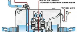
If we take on the repair of the “fire-breathing dragon,” we should figure out what’s inside it:
- Fuel tank 2 is needed not only for fuel, but also for compressed air above it. The container has a filling hole with a lid 11.
- The fuel is supplied to the mixing pipe 7 through the mixer channel 5, and the flame intensity is adjusted using valve 10.
- Fuel vapor is supplied through nozzle 8.
- Pump 12 allows you to create working pressure in the container. It makes it possible to increase blood pressure.
Handling old lamps
Old blowtorches that have not been used for a long time should first be inspected from the outside. During inspection, you need to check how easily all the valves and the tank lid open. The adjustment valve should turn easily.
After this, you need to check the housing for leaks. To do this, use a pump to pump air into a lamp that is not filled with fuel. Then, using a brush, apply a thick soap solution to all threaded connections and the faucet. You need to check it closed and open.
If all connections are tight and the pump is properly creating pressure in the housing, the tap performs its functions by opening and closing the burner, the lamp can be refilled and started.
Device
A gasoline blowtorch consists of the following components:
- A burner designed to use a specific type of fuel. For example, a gas blowtorch will have a different burner design than a device using liquid fuel.
- Fuel tank.
- Systems for supplying the combustible mixture to the burner.
- Manual fuel supercharger (pump).
- Shut-off and control device.
- Check valve (not available in all designs).
- Holding handle.