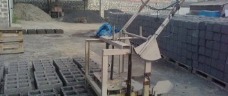
In this article we talk about how building a CNC milling machine with your own hands is a feasible task. The entire creation process is described in detail: from design to use of the machine.
In the first case, home-made parts made on a lathe were added to the purchased components; in the second project, the author made do with ready-made parts; the third was a bonus, the manufacture of a functional table for the machine, combined with shelves for storing materials and tools.
CNC table
For dessert, not a machine, but a useful and interesting homemade product for a machine, namely, a durable and roomy frame with shelves. If you don't already have a CNC machine, you can build one early and use it as a workbench.
Evan and Katelyn, owners of EvanAndKatelyn.com, updated their CNC machine table to add functionality and space.
The product was assembled entirely using screw connections, without the use of glue, in order to maintain the possibility of easy alteration and upgrade.
Tools and components used:
- Stop button;
- Roller lock;
- Countersink and bits;
- Drill;
- Electric screwdriver;
- Saw;
- X-Carve machine;
- Quarter-inch carbide-coated end mill;
- Quarter Inch Carbide 4 Flute Ball End Mill;
- Hearing protection.
Step 1: Preparation
Step one is to remove everything from the old table, starting with the machine and ending with a bunch of other things lying there, and partially disassemble it. Everything was completely dismantled except for two large shelves 120 x 120 cm, which were strengthened and made the basis of a new table.
Step 2: Strengthen the Shelves
Corner brackets were used on the four inside corners and L-shaped brackets were used along the crossbeam that runs along the bottom side.
In the photo below: comparison of a reinforced shelf with an unfinished one.
Step 3: Trim off the excess
Originally there were 4 racks rising above the top of the table because an additional shelf was planned above the machine. This idea was rejected, deciding to leave two out of four racks.
They were reinforced with corner brackets.
Small wooden stands were added to secure the shelves.
They placed a shelf on top of them and reinforced it with even more brackets.
Strength test.
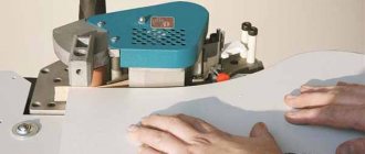
Step 4: Pegboard - Toolbar
The updated piece of furniture needed to add as much storage space as possible, and one of the details that expanded its capabilities was a perforated panel in the holes of which tool holders are attached. The corners were cut out on the panel with a jigsaw.
See the video for more details. Then they simply screwed it on.
Step 5: Bottom Shelves
For storage in the lower part it was necessary to leave as much space as possible, because... This is where the table saw and drum sander are stored. A lot of space was also needed to store materials, so it was decided to add a shelf, but make it easily removable. Wooden blocks and a sheet of plywood prepared for the legs came in handy.
The legs were attached to the plywood sheet with corner brackets, and the resulting shelf was inserted into the lower part. It's easy to remove when full-height storage is needed again.
Step 6: Top Shelves
The old bed had a top shelf for the computer that operated the machine and for various small items. There was still space left, and they decided to make another one under this shelf. It also helped cover the outlets and wiring for the machine.
The top shelf was placed on the ends of the racks and screwed.
In the second shelf, we used a jigsaw to cut out the corners for the legs.
And they also secured it with corners.
Step 7: Finishing Touches
Trays were added to the pegboard for storing screwdriver bits and other small items.
A sign with the inscription “Call me” was screwed onto the end, which will later be replaced by a name invented by subscribers on YouTube.
Finally, everything that was in its predecessor was returned to the table.
All photographs belong to the authors of the projects.
X
Let's start with something simple - with the base table. An elementary geometric calculation shows that with a stroke along X equal to 1000 mm, the length of the table should be 1300 mm. At least that's how it worked out for me. When the Y stroke is greater than 300 mm, the table width must be at least 460 mm.
Having studied the assortment of standard pressed rectangular pipes (boxes) made of aluminum alloy AD31 (the industry, unfortunately, does not produce others), we select a box 80x40x4 mm. We cut several beams from it (1300 mm - 2 pieces and 460 mm - 4 pieces). We will also need two channels 50x30x4 with a length of 1300 mm. The SBS15SL ball guides, which I decided to use, fit perfectly into them. For legs we use matching round sofa legs purchased at the OBI store. We drill holes in all this, paint some things if possible, and assemble the base frame.
It turned out quite strong. Under load, the channels in which the rails will be laid bend slightly, but that’s okay; if we install a table top, it will be a completely different matter; the base will acquire exceptional “oakiness” in terms of strength and rigidity.
We screw the rails.
They are located under the table and, as you can see, are relatively well protected from dust and shavings. Despite the fact that SBS ball blocks are equipped with scrapers, it is never harmful to provide additional (passive) protection for the rails and blocks from direct contact with chips.
We screw the platforms on which the portal will subsequently be placed to the ball blocks. These platforms are simply rectangular plates made of D16T alloy with holes for attaching the portal and bracket for the stepper motor.
We’ll talk about the stepper motor bracket and the timing belt wiring in general separately.
Timing belt wiring
Yes, stepper motors for moving the portal along the X axis will be mounted on the portal itself! For some reason, when they talk about a toothed belt drive, the brain pictures a belt in the form of a ring with a motor mounted on a frame, and the belt tension is organized on a portal or carriage. This can be done, but is it the best way? Not sure. We'll go the other way. Let's make a pseudo gear rack out of the belt.
We secure the ends of the belt to the frame. We will fix one clamping bar rigidly, and the other will be able to move to tension the belt within the distance between adjacent teeth, i.e. within 5 mm. The gear wheel, as usual, is mounted on the motor shaft. The rollers are mounted on the same bracket as the motor. In general, everything is obvious - the motor rotates and moves itself.
Why is this method better than a ring belt? Yes, at least because the belt consumption is half as much, it is easier to tension, and there is a saving on gears, which are expensive and must be purchased together with the belt. Rollers with axles can be selected ready-made. In general, there are advantages to this solution. What about the cons? Don't know…. Carry cables from motors behind the portal? So, carrying them from the Y and Z axes anyway, plus or minus a few wires, is not important. Will the weight of the portal increase? Will increase. And this is probably the only negative worth talking about. The issue price is 1.5...2 kg (motor weight) and/or 100 US dollars (long belt and additional gears). I chose saving money over weight. With such dimensions of the portal, saving two kilograms of its mass does not provide a significant gain. After all, when using racks, the motors sit on the carriages.
The belt must have a relatively fine tooth. I chose a belt that was dear to my heart from the tail boom of the Raptor 50 helicopter model. It has a tooth pitch of 5 mm. The gear wheel is also from this helicopter. Its diameter (along the center line of the teeth) is 14 mm. This means that when the engine is turned on in half-step mode (400 steps per revolution), the movement of the carriage by one step will be 3.14 * 16/400 = 0.11 mm. This is more than intended. In a microstep (1:6), the movement per step is 0.042 mm. Just what you need. And although a “non-stretching” belt still stretches a little, there is no accumulated error in the belt, which is always present in the lead screw. As a result, I think we will achieve a milling accuracy of 0.1 mm over a length of 1000 mm. At least for balsa and four-millimeter plywood.
As for the stepper motor bracket, as you can see, it is a simple plate with holes. Nothing special, we cut it out in the same way as the base. So far we have not gone beyond the scope of a hacksaw, drill and file. We will continue in the same spirit.
We install the whole thing on the frame and check how it drives. Drives well!
Actually, it's almost all with a frame. All that remains is to “comb it”, give the product a “marketable appearance” and install the countertop.
Marketable condition
“Made in home” doesn’t have to be lopsided, clumsy and sloppy. I am depressed by the engines mounted on ugly “chicken legs” and sticking out in all directions, bundles of untidy wires, controllers turned inside out and similar “charms” of homemade structures. Everything would be fine, in the end, everyone does as best they can, until the author of yet another such monster begins to seriously talk about mass production of his brainchild for sale, justifying the unsightly appearance of the machine by the fact that it is, they say, a prototype: “We’ll fix it here, we’ll redo it there.” , we’ll hang the covers, paint everything, and it won’t be a machine, but a piece of candy.” Will not be! If the author cannot do the right thing for himself, his beloved, and he is not ashamed to advertise his unfinished “product,” then he will make a mistake for the buyer. Tested more than once. But this is true, by the way...
Let's lay a couple of dead channels in which loops of cables from motors and limit switches will be placed. If the controller is large and does not fit into the under-desk space, then we will make brackets for the output connectors. And finally, we will install plugs on the ends of the supporting profiles so that dirt does not accumulate in them.
The labor costs for these seemingly optional activities pay off with interest.
Tabletop
The machine is planned mainly for sawing balsa, plywood, plastics, so the tabletop can be made of a laminated panel for kitchen furniture with a thickness of 40 mm, i.e. the same thickness as aluminum boxes. The tabletop is attached to two supporting beams of the frame. The channels in which the rails are laid should also be attached to the tabletop with self-tapping screws. Overall, the structure is smooth, strong and rigid. You can calmly stand on the resulting base of the machine and walk around it on foot - nothing will happen.
Some “advanced” specialists may like a stacked tabletop made of machine-made aluminum profile. Please, nothing fundamentally will change. However, a machine on toothed belts can only saw what it is designed for, namely plywood, plastics and thin aluminum, and nothing more, so tightening the tabletop is pointless.
Features of choosing a router design
The capabilities of modern CNC equipment are enormous. But no machine is universal. Each model has its own characteristics and preferred area of application. Before choosing a specific design, you should clearly determine what the machine will be used for. An attempt to combine everything in one will lead to large material and physical costs, without guaranteeing results.
Today, there are two directions in the design of desktop routers. The first, the simplest, is focused on processing wood, plastic and other soft workpieces. Such machines do not place high demands on structural materials and are simple and low in cost. They are available for self-production, without the use of additional equipment. Metal products on such devices are usually not milled. In rare cases, only soft non-ferrous metals are sharpened at low feed rates.
The second direction of milling cutters is focused on working with metal workpieces. These machines have a significant mass and consist of parts that can only be completed using a serious machine park.
The second most important parameter of the machine is the dimensions of the processed parts. Beginners immediately want a large field where they can do whatever they want
But the larger the machine, the more technical problems will have to be solved during its design. And its cost will not be the most optimal. If there are no specific tasks for a large machine, then it is recommended in the first project to limit the processing field to the size of a standard A4 paper sheet. The maximum you can choose is A3.
XYZ
Set Z to Y.
We install the side walls of the portal and the terminal box for cables.
We install the portal on the frame.
That's all. The machine turned out to be comfortable, slender, I would even say lean, nothing sticks out, there is good access to the working field from all sides, no casings that cover anything, no “caterpillars” for wires, all wires are hidden. By the way, in my copy the controller is also hidden under the table; only the power cord and the LPT port cable from the computer are suitable for the machine.
Even if you sawed everything crookedly and didn’t drill the holes very accurately, you can still modify the machine, bring it to mind and make it work normally. Because in this design everything is determined by the obviously accurate purchased guides and the acceptable geometric accuracy of the extruded profiles (parallelism and perpendicularity of the edges). Here, in principle, there are no difficult fits and strict tolerances on linear dimensions. However, it goes without saying that the more accurately you make the parts, the better for both the machine and the products that you will cut on it.
Preparing for work
How to make a coordinate table with your own hands
Before assembly, we study the structure in parts. If there is nothing to choose from, then we buy the necessary materials for one-by-one assembly.
What materials should I use?
It is not forbidden to assemble a structure with your own hands from available materials. Everything comes into play:
- Plywood of any thickness.
- Boards or shields made from them. Any bars.
- Chipboard, fibreboard.
- Rolled steel and aluminum.
- Pipe rolling.
Required components
It is necessary to purchase additional components if a CNC milling table is planned. But a classic stationary machine is not difficult to make from:
- Any hand router.
- Drills.
Tools for work
For work we prepare:
- Wood glue.
- Nuts, screws and bolts of the required size.
- Cover material (MDF or plywood).
- Power tools (jigsaw, miter saw, etc.).
- Sandpaper.
- Marking tool.
How to make a mounting plate
How to make a carpentry workbench with your own hands?
The mounting plate must be wider than the diameter of the cutter if you plan to work with several cutting attachments. It is more profitable or cheaper to form this element from 20 mm birch plywood.
But it is more practical to work on a homemade machine with cast polycarbonate as a mounting plate. The essence of the work is this:
- Remove the soleplate from the power tool, having first placed the mounting plate face up.
- Temporarily connect the plate and sole using double-sided tape.
- Select drills to match the diameter of the factory fasteners and drill the correct holes for fastening on the plate.
- Next, connect the homemade plate with the router and place it on the table for adjustment.
- An 8 mm drill is placed in the collet and the motor is lowered. You need to touch the plate with the drill and mark the center.
- Next, follow the mark to make a hole of the required diameter.
Zet
The Z stroke is planned to be 90 mm. Why 90? Because 90 is enough for me, but you can do 150 mm. This is not important.
The Z carriage and everything connected with it is the most busy and labor-intensive part of our machine. This is understandable; the drive along the Z axis cannot be done on a belt. Each time the machine is turned off, under the influence of its own weight and the weight of the spindle, the carriage will move down and lose “0”. In addition, a significant holding torque is required from the motor, which must compensate not only for the milling force, but also for the weight of the spindle. Only a screw with a pitch of no more than 5 mm (preferably 3 mm) saves the situation. So, here are the parts that need to be made.
Lead screw
Let's start with the screw. I have already written in detail about lead screws and nuts in the article “Mechanics of a homemade CNC machine”, I will not repeat myself. BUT. Is it really necessary in this case to have a lead screw with a nut on the Z axis, made according to all the rules of precision mechanics? Hardly. The machine is designed for flat milling, in fact, it’s just a CNC jigsaw - lower the cutter to the required depth and start cutting. A rolled screw will do here. Yes, why not a rolled, simple screw with a metric thread will do! And a nylon nut will do! It’s another matter if you plan to 3D milling, for example, bas-reliefs and medals..., but such a task does not fit well with the belt drive of the remaining axes. So, ANY screw can be used. Any one, any one, but I used a Tr12x2 rolled screw and a bronze nut with backlash compensation. Because Today I just have a jigsaw, but tomorrow I might want to put screws on all the axes. The design allows.
By the way, the lead screw, the adapter sleeve for the motor and the bearing support rings are the only parts for which we will need a lathe. Even if you bought a threaded rod from the market, the ends of such a screw need to be cut.
The design of the lead screw bearing assembly is described in the above-mentioned article. It turned out to be successful, so we’ll do the same thing in the new machine.
It is not necessary to bore the hole in the wall for the bearings to fit; just drill it. The working loads are directed along the axis of the screw, and if the angular contact bearings move slightly in the transverse direction, then it’s okay, this will have virtually no effect on the accuracy of the axis.
Assembly
We install the lead screw inside the channel base, made from a 60x40x5 mm profile, the same as the one we used for the Y carriage. We screw the rails to the ends of the base.
An attentive reader will say: “Aha! The part on which the engine is mounted is milled!!!” Not necessary. It can be made from two flat pieces and screwed together. For example, like this.
We install the corners on ball blocks. The corners are made of profile 50x50x5 mm. This is the only available profile made of D16T alloy.
A panel is placed on the corners in front, which, in fact, is the Z carriage. But before that, we will install a jumper that will connect the corners with the running nut.
At first glance, this detail is unnecessary. The running nut can be fixed directly to the front panel. But in this case, the requirements for the precision of manufacturing parts increase significantly, and the installation of the nut will have to be done blindly. Because We have a machine “in a hurry” and we make it in the kitchen, then in this case such a transition piece may be useful. However, those who are confident in themselves may not install it.
Finishing touch. Install the front panel and spindle bracket.
The bracket can be milled, or maybe just flat. It's up to whoever it is. The Z-axis lead screw turned out to be well protected from direct chips. In general, the Z carriage turned out to be compact, its width is 118 mm. Not a bad result, considering that the main parts are made from standard profiles.
Manufacturing stages
After purchasing all the necessary materials and tools, you can proceed to assembling the table yourself.
Manufacturing of working surface and box
At the beginning of making a vacuum table for CNC, you need to create a working surface with your own hands. To do this, take a pre-prepared sheet of material. Holes are carefully drilled in it, in a checkerboard pattern, using a drill or screwdriver. Later, from the back, the surface will be adjacent to the vacuum pump, which serves to securely fasten the products. To increase the reliability of the structure, partitions are installed. They prevent the table from deforming during use.
Box
The most significant thing here is the height, since the table is designed for a numerically controlled machine. A stable structure is assembled from metal and wooden parts to secure the working surface. The surface above the working area will act as a holder for the heating element. It is desirable that the box be collapsible: this will facilitate further work, setting up equipment or transporting the table in the future.
The desktop should be as stable and reliable as possible. Therefore, it is advisable to avoid short-lived or moving connections in the design. To make it easier to move the tool, you can use adjustable height feet. This will allow you to work on uneven surfaces, providing stability.
A heating element
Vacuum forming of plastic also requires a special table. During operation, the product is exposed to a vacuum field and a heating element, which heats the plastic to the required temperature. To do this, a heating panel is installed above the table. Nichrome thread has proven itself best as a heating element. However, due to the high cost of the material, as well as the difficulty of finding it on the open market, halogen lamps are usually used for self-production.
A sheet of metal is taken as a workpiece. Holes for lamps are also drilled in it, after which the heating elements are secured and the electrical part is installed. All lamps must be connected in parallel. With a more complex design, the electrical part is output to a controller or separate switches to heat certain parts of the work area. The connection is made using soldering and copper wires. To reduce wiring, have a more pleasing appearance, ease of operation and greater wiring reliability, it is recommended to use a printed circuit board or several small circuit boards. The design of the light panel should also be dismountable for maintenance.
Vacuum pump
The most important piece of equipment. Serves to create a vacuum and securely fix the part. It is best to use a specialized vacuum generator with a pressure gauge. If a dedicated vacuum pump is not available, several vacuum fans will do. It is possible to replace them with industrial vacuum cleaners, but in practice their efficiency is lower.
When connecting, it is important to reduce the air flow as much as possible, that is, insulate from the entrance to the working surface. A pressure gauge is needed to measure results: too much vacuum can damage the part, work surface or equipment
With a more complex table design, the heating part regulators and pressure gauge are installed in the control unit.
Control block
The electronic part of the vacuum table is needed to effectively regulate the heating of the working area and create a more stable fixation of parts. There are many options for implementing a control unit; the biggest role here is played by a milling machine and numerical control installed in the working equipment. The most optimal one is selected based on the tasks, budget, and availability of specific elements. For optimal operation, a microcontroller with display and one relay per control unit are required.
Temperature and pressure sensors are used for comfortable operation. The minimum configuration requires one sensor and 2 relays: one to turn the pump on/off, the other to control the heating panel. To delimit the work area, use the clamp and heat only for part of the table, it is necessary to use a larger number of relays and, accordingly, a more efficient controller. Installing a reliable control unit will make work more comfortable and will allow you not to be distracted by pressure gauge readings.