When looking for an idea for a profitable and successful business, it is not necessary that it be original and different from others, because many successful entrepreneurs started with something small, already known, and developed this direction. The modern world offers many options for developing your business. This could be training and education, advertising and provision of services, construction and production, etc. If you decide to start some small production, then the first item in the project, of course, will be equipment.
Operating principle and design
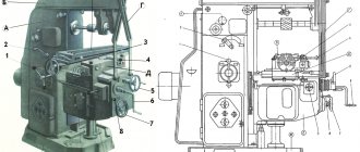
This equipment consists of a mechanical part and an electronic subsystem. The workpiece is processed by a rotating cutter. It is mounted in a chuck on the spindle shaft. Depending on the task, choose the shape and size of the cutter. The spindle motor creates rotational motion.
The CNC controller itself carries out commands to move the workpiece in three coordinate axes, as well as to fix the cutter at the required point for processing the part.
The electronic system consists of the following components:
- controller;
- memory device;
- operator panel;
- display.
The controller, reading the description from the computer, gives commands to the equipment. You can control a desktop CNC milling machine from a personal computer or laptop.
Main characteristics of the equipment
When choosing mini-machines, you need to pay attention to the main characteristics of milling cutters, based on which you should make your choice. The main parameters of this technique include the following:
- Equipment power indicators. To work with metal, it is necessary to select milling cutters with a power of 400 W or more. Installations with a power of 200-400 Watt are intended for working with wood.
- Worktop dimensions. For mini-machines, the worktop can be made with dimensions from 15x35 centimeters to 15x65 centimeters. The choice will depend solely on what workpieces you plan to work with on the unit.
- Spindle stroke and distance to it.
- Milling machine performance and spindle speed.
- Weight and dimensions of the unit.
The functionality and versatility of using such a mini-machine will directly depend on the type of cutter installed. This is a cutting tool that is equipped with sharp and durable teeth.
High-quality cutters are made of heavy-duty materials, and the arrangement of their teeth is such that the teeth are included in the processing not simultaneously, but one by one. Currently, there are various types of cutters that are intended for certain types of work.
- To make grooves, recesses and grooves, base, disk, corner and end mills are used.
- Surface treatment is carried out with cylindrical and end cutting tools.
- For shaped surfaces, use appropriate shaped cutters.
- Modular, disc and finger cutters are designed for machining wheels and making teeth.
By choosing the right cutter to use, it will be possible to ensure the quality of work on the mini-machine; the cutting tool will be reliable, wear-resistant, and the sharp edges of the teeth will not grind off, efficiently processing various parts made of metal and wood.
A miniature milling machine is a versatile and easy-to-use piece of equipment that is used equally well by professionals and ordinary homeowners for domestic purposes. You can choose equipment that will differ in its power, design, purpose and type. The choice should be made based on the intended work on the machine, which will allow you to purchase high-quality equipment that will combine functionality and ease of operation.
Purpose of small-sized milling machines
The equipment has wide functionality and performs the following types of work: boring, drilling, engraving, milling. The machines can be used in almost any manufacturing enterprise. The compact size and light weight allow the use of small-sized machines at home, as well as in small workshops.
Models for processing metal and wood are available for sale. You can also work with plastic and plastic on mini-machines. If you have an engraving head, any patterns and decorations can be applied to workpieces made of wood and metal, which allows you to create decorative products.
Purpose of mini milling cutters
Today on sale you can find universal models that are designed to work with metal, wood and wood, as well as highly specialized mini-machines that can only work with one or another material. The use of powerful motors and a special design of the working head allows the compact equipment to perform various workpiece processing jobs.
Using mini-mills you can perform the following work:
- Drilling.
- Milling.
- Countersinking.
- Engraving.
- Making holes.
Reconfiguring the machines is not particularly difficult, so every homeowner who has never even had experience with such a mini-machine can handle using such a unit.
This equipment is used in car services, in workshops where household appliances are repaired, the machine will be indispensable in a subsidiary farm and will be useful to every summer resident.
The advantages of mini-devices include the following:
- Affordable price level.
- Operation from household power supply.
- Low power consumption.
- Minimum noise level.
- Ease of maintenance of equipment.
- Light weight, compact dimensions.
- Wide range of possibilities for using technology.
Today, many buyers have appreciated the wide possibilities for using metal milling machines, their compact dimensions, affordable cost and ease of operation. There are various models of such equipment on sale, which allows you to choose both relatively simple equipment options and machines that are fully automated and allow you to work with them at a professional level.
Types of mini CNC routers
Depending on the design solutions, all mini-milling machines are divided into 2 types:
- Console. In this solution, the part is attached to the console – a moving element. The console moves along the guides of the frame. All operations are performed by a stationary spindle on which the cutter is attached.
- Consoleless . The table makes longitudinal and transverse movements and the part is fixed to it. The spindle in this solution is movable; it processes the workpiece in different directions, including vertical.
Depending on the model, the spindle can be positioned vertically or horizontally.
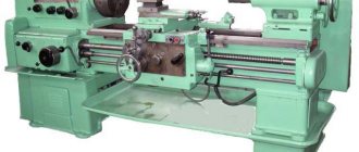
Operating principle of a mini metal milling cutter
mini cnc router
All milling machines, regardless of power and size, operate on the same principle. The part is processed with cutters of different sizes and shapes. The workpiece is placed on the working surface, the cutter is installed in a chuck, which is secured to the spindle. The spindle is the unit that receives movement from the motor and transmits it to the cutter.
According to the position of the operating tool, milling cutters can be vertical or horizontal. Most desktop mini milling cutters are manufactured with a vertical placement of the actuating tool.
Often in mini milling machines the spindle is located on a mobile portal. On CNC machines, the portal moves in three-dimensional space, executing controller commands. The devices are equipped with stepper motors. The electric motor rotates the cutter via direct drive from the cardan shaft. The small device is equipped with a control module with two or more rods.
There are mini modifications with a movable table. It moves in a plane perpendicular to the cutter. At the same time, the cutter makes translational and rotational movements. This is how shaped and flat surfaces are processed.
When working with a cylindrical cutter, the direction of the cutter and the tabletop is in the same direction. Otherwise, the quality of processing is significantly reduced.
Some desktop devices are additionally equipped with an engraver; special clamps are provided for this.
The most primitive model of a mini metal milling cutter consists of an electric motor, drive, rotor and collet. As a rule, the power of such equipment is low and the capabilities are limited. It has a short service life - about 10,000 hours, after which the mechanical components must be replaced. For amateur use this is a perfectly acceptable device.
Popular home models with approximate prices for them
Benchtop CNC routers can be woodworking or metal. For wood processing, non-cantilever units with a small work table are most often used.
Used in carpentry and turning workshops, in furniture production. Metal cutting machines are most often used in automotive workshops and small batch production.
On wood
Among the most popular models of mini woodworking machines:
- CNC 3018. Work table size – 300x180 mm. Performs engraving, cutting, milling, drilling on wood, as well as laser engraving on leather and plastic. Estimated price – 16 thousand rubles.
- Compact machine with replaceable working modules. The machine is made of adonized aluminum, so the design is reliable and durable. The manufacturer set the price at $530.
- Piranha FX. A modular compact machine that can freely perform milling, 3D printing, and engraving. Prices start at $2,500 depending on configuration.
Tabletop woodworking machines, depending on the capabilities and configuration, can be of different price categories. Technical specifications also differ.
For metal
High-quality metal cutting machines with a small working space are also popular among small industries and private entrepreneurs:
- AMAN 2030 200w. Desktop – 300x200x60 mm. Processes the workpiece in three coordinate axes. Spindle up to 8000 rpm. Cost 105 thousand rubles.
- Weiss Machinery WMD16V. Designed for working with ferrous and non-ferrous metals, boring, milling, drilling. Machine weight – 60kg. Cost – 98 thousand rubles.3. JET JUM-X2. Widely versatile tabletop machine. Equipped with a vertical and horizontal spindle. Cost – 120 thousand rubles.
Some types of metal can also be processed by woodworking machines. But for cast iron and steel you need to use more rigid equipment.
Classification of mini milling machines
The main difference between tabletop metal milling machines is the processing accuracy:
- average;
- increased;
- high.
The drawings of the part always indicate tolerances for dimensions and the degree of finishing. According to the type of material processing, all devices can be divided into the following groups:
- vertical console: the executive tool is located vertically, can move in a vertical plane and rotate;
- horizontal cantilever: the executive tool is placed horizontally, fixed at one point, the table top with the part moves;
- universal console: the working surface rotates to the desired angle;
- widely-universal console: in addition to a horizontally mounted actuator, they are equipped with an additional head capable of rotating in two planes;
- longitudinal milling: the working surface moves along rails in the longitudinal direction. The executive bodies and racks move in the vertical direction and across;
- non-console: the executive instrument moves in a vertical plane;
- volumetric: used as copiers and under CNC control;
- carousel, they are also continuously operating: they are equipped with several vertical executive tools that move in a vertical plane, and the round tabletop also rotates;
- keyed: equipped with a vertical spindle that moves planetarily and additionally rotates around its axis. Planetary movement parameters are set.
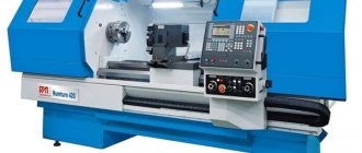
Tabletop mini CNC routers
vertical tabletop mini metal machine
This is high-tech equipment, which is completely controlled by the program through a connection to a computer. Unlike industrial equipment, desktop equipment is never equipped with a control panel. Parts are processed with high speed and precision. The most common designs are equipped with a console on which the workpiece is fixed. During processing, the console moves.
The machine is controlled through the program:
- contour;
- positional;
- multi-circuit;
- combined.
Mini milling and engraving machines
The difference between these machines is the mandatory presence of CNC and low power. Their structure is similar to a conventional desktop router.
They are suitable for engraving work on metal, as well as cutting small products from thin materials (plywood, leather, plastic). Such equipment is used for amateur work and small batches of advertising, souvenirs, and jewelry.
What should you consider when choosing?
When choosing, you need to pay attention to the main technical characteristics of the equipment. You should not take a powerful machine if the intended work process does not require it. This way you can save not only money when purchasing, but also reduce energy costs.
All characteristics must meet the requirements for a specific work process. For some processing options, a spindle with low power is sufficient, and when working with heavy metal and large workpieces, the required power increases.
Mini CNC milling machine is a high-tech equipment that is suitable for small batch production and home use. At the same time, the processing accuracy and reliability of the units is maintained at a high level. The main advantage is compactness and savings in energy costs.
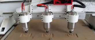
Small CNC milling machine
In this article, a DIYer will tell us how he designed, built, assembled and ran this mini CNC router. The task was to make a (relatively) inexpensive CNC milling machine for home use. Let's watch a short demo video. Tools and materials: -CNC milling machine; -Hand drill; -Drill; -Hacksaw for metal; - Hex keys; -Pliers; -Multimeter; -Plywood;
All other necessary materials and components are indicated in the “bill of materials”.
Step one: parts for the machine frame First, the master developed the design of the machine in a graphics program. In order to make parts for assembling the frame of this CNC milling machine, another CNC machine is needed. It will be difficult to cut out the parts manually.
To make the frame, the master used 12 mm thick plywood. Also, if you are interested in how to make changes to this design, I have attached the Solidworks (2020) files and the step file here.
If you need to make changes to the design, the files can be downloaded here. To cut the parts, he used a 1/8" flat end mill with a feed rate of 3"/s = 180"/min. All files can be found here.
Step two: assembly After all the parts are prepared and the components are available, you can begin assembling the machine. Assembling this design can be a little tricky, you need to make sure there is no binding or extra friction in the moving parts. For each axle, before it is assembled and secured, you need to install the linear rods and make sure that all the parts are aligned as required.
First, you need to assemble the base (without tightening the screws) and loosely screw the four X-axis linear guide supports using M5x20mm screws and nuts. Then add two 300mm linear guides and tighten the screws. It is important to install the linear guides before using screws to ensure alignment.
Next, the Y axis is assembled. Here, too, you first need to pre-assemble everything, install the guides, align them, and then fix them with screws.
Screws the support bearing using two screws and M5x16 mm nuts. Screws the x axis motor using four M3x12mm screws. Installs the motor shaft coupling. Then installs the lead screw.
Installs the lead screw nut.
Next you need to screw the lead screw nut to the holder, and then the entire structure to the Z-axis carriage.
The last thing to do is to slide the spindle up in the holder and tighten the screws.
Step three: electronics To connect the microcontroller + switching board, you can use either Arduino Mega 2560 + Ramps 1.4 or an Arduino UNO + CNC expansion board. The latter assembly is cheaper and perhaps better for this purpose, while the former is more often used for 3D printers. The master will use Arduino Mega 2560 + Ramps 1.4, simply because he had these components in stock. First you need to prepare the wires. If necessary, they need to be lengthened.
The 12 V power supply is collected according to the following scheme.
Connects the spindle. The potentiometer controls the spindle speed.
Install jumpers on the RAMPS board, as in the photo. Setting the jumpers allows you to use the 1/16 microstep mode. Sets the required voltage. You can find out how to do this by following this link.
Step Four: Firmware For this project, the wizard used Marlin firmware. You can download the firmware here. Then you need to edit it in the Arduino IDE. You need to open the configuration.h file and make the changes listed below. Notes are indicated in italic text.
Show/Hide text
Marlin 2.0.7.2 L.130 BOARD_RAMPS_14_EFB Choose BOARD_RAMPS_14 the ending doesn't matter because it isn't a printer
L.144 EXTRUDERS 0
L.744 DEFAULT_AXIS_STEPS_PER_UNIT { 400, 400, 400, 500 }
(leadscrew pitch = These values may need to be tuned. L.751 DEFAULT_MAX_FEEDRATE { 120, 120, 30, 25 } L.746 DEFAULT_MAX_ACCELERATION { 40 0, 400, 100, 10000 } L.799 DEFAULT_ACCELERATION 400 L.781 DEFAULT_TRAVEL_ACCELERATION 400 L.793 #define DEFAULT_XJERK 3.0 L.794 #define DEFAULT_YJERK 3.0 L.795 #define DEFAULT_ZJERK 0.2 L.828 # define S_CURVE_ACCELERATION (uncomment) L.1089 # define INVERT_X_DIR true L.1090 #define INVERT_Y_DIR false L.1091 #define INVERT_Z_DIR true
The last 3 lines change the direction of the motors. If after assembly the motors do not spin correctly, then you will need to edit these lines or change the connection.
To connect the computer to the printer, he used the program pronterface: This is designed for 3D printing, but is one of the few interfaces that connects to the Marlin firmware.
Open the application, connect your computer to the microcontroller and connect to the machine. Once connected, use the buttons to move + x -x, + y -y and + z, -z. The machine does not use limit switches, so you need to carefully move the carriages to the extreme position.
Step Five: Machine Operation After creating a toolpath in Fusion 360 or other CAM software, you need to post-process it in gcode that the machine can understand. This operation depends on the type of firmware you are using, so you need a special post processor for Marlin firmware. You can download it here and then add it to Fusion 360 using these instructions. Once added to Fusion 360, you need to select the DIYCNC_Marlin20 post processor and change the settings shown in blue text in the image. This will prevent the z axis from leaving the working area.
Now you can try to do some tests. After testing, he found that the optimal speed for working with wood was about 1 in/s = 60 in/min.
Become the author of the site, publish your own articles, descriptions of homemade products and pay for the text. Read more here.